Scientific Aviation SOOFIE User manual

Installation
Guide
Version 2.0a
September 2020

SOOFIE parts list
Label Qty. Description
A x1 SOOFIE enclosure
B x1 solar panel
C x1 solar panel upper bracket
D x2 solar panel lower brackets
E x1 U-bolt with mount plate and nuts
F x3 Unistrut clamps
G x1 14”Unistrut channel
H x2 7.8” Unistrut channels
I x6 square Unistrut washers
Bag: x4 10-32 x 2” pan head Phillips machine screws
x4 ¼”-20 x⅝” hex head bolts
x2 ¼”-20 x 1-¾” hex head bolts
x4 #10 screw size flat washers
x4 #10 screw size split ring lock washers
x6 ¼” screw size split ring lock washers
x2 ⅜” screw size split ring lock washers
x6 ¼”-20 hex nuts
x2 splashproof fuse receptacle caps
x2 10 Amp medium-blow cartridge fuses
A B C, D
E
F
G, H
I
Bag

Anemometer parts list
Label Qty. Description
S x1 sonic anemometer
T x1 cable
U x1 mounting stub
V x2 hose clamps
W x3 10-32 x 3/8” pan head Phillips machine screws

Needed for installation:
Phillips screwdriver, 2-point tip
Slotted screwdriver, 1/4” tip
3/8” drive ratchet handle
5/16” socket
7/16” socket
1/2” socket
9/16” deep socket
7/16” open-ended wrench
1/2” open-ended wrench
6” diagonal cutting pliers
8” slip-joint pliers
Small tape measure
Marker pen
MC4 solar connector tool
Stepladder
Recommended:
Electric screwdriver set with variety of
tips –Phillips, slotted, and hex sockets
as listed above
Installation tools (supplied by the user)
Tools

Installation procedure

1a. (if applicable) Attach the anemometer to the stub.
1) Attach the cable to the anemometer.
Rotate the plug to align with the keyed
receptacle; twist the sleeve several turns
clockwise to lock the plug (feel for a ‘click’
to ensure the lock mechanism is engaged).
2) Pass the cable through the mounting stub
and attach the stub to the anemometer
using three 10-32 x 3/8” pan head Phillips
machine screws. Tighten to 20 in-lbs.

1b. (if applicable) Attach the anemometer to the pole.
4) Position the anemometer & stub assembly
at the top of the pole on the South side.
Install two hose clamps around the stub
and the pole and spaced 3” apart.
5) Orient the assembly so the measurement
plane is horizontal and the North arrows
and colored security seal (circled below)
point to true North after the hose clamps
are securely tightened.

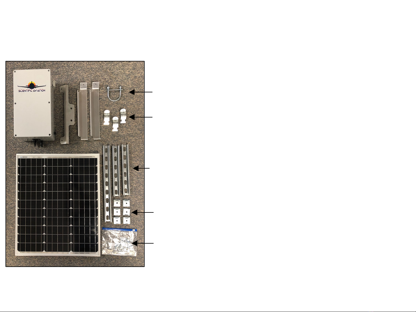
2a. Attach the solar panel to its mounting frame.
1) Measure & mark the pole at 6.0”, 13.5”, and 29.5” from the top.
2) Position the solar panel upper mounting bracket with the bend
facing the solar panel and attach with two ¼-20 x 5/8” hex head
bolts, lock washers, and nuts. Tighten nuts to 75 in-lbs.
3) Attach two solar panel lower mounting brackets to the other
edge of the solar panel with two ¼-20 x 5/8” hex head bolts,
lock washers, and nuts. Tighten nuts to 75 in-lbs.
4) Attach the other ends of the lower mounting brackets to the
14” long Unistrut channel with two ¼ -20 x 1.75” hex head
bolts, square Unistrut washers, lock washers, and nuts. Tighten
nuts to 75 in-lbs. Support the Unistrut channel and lower
mounting brackets to avoid bending the solar panel frame.
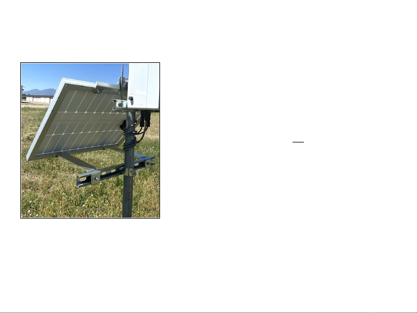
5) Place the solar panel and frame assembly at the base of the
pole and facing South.
(Continued on next page)

2b. Attach the solar panel to the pole.
6) Position the U-bolt around the pole, through the solar panel
upper mounting bracket, and through the rectangular U-bolt
mounting bracket. Install two 3/8” lock washers and nuts,
and leave loose.
7) Attach a Unistrut clamp to the Unistrut channel at the base
of the pole, install the pole clamp bolt and nut, and leave
loose.
8) Slide the solar panel assembly up the pole to position the U-
bolt at the 13.5” mark and the top of the Unistrut clamp at
the 29.5” mark below the top of the pole. Support the
Unistrut channel to avoid bending the solar panel frame.
9) Ensure the panel is facing South; tighten the Unistrut clamp
(75 in-lbs) and the U-bolt nuts (120 in-lbs) to secure the solar
panel to the pole.

3. Attach the SOOFIE enclosure to the pole.
1) Attach two 7.8”-long Unistrut channels to back of the SOOFIE
enclosure with four 10-32 x 2” pan head Phillips screws, #10
lock washers, #10 flat washers, and square Unistrut washers.
Torque to 16 in-lbs (1.8 Nm).
2) Position the top of a Unistrut clamp at the 6.0” mark below
the top of the pole and engage the upper Unistrut channel
on the SOOFIE enclosure. Slide the enclosure to the side
closest to the solar panel junction box.
3) Position another Unistrut clamp around the pole and engage
the lower Unistrut channel on the SOOFIE enclosure.
4) Tighten both Unistrut clamps securely (75 in-lbs).
Needs new pics

4. Power up the system and connect the cables.
1) Insert a 10A medium-blow fuse into a fuse receptacle cap;
push in FIRMLY and turn clockwise to install in the left-hand
fuse receptacle. Confirm fuse cap is locked and confirm
audible fan operation. This fuse completes the battery circuit;
SOOFIE is now operating!
2) Insert the (+) and (–) connectors from the solar panel into
the MC4 receptacles on the SOOFIE enclosure. Confirm both
connectors are fully inserted and locked.
3) Insert a 10A medium-blow fuse into a fuse receptacle cap;
push in FIRMLY and turn clockwise to install in the right-hand
fuse receptacle. Confirm fuse cap is engaged and locked.
This fuse completes the solar panel charging circuit.
4) (if applicable) Insert the anemometer cable connector into
the M8 receptacle on the SOOFIE enclosure and rotate the
knurled barrel on the cable connector until finger-tight.
Needs new pics

Troubleshooting

1. Open the SOOFIE enclosure.
1) Loosen all 6 recessed cover screws and remove cover.
NOTE:
Cover screws are not captive; do not flip the cover over.
CAUTION:
High-current DC voltage up to 25v is exposed with cover off.

2. Check fusing and wiring.
NOTE:
The two fuses are interchangeable, but their removal/reinsertion
order is important. The solar panel fuse MUST be removed first
AND reinserted last, following the sequence below.
1) Remove the solar panel fuse from right-hand fuse holder by
pushing in firmly and turning counter-clockwise ½ turn;
ensure fuse is intact or replace with a new 10A 250V
medium-blow 1/4" x 1-1/4” glass cartridge fuse.
2) Remove the battery fuse from left-hand fuse holder by
pushing in firmly and turning counter-clockwise ½ turn;
ensure fuse is intact or replace with a new 10A 250V
medium-blow 1/4" x 1-1/4” glass cartridge fuse.
3) Reinsert the battery fuse into left-hand fuse holder.
4) Reinsert the solar panel fuse into right-hand fuse holder.
5) Confirm that all cables are firmly captured in MPPT solar
controller screw terminals.
6) Confirm that crimp terminals are fully engaged on battery
and fuse holder tabs.
7) Confirm that the MTA connectors on the sensor board are
properly seated.

3. Check and record voltages.
With a voltmeter, check and record DC voltages between:
1) Terminals on LiFePO4battery: vDC
2) BATT terminals on MPPT charge controller: vDC
3) PV terminals on MPPT charge controller: vDC
Note: PV terminal voltage will be zero unless the
solar panel is connected and exposed to the sun
4) LOAD terminals on MPPT charge controller: vDC

4. Check operation
1) Check that the intake fan is running.
2) Check the two LEDs on the MPPT solar charge controller:
a. Green LED on or blinking? (power from battery)
b. Yellow LED on or blinking? (charging from panel)
3) Check the status LED on the Particle Boron/Argon
microprocessor:
a. pulsing cyan? (connected to Internet)
b. blinking green? (looking for cellular/wifi service)
c. magenta? (firmware update in progress)
If these steps haven’t identified an obvious problem with an immediate solution,
please call Scientific Aviation technical support at (xxx) xxx-xxxx
Other manuals for SOOFIE
1
Table of contents
Popular Control Unit manuals by other brands

Door Entry Direct
Door Entry Direct DC260 installation guide

Watts
Watts Series 709 installation instructions

tams elektronik
tams elektronik 53-02015 manual

Camozzi
Camozzi CX06 Series Operation and maintenance instruction

DIDIESSE
DIDIESSE Electronic System instruction manual

Revox
Revox Re:source MMM 01 user manual