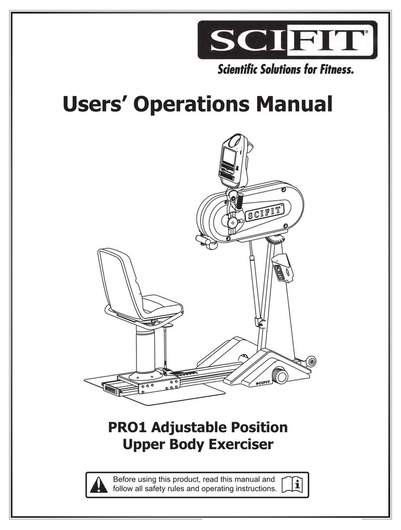
SCIFIT PRO1 Sport Instructions for use

Owner’s Operation Manual
Before Using this product, read this manual and
follow all safety rules and operating instructions.
PRO1 Adjustable Position
Upper Body Exerciser

SCIFIT • Scientic Solutions for Fitness • SCIFIT • Scientic Solutions for Fitness • SCIFIT
IMPORTANT!
The PRO1 machine has been delivered in
the “SHIPPING MODE”, which helps save
the internal 12V battery of this machine
It is important this mode be turned off.
Please do the following steps:
Turning off the “Shipping Mode”
(A) Begin to crank the machine.
(B) Press the [Quick Start] key and begin a workout.
(C) After 5 seconds press the [Pause/Clear] to pause the workout.
(D) Press the [Stop] key to exit the program.
(E) Stop cranking to let the machine power down.
The “Shipping Mode” has now been turned off.
WARNING! Heart rate monitoring systems may be inaccurate.
Over exercise may result in serious injury.
If you feel faint or pain stop exercising immediately
Quick
Start
Enter
Pause
Clear
Continue Change Stop
B
C
D

SCIFIT • Scientic Solutions for Fitness • SCIFIT • Scientic Solutions for Fitness • SCIFIT
TABLE OF CONTENTS
SAFETY INFORMATION
INTRODUCTION
SPECIFICATIONS
SET-UP & INSTALLATION
ASSEMBLY
PRODUCT OVERVIEW
KEYPAD FUNCTIONS
BIOMECHANICAL POSITIONING
ADJUSTMENTS
ACCESSORIES
HEART RATE TRANSMITTER STRAP
PROGRAM INSTRUCTIONS
MAINTENANCE & SERVICE
WARRANTY
CERTIFICATIONS
WARRANTY CARD
1
2
3-4
5
6-13
14-15
16
17
18-19
20-21
22
23-32
33
34-38
39
40
Order on line 24/7 at www.SCIFIT.com

SCIFIT • Scientic Solutions for Fitness • SCIFIT • Scientic Solutions for Fitness • SCIFIT
1
The purpose of safety symbols is to attract your
attention to possible dangers. The safety symbols
and their explanations deserve your careful attention
and understanding. The safety warnings do not, by
themselves eliminate any danger. The instructions
or warnings they give are not substitutes for proper
accident prevention measures.
Look for these symbols to point out important safety
precautions. It means attention! Your safety is involved.
Read all instructions before using your SCIFIT exercise
machine. Save these instructions for future reference.
Close supervision is necessary when the exercise
machine is being used by or near children and
individuals with disabilities. Keep children away from
extended hand and foot supports.
Use the exercise machine only for its intended use as
described in this manual. Do not use attachments not
recommended by the manufacturer.
Never drop or insert any object into any opening.
Do not use outdoors or in a harsh environment where
water is present (i.e. pool or spa areas).
WARNING
Failure to obey a safety warning can result in injury
to yourself and others. Always follow the safety
precautions to reduce the risk of personal injury.
CAUTION
Failure to obey a safety caution can result in injury
to yourself and others. Always follow the safety
precautions to reduce the risk of personal injury.
SAFETY INFORMATION

SCIFIT • Scientic Solutions for Fitness • SCIFIT • Scientic Solutions for Fitness • SCIFIT
2
Thank you for your purchase of the SCIFIT PRO1
adjustable position upper body exerciser. We have
incorporated the nest technology and ergonomic
design into this machine to assist you in achieving
your tness goals. However, for your safety, please
adhere to the following recommendations before you
begin to exercise.
The SCIFIT PRO1 upper body exerciser is designed for
Class “S” (Commercial), Class “A” (High Accuracy) and
Class “II a” (Medical Device Directive) applications.
The intended uses are for Cardio & Pulmonary
Rehabilitation as well as Sports Medicine, Physical
Therapy, Physical Conditioning and Strength Training.
SCIFIT equipment is suitable for placement in tness,
medical rehab, sports performance and recreational
facilities. The PRO1 has 200 levels of computer
controlled resistance, which ensures that users of all
tness levels will be able to get a challenging but not
overwhelming workout.
Consult Your Physician
Consult your physician or medical specialist before
participating in any exercise program, especially if
you are pregnant, or if you are suffering from: heart
disease, respiratory disease, diabetes, hypertension,
high blood pressure, elevated cholesterol, arthritis, or
any other diseases and physical complaints.
Adult Usage
SCIFIT equipment is designed and intended for adult
usage and children of appropriate ages while being
supervised. Young children should be kept a safe
distance away from equipment.
Cool Down
To prevent muscle injuries and soreness, you should
always cool down (at least 5 minutes) by doing a
series of stretches after each workout.
CAUTION
Always stretch after a workout session to reduce
the risk of personal injury. Failure to stretch properly
may result in injury to yourself.
Guidelines for Healthy Adults
The American College of Sports Medicine (ACSM) and
the American Heart Association (AHA) are continuously
updating guidelines and recommendations for physical
activity.
The current basic recommendations from ACSM and
AHA is:
Do moderately intense cardio 30 minutes a day, ve
days a week.
OR
Do vigorously intense cardio 20 minutes a day, three
days a week.
AND
Do eight to ten strength-training exercises, eight to
twelve repetitions of each exercise twice a week.
Moderate-intensity physical activity means working
hard enough to raise your heart rate and break a
sweat, yet still being able to carry on a conversation.
It should be noted that to lose weight or maintain
weight loss, 60 to 90 minutes of physical activity may
be necessary. The 30 minute recommendation is for
the average healthy adult to maintain health and
reduce the risk for chronic disease.
To review the latest guidelines and recommendations,
visit the American College of Sports Medicine website:
www.acsm.org
Train Intelligently
To ensure a future of good health, you should always
eat well balanced meals, drink plenty of uid/water
during a workout, and stay t by exercising intelligently.
Always follow training guidelines that are specic for
your own physical condition.
WARNING
Stop exercising immediately if you feel nausea,
dizziness, sharp pain, or any other physical
discomfort. Failure to stop exercising can result in
injury or death to yourself.
WARNING
Injuries to health may result from incorrect or
excessive training. Failure to stop exercising can
result in injury or death to yourself.
INTRODUCTION

SCIFIT • Scientic Solutions for Fitness • SCIFIT • Scientic Solutions for Fitness • SCIFIT
3
PRO1 - 248 lbs. (112 Kg.)
500 lbs. (227 Kg.) - Fixed Seat
450 lbs. (204 Kg.) - Swivel Seat
600 lbs. (272 Kg.) - Bariatric Seat
Self generating w/auto recharge battery back-up.
Standard low voltage AC adapter wall pack.
Electromagnetic Self Generating Bi-directional Resistance
Manual, Fit Quik, Constant Workout, ISO-Strength, 7 Pre-programmed Hills proles
Heart Rate, Power Fit, Heart Fit , Stress Test and Random
Class A
Within U.S. & Canada 3 years parts, 1 year labor
Outside U.S. 3 years parts, no labor
Weight
Max User Weight
Power
Resistance System
Programs
Accuracy Class
Warranty
SPECIFICATION
60”
1524 mm
30”
(762 mm)
67”
1702 mm

SCIFIT • Scientic Solutions for Fitness • SCIFIT • Scientic Solutions for Fitness • SCIFIT
4
PRO1 SPORT - 178 lbs. (81 Kg.)
Self generating w/auto recharge battery back-up.
Standard low voltage AC adapter wall pack.
Electromagnetic Self Generating Bi-directional Resistance
Manual, Fit Quik, Constant Workout, ISO-Strength, 7 Pre-programmed Hills proles
Heart Rate, Power Fit, Heart Fit , Stress Test and Random
Class A
Within U.S. & Canada 3 years parts, 1 year labor
Outside U.S. 3 years parts, no labor
Weight
Power
Resistance System
Programs
Accuracy Class
Warranty
SPECIFICATION
60”
1524 mm
30”
(762 mm)
74”
1880 mm

SCIFIT • Scientic Solutions for Fitness • SCIFIT • Scientic Solutions for Fitness • SCIFIT
5
SET-UP & INSTALLATION
Placement of Cardiovascular Machine
To aid in the placement of equipment, two wheels are
located on the front of the unit. Movement of machine
should be done with two people. Carefully lift the rear
of unit until wheels are engaged on oor and position
unit in desired location.
Position the unit in a location that has a stable and
level sub-oor. Equipment should be positioned in
a location that is not in direct sunlight, in areas of
extreme temperature and humidity, or where the
equipment may be splashed with water or uids. This
machine is intended for indoor use only.
Equipment should be positioned with a safety
perimeter of 40” or 1 meter around unit.
Level Cardiovascular Machine
If the sub-oor is unlevel, the unit is equipped with
leveling end caps. The end caps are designed with
the recess of end cap off centered. This allows you to
rotate the endcap(s) to a position that will level the
equipment. After adjustment, check and make sure
end caps are fully seated against base frame tubes.
WARNING
Failure to place the equipment on a stable and level
sub-oor with a safety perimeter can result in injury
to yourself and others.
Proper Supervision
Close supervision is required when the exercise
machine is being used by or near individuals with
disabilities. Keep unsupervised children outside the
safety perimeter.
Cleaning
Never clean the machine with organic solvents,
alcohol or bleach based cleaners. To promote a
healthy environment, wipe any sweat off of unit with
a commercially manufactured wipe designed for the
tness industry, or a damp cloth.
40” / 1 Meter
Safety Space
EndcapEndcap
40” / 1 Meter
Safety Space
40” / 1 Meter
Safety Space
40” / 1 Meter
Safety Space
Offset Endcap

SCIFIT • Scientic Solutions for Fitness • SCIFIT • Scientic Solutions for Fitness • SCIFIT
6
ASSEMBLY
2
(A )
(B)
(C)
(D )
34
Assemble Monocoque Frame to Base Frame
With the aid of a second person, align bottom mounting
threaded nut sets of Monocoque Frame with the Base
Frame mounting holes.
To aid in maintaining alignment, (A) insert a long
needle point center punch through one of the front
threaded mounting holes of the base frame. (B)
push up on frame until nut sets are aligned the with
mounting holes. (C) Slide (Qty.1) 3/8” split washer
and (Qty.1) 3/8” at washer onto each 3/8” bolt, then
align and loosely thread them into the three open
mounting holes. (D) Return to center punch and pull
it out to loosely thread in the last remaining bolt.
(E) Tighten all bolts to 576 in/lbs (65 n/m).
CAUTION
Monocoque Frame is top heavy. Two people are
required to position frame in place. Failure to support
frame properly may result in injury to yourself and/
or others.
Required Tools:
1/2” (13mm)Socket with Ratchet
Long Needle Point Center Punch
5/16” (8mm) Hex Bit
Required Parts:
Item Qty. Description Part No:
1 2 PRO Wheelchair Platform A2502
2 4 3/8 x 1” Socket HD Cap Bolt N/A
3 4 3/8 Flat Split Lock Washer N/A
4 4 3/8 Flat Washer N/A
Assembly
Some equipment shipped overseas assembly is
required. Follow the steps below for assembly.
Mount wheelchair Platforms to Base Frame
Locate two Wheelchair Platforms (A2502) and with
the aid of an assistant stand Base Frame on its
non wheeled end. (A) With a 1/2” socket, loosen
the four middle bolts that secure the Stainless
Steel Adjustment Track to base frame, just enough
to slide the platform under the lockwasher.
NOTE: Do Not remove or loosen bolts more than
necessary. (B) Engage slots of wheelchair platform
over the four bolts, between the lockwasher and
square tube. With the at horizontal surface of the
wheelchair platform ush against base frame square
tube, (C) tighten the four bolts. Repeat process for
the opposite side.
1
(A) Loosen
Four (4) Bolts
(B) Slide Slots
Under Washers
(C) Tighten Bolts

SCIFIT • Scientic Solutions for Fitness • SCIFIT • Scientic Solutions for Fitness • SCIFIT
7
Step 1:
Pull upward on the yellow T-handle of the seat adjustment lever, then lift and slide the seat post onto the frame
track making sure the roller guide rail is between the top and bottom wheels of the base.
Step 2:
Attach the handlebar plate to the seat post with (Qty. 4) of items #1, #2,
#3 and #4 as shown on the drawing below.
Roller guide
#1
#2
#3
#4
Tools Required:
3/16” (5mm) Hex Bit
1/2” (13mm) Wrench or socket
Item #1 (x4)
5/16-18 x 1 Socket Flat Head Screw
Item #2 (x4)
5/16 Flat Washer
Item #3 (x4)
5/16 Split Washer
Item #4 (x4)
5/16 Flat Nut
ASSEMBLY
SWIVEL SEAT ASSEMBLY

SCIFIT • Scientic Solutions for Fitness • SCIFIT • Scientic Solutions for Fitness • SCIFIT
8
ASSEMBLY
SWIVEL SEAT ASSEMBLY CONT’D
Step 3: (Bucket Seat Assembly )
a. Align the front holes of the bucket seat with the 3rd set of holes from the front of the handlebar plate,
(see diagram), then loosely screw in (Qty. 1) of item #1 into one of the front holes.
b. Align the other three holes and loosely screw in item #1 into each hole.
c. Tighten all four screws to secure the bucket seat.
Step 3a: (2-Piece Seat Assembly)
a. Align the front two holes of the seat mount plate with the 1st set of holes of the handlebar plate (see
diagram), then insert (Qty. 1) of item #1 into one of the front holes to hold the seat mount plate in place.
b. Align the front hole of the bottom seat pad with the inserted screw and loosely screw it into the seat pad.
c. Align the other front hole of the seat pad and loosely screw in (Qty. 1) of item #1 screw.
d. Slide (Qty. 1) of item #3, then (Qty. 2) of item #4 onto each item #2 screws, then loosely screw them into
the rear two holes of the seat pad.
E. Tighten all four screws to secure the bottom seat pad and plate mount
Tools Required:
1/2” (13mm) Wrench or socket
Tools Required:
1/2” (13mm) Wrench or socket
Item #1(x4)
5/16-18 x 1.25 Serrated Screw
#1
Item #1 (x2)
5/16-18 x 1.25 Serrated Screw
Item #2 (x2)
5/16-18 x 1 Hex Head Screw
Item #3 (x2)
5/16 Split Washer
Item #4 (x4)
5/16 Flat Washer
SCIFIT
#1 #2
#3
#4
Bottom Seat Pad
Seat Mount Plate
Rear holes of the bucket seat
Front holes of the bucket seat
Front seat plate mounting holes
Rear seat plate mounting holes

SCIFIT • Scientic Solutions for Fitness • SCIFIT • Scientic Solutions for Fitness • SCIFIT
9
FIXED SEAT ASSEMBLY
Step 1:
Pull upward on the yellow knob of the seat adjustment lever, then lift and slide the seat post onto the frame
track making sure the roller guide rail is between the top and bottom wheels of the base.
Step 2: (Bucket Seat Assembly)
a. Align the front two holes of the bucket seat and handlebar plate with the front set of holes on the xed seat
mount (see diagram), then insert (Qty. 1) of item #1 into one of the seat holes and loosely tighten into place.
b. Align the second front hole of the seat and loosely tighten with (Qty. 1) item #1 screw.
d. Insert and loosely tighten the remaining two rear holes with (Qty. 2) item #1 screws.
e. Tighten all four screws to secure the seat to the xed seat mount.
Roller guide
Align holes of seat with these
holes on the xed seat mount
Tools Required:
1/2” (13mm) Wrench or socket
Item #1 (x4)
5/16-18 x 1.25 Serrated Screw
Front
Rear
ASSEMBLY

SCIFIT • Scientic Solutions for Fitness • SCIFIT • Scientic Solutions for Fitness • SCIFIT
10
FIXED SEAT ASSEMBLY CONT’D
Step 2a: (2-Piece Seat Assembly)
a. Align the front two holes of the seat mount plate with the 1st set of holes of the xed seat mount. (see
diagram), then insert (Qty. 1) of item #1 into one of the front holes to hold the seat mount plate in place.
b. Align the front hole of the bottom seat pad with the inserted screw and loosely screw it into the seat pad.
c. Align the other front hole of the seat pad and loosely screw in (Qty. 1) of item #1 screw.
d. Align, then loosely screw in (Qty. 2) of item #1 into the two remaining rear holes.
e. Tighten all four screws to secure the bottom seat pad and plate mount.
(Item #1) x 4
Tools Required:
1/2” (13mm) Wrench or socket
Item #1 (x 2)
5/16-18 x 1.25 Serrated Screw
Align bottom seat pad holes
with these four hole locations
ASSEMBLY

SCIFIT • Scientic Solutions for Fitness • SCIFIT • Scientic Solutions for Fitness • SCIFIT
11
Verify Upper Cranks Are Secure
During shipment it is possible that the two set screws securing the crank hub to the shaft may become slightly loose.
It is strongly recommended that these set screws be checked before attaching the crank handles.
The following steps will explain this procedure.
Tools Required
• 5/16” (8mm) Hex bit
• Torque wrench set for 480 in/lbs (54 n/m).
Step 1:
Starting on the right side, use a 5/16 Hex bit to remove the
1st set screw #P3110 (5/8-18 x .5 Socket) and place to the
side.
Step 2:
Using a 5/16 Hex bit and Torque wrench set at 480 in/lbs.
Insert the bit into the crank hub to reach the 2nd set screw
#P3111 (5/8-18 x .75 Socket) and TIGHTEN to the 480 in/lb
setting on the wrench.
Note: The wrench will click when it has reached the
480 in/lb (54 n/m) setting.
Step 3:
Again using a 5/16 Hex bit and Torque wrench set at
480 in/lbs, reinsert the set screw removed in step 1 into
the crank hub and TIGHTEN to the 480 in/lb setting on
the wrench.
Step 4:
Repeat steps 1 thru 3 for the left side.
ASSEMBLY

SCIFIT • Scientic Solutions for Fitness • SCIFIT • Scientic Solutions for Fitness • SCIFIT
12
ASSEMBLY
Assemble Hand Crank Handles to Hubs
Identify Left and Right Hand Crank Handles
(A) Insert parallel rods through bearing holes of hub.
(B) Pull yellow crank arm locking pin out and push
rods through until end of rod protrudes from far side.
Release pin and move arm until it locks into position.
(C) To prevent unwanted dropping of crank arm when
adjusting crank arm positions, install a 1/4-20 x 1/2”
socket button head screw and 1/4” washer into the
end of each rod.
Left Hand
Crank Handle Right Hand
Crank Handle
Wheelchair Platform
For equipment that is shipped assembled, the
wheelchair platforms need to be installed.
With the aid of an assistant, carefully raise the base
up, and lower the work console down until the console
is resting on the oor. To prevent damage to the case,
place a pad, piece of carpet or cardboard between the
case and oor.
(A) With a 1/2” (13mm) socket, loosen the four top
bolts that secure the stainless steel adjustment track
to the base frame, just enough to slide the platform
under the lockwasher. NOTE: Do Not remove or
loosen bolts more than necessary.
(B) Engage the slots of the wheelchair platform over
the four bolts, between the lockwasher and square
tube. With the at horizontal surface of the wheelchair
platform ush against the base frame square tube.
(C) Tighten the four bolts. Repeat the process for the
opposite side
Left Hand Crank
Handle Shown
1/4-20 x 1/2”
SBH Screw
1/4”
Washer
(A) Loosen
Four (4) Bolts
(B) Slide Slots
Under Washers
(C) Tighten Bolts
Protective Pad
(C)
(A)
(B)

SCIFIT • Scientic Solutions for Fitness • SCIFIT • Scientic Solutions for Fitness • SCIFIT
13
ASSEMBLY
FRAME
CROSSBAR
MOLDED
CUT-OUT
HOOK
OVERLAP
SCIFIT
DECAL
SCIFIT
DECAL
PRO1 Sport Platform Attachment
The PRO1 Sport will come with two symetrical molded
platforms, that can be easily attached to the frame of
the machine.
Step 1:
Take the rst platform and position it over the machine
frame with the SCIFIT decal pointing forward.
Place the platform onto the square tubing and
crossbar, verifying a proper t.
Align the formed cut-out running along the underside
of the platform with the frame’s square tubing.
Step 2:
Align the molded hook overlap at the front of the
platform with the small crossbar attached between
the frame’s two square tubing.
Step 3:
Step 4:
Step 5:
Take the second platform and postion it over the
machine frame with the SCIFIT decal pointing toward
the rear.
Step 6:
Repeat steps 2 thru 4.

SCIFIT • Scientic Solutions for Fitness • SCIFIT • Scientic Solutions for Fitness • SCIFIT
14
PRODUCT OVERVIEW
Adjustable display
& Intelli-Fit console
Adjustable crank arm
(Right side reversible)
Water Bottle
Holder
Transport wheels
Leveling base
endcaps
Molded footrest
Wheelchair
platform
Fixed or
adjustable swivel seat.
(Swivel shown)
Adjustment
lever
PRO1

SCIFIT • Scientic Solutions for Fitness • SCIFIT • Scientic Solutions for Fitness • SCIFIT
15
PRODUCT OVERVIEW
Adjustable display
& Intelli-Fit console
Adjustable crank arm
(Right side reversible)
Water Bottle
Holder
Transport wheels
Leveling
endcaps
Preformed
Platform
Adjustment
lever
PRO1 SPORT

SCIFIT • Scientic Solutions for Fitness • SCIFIT • Scientic Solutions for Fitness • SCIFIT
16
KEYPAD FUNCTIONS
SCIFIT • Scientific Solutions for Fitness • SCIFIT • Scientific Solutions for Fitness • SCIFIT
WARNING! Heart rate monitoring systems may be inaccurate.
Over exercise may result in serious injury.
If you feel faint or pain stop exercising immediately
Quick
Start
Enter
Pause
Clear
Manual Fit-Quik Constant Hills
Iso-Strength More
Work Level Status Screen:
The LCD screen gives the user a
progressive real-time view of the
current workout categories for
the program selected.
Pause/Clear:
The [Pause/Clear] key will
pause a workout at anytime,
then provide three options
(see Program Instructions)
Enter:
The [Enter] key
is used to verify
selected values for
workout parameters.
Quick Start:
This key provides a one-touch
“Quick Start” into a workout
with preset parameters.
“Quick Start” also begins a
program after all information
has been entered.
Up and Down Arrows:
These keys increase or
decrease values of the
workout parameters.
Prole
Selection Area:
Allows the user up to
10 different workout
proles to chose.

SCIFIT • Scientic Solutions for Fitness • SCIFIT • Scientic Solutions for Fitness • SCIFIT
17
PRO1 Sport
Spread both feet and place them securely on the
platform and in a comfortable position. Do not lock
the knees and do not allow the feet to move beyond
the platform. The PRO1 Sport encourages function
and natural movement, therefore ideal foot placement
and body position depends on the goal of the user.
Adjust the height and angle of the cranks and to a
comfortable position that encourages proper posture
for specic training movements (see page 18).
PRO1 With Seat Assemblies
Adjust the seat or wheelchair forward or backward to
a comfortable location for the upper body movement.
A slight torso rotation is desired on extension. Avoid
locking arms at extension by adjusting the seat position
or arm crank length. Adjust the height and angle of
the cranks to a comfortable position that encourages
proper posture for specic training or rehabilitation
movements. Such movements and adjustments
should be under the guidance and supervision of a
tness or medical professional. If your PRO1 features
a seat with height adjustment, you may adjust either
the seat height or the main body to obtain the desired
axis of rotation and body position.
Crank Arm Radius
Adjust the crank arm radius by changing the crank
position length. The longer the crank arm length
the larger the circle the user will experience when
exercising. Generally a larger circle will result in
broader muscle recruitment and greater torso rotation.
Comfort is a key issue and these guidelines may be
helpful.
Users Height:
5’ 6” and under = shortest crank settings
5’ 7” to 5’10” = middle two crank settings
5’ 11” and taller = longest crank setting
Important Note: When using this product for medical
or rehabilitation purpose, the crank radius, seat height
and distance should be set by the attending therapist
or medical professional based on the specic needs of
the user.
CAUTION
Always follow medical professionals guidelines to
reduce the risk of personal injury. Failure to follow
their directions may result in injury to yourself.
BIOMECHANICAL POSITIONING
9” Radius
1st hole position
8” Radius
2nd hole position
7” Radius
3rd hole position
6” Radius
4th hole position
Other manuals for PRO1 Sport
5
Table of contents
Other SCIFIT Home Gym manuals
Popular Home Gym manuals by other brands
CORFLEX
CORFLEX Marathon Air Walker Ankle Application Instructions
Impex
Impex Marcy SB-685 owner's manual
Weider
Weider 195 Tc Bench Manuel de l'utilisateur
Weider
Weider 170 Tc Bench Manuel de l'utilisateur
ParaBody
ParaBody 841101 Assembly instructions

Weider
Weider Gold MEDALLION M4744 Assembly instructions
