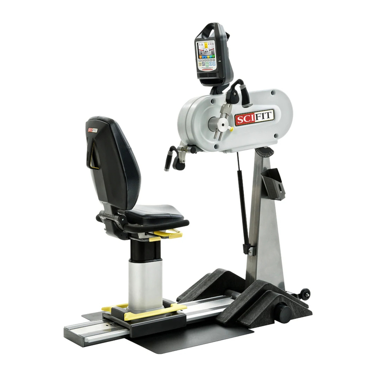
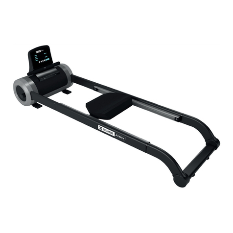
SCIFIT PRO1 Sport Mounting instructions

Users’ Operations Manual
Before using this product, read this manual and
follow all safety rules and operating instructions.
PRO1 Adjustable Position
Upper Body Exerciser

SCIFIT • Scientific Solutions for Fitness • SCIFIT • Scientific Solutions for Fitness • SCIFIT
This page purposely left blank

TABLE OF CONTENTS
SAFETY INFORMATION. . . . . . . . . . . . . . . . . . . . . . . . . . . . . . . . . . . . . . . . 1
INTRODUCTION . . . . . . . . . . . . . . . . . . . . . . . . . . . . . . . . . . . . . . . . . . . . . .2
SPECIFICATIONS . . . . . . . . . . . . . . . . . . . . . . . . . . . . . . . . . . . . . . . . . . . . .3
SETUP & INSTALLATION . . . . . . . . . . . . . . . . . . . . . . . . . . . . . . . . . . . . . . 4
ASSEMBLY . . . . . . . . . . . . . . . . . . . . . . . . . . . . . . . . . . . . . . . . . . . . . . . . . 5 - 11
PRODUCT OVERVIEW . . . . . . . . . . . . . . . . . . . . . . . . . . . . . . . . . . . . . . . . 12
KEYPAD FUNCTIONS . . . . . . . . . . . . . . . . . . . . . . . . . . . . . . . . . . . . . . . . . 13
BIOMECHANICAL POSITIONING . . . . . . . . . . . . . . . . . . . . . . . . . . . . . . . . 14
ADJUSTMENTS . . . . . . . . . . . . . . . . . . . . . . . . . . . . . . . . . . . . . . . . . . . . . . 15 - 16
ACCESSORIES . . . . . . . . . . . . . . . . . . . . . . . . . . . . . . . . . . . . . . . . . . . . . . .17
HEART RATE TRANSMITTER STRAP . . . . . . . . . . . . . . . . . . . . . . . . . . . . .18
PROGRAM INSTRUCTIONS . . . . . . . . . . . . . . . . . . . . . . . . . . . . . . . . . . . . 19 - 27
MAINTENANCE & SERVICE . . . . . . . . . . . . . . . . . . . . . . . . . . . . . . . . . . . . 28
WARRANTY. . . . . . . . . . . . . . . . . . . . . . . . . . . . . . . . . . . . . . . . . . . . . . . . . . 29 33-
SCIFIT • Scientific Solutions for Fitness • SCIFIT • Scientific Solutions for Fitness • SCIFIT
Orderonline 24/7 atwww.SCIFIT.com

SCIFIT •
S
cientific
Solutions for Fi
tness • SCIFIT •
S
cientific
Solutions for Fi
tness •
SCIFIT
SAFETY INFORMATION
1
Read all instructions before using your SCIFIT
exercise machine. Save these instructions for future
reference.
Closesupervision is necessary whenexercisemachine
is being used by, or near children, or individuals with
disabilities. Keep children away from extended hand
and foot supports.
Use the exercise machine only for its intended use as
described in this manual. Do not use attachments not
recommended by the manufacturer.
Never drop or insert any object into any opening.
Do not use outdoors or in a harsh environment where
water is present (i.e. pool or spa areas).
Failure to obey a safety warning
can
result in injury
to yourself and others. Always follow the safety
precautions to reduce the risk of personal injury.
The purpose of safety symbols is to attract your
attention to possible dangers. The safety symbols,
and their explanations, deserve your careful attention
and understanding.The safety warnings do not, by
themselves, eliminate any danger.The instructions
or warnings they give are not substitutes for proper
accident prevention measures.
Look for these symbols to point out important safety
precautions. It means attention! Your safety is
involved.
WARNING
Failure to obey a safety caution
can
result in injury
to yourself and others. Always follow the safety
precautions to reduce the risk of personal injury.
CAUTION

SCIFIT • Scientific Solutions for Fitness • SCIFIT • Scientific Solutions for Fitness • SCIFIT
INTRODUCTION
2
Thank you for your purchase of the SCIFIT
PRO1 Adjustable Position Upper Body Exerciser. We
have incorporated the finest technology and ergonomic
design into this machine to assist you in achieving
your fitness goals. However, for your safety, please
adhere to the following recommendations before you
begin to exercise.
The SCIFIT PRO1 Upper Body Exerciser is designed
for Class “S” (Studio), Class “I” (Special Needs) and
Class “II a” (Medical Device Directive) applications.
The intended uses are for Cardio & Pulmonary
Rehabilitation as well as Sports Medicine, Physical
Therapy, Physical Conditioning and Strength Training.
SCIFIT equipment is suitable for placement in fitness,
medical rehab, sports performance and recreational
facilities. The PRO1 has 200 levels of computer
controlled resistance, which ensures that users of all
fitness levels will be able to get a challenging but not
overwhelming workout.
Consult Your Physician
Consult your physician or medical specialist before
participating in any exercise program, especially if
you are pregnant, or if you are suffering from: heart
disease, respiratory disease, diabetes, hypertension,
high blood pressure, elevated cholesterol, arthritis, or
any other diseases or physical complaints.
Adult Usage
SCIFIT equipment is designed and intended for adult
usage and children of appropriate ages while being
supervised. Young children should be kept a safe
distance away from equipment.
Cool Down
To prevent muscle injuries and soreness, you should
always cool down (at least 5 minutes) by doing a
series of stretches after each workout.
Train Intelligently
To ensure a future of good health, you should always
eat well balanced meals, drink plenty of fluid/water
during a workout, and stay fit by exercising intelligently.
Always follow training guidelines that are specific to
your own physical condition.
Stop exercising immediately if you feel nausea,
dizziness, sharp pain, or any other physical
discomfort. Failure to stop excercising can result in
injury or death to yourself.
WARNING
Always stretch after a workout session to reduce
the risk of personal injury. Failure to stretch
properly may result in injury to youerself.
CAUTION
Guidelines for Healthy Adults
The American College of Sports Medicine (ACSM) and
the American Heart Association (AHA) are continuously
updating guidelines and recommendations for physical
activity.
The current basic recommendations from ACSM and
AHA is:
Do moderately intense cardio 30 minutes a day, five
days a week.
OR
Do vigorously intense cardio 20 minutes a day, three
days a week.
AND
Do eight to ten strength-training exercises, eight to
twelve repetitions of each exercise twice a week.
Moderate-intensity physical activity means working
hard enough to raise your heart rate and break a
sweat, yet still being able to carry on a conversation.
It should be noted that to lose weight or maintain
weight loss, 60 to 90 minutes of physical activity may
be necessary. The 30 minute recommendation is
for the average healthy adult to maintain health and
reduce the risk for chronic disease.
To review the latest guidelines and recommendations,
visit the American College of Sports Medicine website:
www.acsm.org
Injuries to health may result from incorrect or
excessive training. Failure to stop excercising can
result in injury or death to yourself.
WARNING

SCIFIT • Scientific Solutions for Fitness • SCIFIT • Scientific Solutions for Fitness • SCI FI T
SPECI FI CATI ONS
3
Weight . . . . . . . . . PRO1-248 lbs.(112 Kg.) / PRO1 SPORT - 178 lbs. (81 Kg.)
Max User Weight . . 500 lbs.(227 Kg.)- Fixed Seat
450 lbs.(204 Kg.)- Swivel Seat
Power . . . . . . . . . . Self generating w/auto recharge battery back-up.
Optional Low Voltage AC adapter available.
Resistance System . Electromagnetic Self Generating Bi-directional Resistance
Programs . . . . . . . Manual, Fit Quik, Constant Workout, ISO-Strength, 7 pre-programmed Hills profiles,
Heart Rate, Power Fit test, Power Fit traing, Heart Fit test, Heart Fit Training, Stress Test
and Random
Accuracy Class. . . . . Class A
Warranty . . . . . . . . Within U.S. & Canada 3 years parts, 1 year labor
Outside U.S. 3 years parts, no labor
30”
762 mm
60”
1524 mm
67”
1702 mm
600 lbs.(272 Kg.)- Bariatric Seat

SETUP & INSTALLATION
SCIFIT •
S
cientific
Solutions for Fi
tness • SCIFIT •
S
cientific
Solutions for Fi
tness •
SCIFIT
4
Placement of Cardio Machine
To aid in the placement of equipment, two wheels
are located on the front of the unit. Movement of
machine should be done with two people. Carefully
lift the rear of the unit until the wheels are engaged
.noitacolderisednitinunoitisopdnaroo
fl
no
Position the unit in a location that has a stable and
level
sub-floo
r. Equipment should be positioned
in a location that is not in direct sunlight, in areas
of extreme temperature and humidity, or where
the equipment may be splashed with water or
fluids.
This machine is intended for indoor use only.
Equipment should be positioned with a safety
perimeter of 40” or 1 meter around the unit.
Level Cardiovascular Machine
If the sub-floor is unle
vel, the unit is equipped with
leveling end caps. The end caps are designed with
the recess of end cap off centered. This allows you
to rotate the endcap(s) to a position that will level
the equipment. After adjustment, check and make
sure end caps are fully seated against base frame
tubes.
40” / 1 Meter
Safety Space 40” / 1 Meter
Safety Space
40” / 1 Meter
Safety Space
40” / 1 Meter
Safety Space
Offset Endcap
Endcap Endcap
Proper Supervision
Close supervision is required when the exercise
machine is being used by or near individuals with
disabilities. Keep unsupervised children outside the
safety perimeter.
Cleaning
Never clean the machine with orga ,stnevloscin
alcohol or bleach based cleaners. To promote a
healthy environment, wipe any sweat off of unit with
a commercially manufactured wipe designed for the
finess industr
y, or a damp cloth.
Failure to place the equipment on a stable and level
sub-floor with a safety perimeter can result in injury
to yourself and others.
WARNING

ASSEMBLY
SCIFIT •
S
cientific
Solutions for Fi
tness • SCIFIT •
S
cientific
Solutions for Fi
tness •
SCIFIT
5
Required Tools:
1/2” Socket with Ratchet
Long Needle Point Center Punch
5/16” Allen Drive Socket
Mount Wheelchair Platforms to Base Frame
Locate two Wheelchair Platforms (A2502) and with the aid
.dnedeleehwnonstinoemarFesaBdnats,tnatsissanafo
(A)
With a 1/2” socket, loosen the four middle bolts that
secure the Stainless Steel Adjustment Track to base frame,
.rehsawkcolehtrednumroftalpehtedilsothguonetsuj
NOTE: Do Not remove or loosen bolts more than
necessary. (B)
Engage slots of wheelchair platform over
the four bolts .ebuterauqsdnarehsawkcolehtneewteb,
With the
flat
horizontal surface of the wheelchair platform
flush
against base frame square tube,
(C)
tighten the four
bolts. Repeat process for the opposite side.
Required Parts:
1 2 PRO Wheelchair Platform A2502
2 4 3/8 x 1” Socket HD Cap Bolt N/A
3 4 3/8 Flat Split Lock Washer N/A
4 4 3/8 Flat Washer N/A
Assembly
Some equipment shipped overseas assembly is required.
Follow the steps below for assembly.
Monocoque Frame is top heavy. Two people are
required to position frame in place. Failure to support
frame properly
may
result in injury to yourself and/or
others.
CAUTION
Assemble Monocoque Frame to Base Frame
With the aid of a second person, align bottom mounting
threaded nutserts of Monocoque Frame with the Base
Frame mounting holes.
To aid in maintaining alignment,
(A)
insert a long needle
point center punch through one of the front threaded
mounting holes of the base frame.
(B)
push up on frame
until nut-serts are aligned the with mounting holes.
(C)
Slide
(Qty.1) 3/8” split washer and (Qty.1) 3/8” flat washer onto
each 3/8” bolt, then align and
loosely thread
them into the
three open mounting holes.
(D)
Return to center punch and
pull it out to loosely thread in the last remaining bolt.
(E)
Tighten all bolts to 48 ft/lbs or 576 in/lbs (6.64 kg/m).
1
(A)
Loosen
Four (4) Bolts
(B)
Slide Slots
Under Washers
(C)
Tighten Bolts
2
(A)
(B)
(C)
(D)
34
Item Qty. Description Part No:

ASSEMBLY
SCIFIT •
S
cientific
Solutions for Fi
tness • SCIFIT •
S
cientific
Solutions for Fi
tness •
SCIFIT
6
SWIVEL SEAT ASSEMBLY
Tools Required:
Step 1:
Pull upward the yellow paddle handle of the seat adjustment lever, then lift and slide the seat post onto
the frame track making sure the roller guide rail is between the top and bottom wheels of the base.
3/16 Hex wrench
1/2” Wrench or socket
Roller guide
Step 2:
Attach the handlebar plate to the seat post with (Qty. 4) of items #1, #2,
#3 and #4 as shown on the drawing below.
Item #1 (x 4)
5/16-18 x 1 Socket Flat Head Screw
Item #2 (x 4)
5/16 Flat Washer
Item #3 (x 4)
5/16 Split Washer
Item #4 (x 4)
5/16 Nut
#1
#2
#3
#4

ASSEMBLY
SCIFIT •
S
cientific
Solutions for Fi
tness • SCIFIT •
S
cientific
Solutions for Fi
tness •
7
SWIVEL SEAT ASSEMBLY CONT’D
Tools Required:
Step 3: (Bucket Seat Assembly )
a. Align the front holes of the bucket seat with the 3rd set of holes from the front of the handlebar plate,
(see diagram), then loosely screw in (Qty. 1) of item #1 into one of the front holes.
b. Align the other three holes and loosely screw in item #1 into each hole.
c. Tighten all four screws to secure the bucket seat.
1/2” Wrench or socket
Step 3a: (2-Piece Seat Assembly)
a. Align the front two holes of the seat mount plate with the 1st set of holes of the handlebar plate
(see diagram), then insert (Qty. 1) of item #1 into one of the front holes to hold the seat mount plate
in place.
b. Align the front hole of the bottom seat pad with the inserted screw and loosely screw it into the seat pad.
c. Align the other front hole of the seat pad and loosely screw in (Qty. 1) of item #1 screw.
d. Slide (Qty. 1) of item #3, then (Qty. 2) of item #4 onto each item #2 screws, then loosely screw
them into the rear two holes of the seat pad.
e. Tighten all four screws to secure the bottom seat pad and plate mount.
Item #1 (x 4)
5/16-18 x 1.25 Serrated Screw
#1
#1 #2
#3
#4
Item #1 (x 2)
5/16-18 x 1.25 Serrated Screw
Item #2 (x 2)
5/16-18 x 1 Hex Head Screw
Item #3 (x 2)
5/16 Split Washer
Item #4 (x 4)
5/16 Flat Washer
Tools Required:
1/2” Wrench or socket
Rear holes to mount Seat plate
Two front holes to mount Seat plate
Rear holes for Bucket seat
Front holes for Bucket seat
Seat Mount Plate
Bottom Seat Pad

ASSEMBLY
SCIFIT •
S
cientific
Solutions for Fi
tness • SCIFIT •
S
cientific
Solutions for Fi
tness •
SCIFIT
8
FIXED SEAT ASSEMBLY
Step 1:
Pull upward the yellow knob of the seat adjustment lever, then lift and slide the seat post onto
the frame track making sure the roller guide rail is between the top and bottom wheels of the base.
Roller Guides
Tools Required:
1/2” Wrench or socket
Item #1 (x 4)
5/16-18 x 1.25 Serrated Screw
Step 2: (Bucket Seat Assembly)
a. Align one of the front two holes of the Bucket seat with the front set of holes on the fixed seat mount
(see diagram), then insert (Qty. 1) of item #1 into one of the seat holes and loosely tighten into place.
b. Align the second front hole of the seat and loosely tighten with (Qty. 1) item #1 screw.
d. Insert and loosely tighten the remaining two rear holes with (Qty. 2) item #1 screws.
e. Tighten all four screws to secure the seat to the fixed seat mount.
Align holes of seat with these
holes on the fixed seat mount.
Front
Rear

ASSEMBLY
SCIFIT •
S
cientific
Solutions for Fi
tness • SCIFIT •
S
cientific
Solutions for Fi
tness •
SCIFIT
9
FIXED SEAT ASSEMBLY CONT’D
Align bottom seat pad holes
with these four hole locations
(Item #1) x 4
Step 2a: (2-Piece Seat Assembly)
a. Align the front two holes of the seat mount plate with the 1st set of holes of the fixed seat mount.
(see diagram), then insert (Qty. 1) of item #1 into one of the front holes to hold the seat mount plate
in place.
b. Align the front hole of the bottom seat pad with the inserted screw and loosely screw it into the seat pad.
c. Align the other front hole of the seat pad and loosely screw in (Qty. 1) of item #1 screw.
d. Align, then loosely screw in (Qty. 2) of item #1 into the two remaining rear holes.
e. Tighten all four screws to secure the bottom seat pad and plate mount.
Item #1 (x 2)
5/16-18 x 1.25 Serrated Screw
Tools Required:
1/2” Wrench or socket

ASSEMBLY
SCIFIT • Scientific Solutions for Fitness • SCIFIT • Scientific Solutions for Fitness • SCI FI T
10
Verifying Crank Hubs Secure
During shipment it is possible that the two set screws securing the crank hub to the shaft may become slightly loose.
It is strongly recommended that these set screws be checked before attaching the crank handles.
The following steps will explain this procedure.
Tools Required:
5/16 Hex bit
Torque wrench set for 480 in/lbs.
Step 1:
Starting on the right side, use a 5/16 Hex bit to remove the
1st set screw #P3110 (5/8-18 x .5 Socket) and place to the
side.
Step 2:
Using a 5/16 Hex bit and Torque wrench set at 480 in/lbs.
Insert the bit into the crank hub to reach the 2nd set screw
#P3111 (5/8-18 x .75 Socket) and TIGHTEN to the 480 in/lb
setting on the wrench.
Note: The wrench will click when it has reached the
480 in/ lb (5.53 Kg/m)setting.
Step 3:
Again using a 5/16 Hex bit and Torque wrench set at
480 in/lbs, reinsert the set screw removed in step 1 into the
crank hub and TIGHTEN to the 480 in/lb setting on the
wrench.
Step 4:
Repeat steps 1 thru 3 for the left side.

ASSEMBLY
SCIFIT •
S
cientific
Solutions for Fi
tness • SCIFIT •
S
cientific
Solutions for Fi
tness •
SCIFIT
11
Left Hand
Crank Handle Right Hand
Crank Handle
Assemble Hand Crank Handles to Hubs
Identify Left and Right Hand Crank Handles
(A)
Insert parallel rods through bearing holes of hub.
(B)
Pull yellow crank arm locking pin out and push
rods through until end of rod protrudes from farside.
.noitisopotniskcoltilitnumraevomdnanipesaeleR
(C)
To prevent unwanted dropping of crank arm when
adjusting crank arm positions, install a 1/4-20 x 1/2”
socket button head screw and 1/4” washer into the
end of each rod.
1/4”
Washer
Left Hand Crank
Handle Shown
(A)
1/4-20 x 1/2”
SBH Screw
(C)
(B)
Wheelchair Platform
For equipment that is shipped assembled, the
wheelchair platforms need to be installed.
With the aid of an assistant, carefully raise the base
up, and lower the work console down until the console
is resting on the
floo
r. To prevent damage to the case,
place a pad, piece of carpet or cardboard between the
case and
floo
r.
(A)
With a 1/2” socket, loosen the four top bolts that
secure the Stainless Steel Adjustment Track to the
base frame, just enough to slide the platform under the
lockwasher.
NOTE: Do Not remove or loosen
bolts more than necessary.
(B)
Engage
the four bolts, between the lockwashe and square tube.
With the flat
horizontal surface of the wheelchair
platform
flush against the base frame square tube.
(C)
Tighten the four bolts. Repeat the process for the Protective Pad
(A)
Loosen
Four (4) Bolts
(B)
Slide Slots
Under Washers
(C)
Tighten Bolts
the slots of the wheelchair platform over
opposite side.

PRODUCT OVERVIEW
SCIFIT •
S
cientific
Solutions for Fi
tness • SCIFIT •
S
cientific
Solutions for Fi
tness •
SCIFIT
12
Leveling Base
Endcaps
Water Bottle
Holder
Transport Wheels
Adjustable Display
& Control Console
Adjustable Crank Arm
(Right Side is Reversible)
Wheelchair Platform
Fixed or
Adjustable Swivel Seat.
(Swivel Shown)
Molded Footrest
Adjustment
Lever

KEYPAD FUNCTI ONS
SCIFIT • Scientific Solutions for Fitness • SCIFIT • Scientific Solutions for Fitness • SCI FI T
13
-
QUICK START-This key provides a one-touch
PAUSE/CLEAR - The [Pause/Clear]
key will pause the workout. Pressing
[Pause/Clear] a second time when in
the pause mode will stop the workout
and return to the main screen.
To restart in the paused mode press
the[Quick Start] key.
ENTER -
Work Level Status LCD Screen -
The Work Level Status LCD Screen gives
a progressive real-time indication of the
current work level of any and all programs
o
0
ll s g
o s o o a o ra
Profile Selection Area -
Allows the user option to
choose from 12 different
workout profiles
The Enter Key is pressed to
enter selected values for the
workout parameters.
“Quick Start” into the Manual mode, or after logging
into a program.The Quick Start key will activate the
selected program.
Up Arow and Down Arrow - These keys
increase or decrease values of the workout
parameters.

BIOMECHANICAL POSITIONING
SCIFIT •
S
cientific
Solutions for Fi
tness • SCIFIT •
S
cientific
Solutions for Fi
tness •
SCIFIT
14
Standing Use
.esabfokcabehtffognidilsyb1ORPehtmorftaesevomeR
Place feet securely in a comfortable position. Do not lock
.mroftalpehtdnoyebevomotteefwollatonoddnaseenk
The PRO1 encourages function and natural movement;
therefore, ideal foot placement and body position depends
on the goal of the user. Adjust the height of the cranks to
a comfortable position that encourages proper posture or at
the desired angle f
or specific t
raining movements.
Swivel or Fixed Seat and Wheelchair Use
Adjust seat or wheelchair forward or backward to a
comfortable location for the upper body movement. A slight
torso rotation is desired on extension. Avoid locking arms
at extension by adjusting the seat position or arm crank
radius. Adjust the height of the cranks to a comfortable
position that encourages proper posture or at the desired
angle for
specific
training or rehabilitation movements. Such
movements and adjustments should be under the guidance
and supervision of a
fitness
or medical professional. If
your Pro1 features a seat with height adjustment, you may
adjust either the seat height or the control head to obtain
the desired axis of rotation and body position
.
Crank Length Adjustment
Adjust crank arm radius to desired length. The longer the
crank arm length the larger the circle the user will experience
when exercising. Generally a larger circle will result in
broader muscle recruitment and greater torso rotation.
Comfort is a key issue and these guidelines may be
helpful.
Users Height:
5’ 6” and under = shortest crank settings
5’ 7” to 5’10” = middle two crank settings
5’ 11” and taller = longest crank setting
Important Note:
When using this product for medical
or rehabilitation purpose, the crank radius, seat height and
distance should be set by the attending therapist or medical
professional based on the speci
fi
c needs of the user.
Always follow medical professionals guidelines to
reduce the risk of personal injury. Failure to follow
their directions
may
result in injury to yourself.
CAUTION

ADJUSTMENTS
SCIFIT •
S
cientific
Solutions for Fi
tness • SCIFIT •
S
cientific
Solutions for Fi
tness •
SCIFIT
15
Crank Arm Adjustment
Crank arms can be adjusted to accomodate user height,
achieve proper bio-mechanical positioning and work
different muscle groups. To adjust crank arm position, pull
yellow spring loaded locking pin out and move crank arm to
new position.
Reversing Crank Arms
The upper body crank arms can be easily adjusted to work
in unison or in a rotary rowing motion. To take advantage of
this feature,
first
remove the Allen head screw and washer
from the steel crank rods on the right side of the unit. The
allen keys and instructions are included in your owners
package. This is done one time only. To reverse the crank,
pull the yellow pin and slide the crank arm completely out
of the Crank hub. Pull the yellow pin and re-insert the crank
arm carefully in the opposite position. The crank arms will
now be working in unison.
Using your SCIFIT PRO1 in this manner encourages
abdominal and back involvement and can be used to in the
tr
eatment of specific medical conditions.
Fixed Seat Adjustment
Seat position is dependent on user height, work console
position and crank arm adjustment. The seat should be
positioned so that the arm has a slight bend at the furthest
rotation point of crank arm. To adjust seat, lift up on seat
adjustment knob located below the front side of the seat
bottom, move seat forward or backwards as desired. The
seat will adjust in 1” (25.4mm) increments.
Work Console Adjustment
To achieve the optimal workout position, and also to work
different muscle groups, the work console can be adjusted
up or down by pulling the gas assisted lift and locking tab.
Control Console Adjustment
The control console should be positioned so it is eye level
or in direct line of sight of the user. The control console
can be repositioned by pushing backwards or pulling for-
ward.
Pull Out
Yellow Knob
Pull Up
Yellow Knob
Pull Black
Tab

Adjustable
ADJUSTMENTS
SCIFIT •
S
cientific
Solutions for Fi
tness • SCIFIT •
S
cientific
Solutions for Fi
tness •
SCIFIT
16
Swivel Seat Adjustments (Fig. A & Fig. B)
Horizontal Adjustment - The seat can be adjusted in
1” increments and is held in place with a spring loaded
adjustment pin. The seat system is easily adjusted by
pulling the yellow T-handle up and sliding the seat
assembly forward or backward. The seat may also be
adjusted by pressing the foot assist pedal. Adjust the
.noisnetxelluftadnebthgilsaevahsmraehtostaes
The feet can be located in the most comfortable area
on the
fl
at surface of the foot rest.
Vertical Adjustment - Pull up on the yellow paddle
shaped lever to move the seat up or down.
Note: The seat will only move up when no
weight is on it.
Swivel Adjustment - Push the paddle shaped lever
down and rotate, until it locks in place. The seat will
lock into place at each 90 degree posistion.
Seat Removal (Fig. C & Fig. D)
To remove the seat for standing exercise or wheelchair
access, pull up and hold the yellow knob (fixed seat)
or yellow T-handle (swivel seat) and move seat to
the rear until the seat rollers disengage the seat roller
tracks.To place the seat back on,engage the seat roller
wheels onto seat roller tracks, pull up on the yellow
knob or yellow T-handle and push seat forward to
desired position.
Pull up to
raise or lower
the seat
Push down to
rotate the seat
Push down pedal
to move seat
forward and back
Pull up on T-handle
to move seat
forward and back
Remove
- Pull T-handle up and
push seat backwards off the track.
Replace
- Pull T-handle up and
push seat forward onto track.
Remove
- Pull knob up and
push seat backwards off the track.
Replace
- Pull knob up and
push seat forward onto track.
Fixed
Fig. C
Fig. D
Fig. B
Fig. A

ACCESSORI ES
SCIFIT • Scientific Solutions for Fitness • SCIFIT • Scientific Solutions for Fitness • SCI FI T
17
12V Power Pack - #P1562 Dom. or #P3733 Int’l
To provide continous power to the console when the
equipment is not in operation, plug in the 12V power
pack into the power entry connector located on the
front of the machine frame.
Optional External Rotation Device - #A2974
For rehabilitation of rotator cuff, the external rotation
arm is available. To install follow the same procedure
for Assemble Hand Crank Handles to Hubs on page 10.
Consult therapist for setup and range of motion.
Optional Glove Assist - #P3981
For individuals tha have limited strength with fingers
and wrist, the Assist Glove is available. Fit hand into
glove, wrap glove pad with fingers around crank
handles and secure in place with velcro strips.
Wheelchair Tie Downs - #P2506
The wheelchair tie down straps are
shipped with the wheelchair platform and are standard
equipment with the PRO1. The tie downs will assist
maintaining wheelchair position during exercise
routine. The foot rest must be removed to access the
tie down anchors.
lower
18.96”
Order online 24/ 7 at www.SCIFIT.com
Other manuals for PRO1 Sport
5
Table of contents
Other SCIFIT Home Gym manuals
