ScopeDome 3M Dome User manual

ScopeDome.com
2010 Slupsk - Poland
sky observatory
The assembly
Instructions
ver. 1.6
Hereby user guide describes, step by step, all the operations
to be accomplished for ScopeDome proper assembling.
The manufacturer recommends to set-up the dome according
to the procedure hereby referred. Mounting the dome
in recommended sequence ensures efficient dome's operation
and - at the same time - allows avoiding unnecessary steps
and waste of time when fitting-up the dome.
for ScopeDome 3M Dome
ScopeDome.com
2010 Slupsk - Poland
A B
C
E
D
G
B
E
D
A
page 2
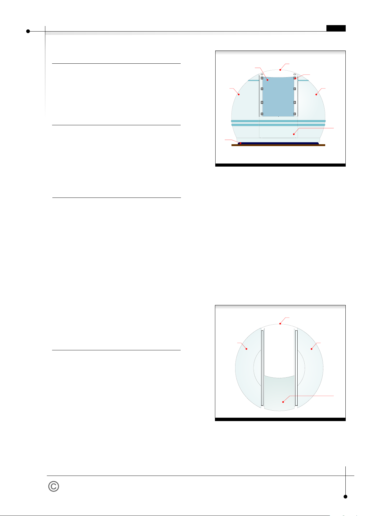
Fig. 2 - Dome's diagram view from above
A. Left side wall panel
B. Right side wall panel
D. Back panel
E. Shutter
EN
How to start?
F
Assembly preparation.
View instruction photos
from attached CD-Rom.
Action Order.
Tools required
to set-up the dome:
1. Make sure you have all dome's parts
2. Prepare the place for dome's assembling. You will
need a flat place, approx. 5.0x5.0m.
1. Read this manual understandingly.
2. Set-up base ring.
3. Screw together rotating parts of the dome (both
sides, front and back panels).
4. Place the dome onto base ring.
5. Fit the shutter.
6. Check if the dome turns round loosely, and if the
shutter is opening and closing easily.
7. Fit cog-rim for cog-wheel drive.
8. Fix rotary drive shield.
9. Fit rotary drive and shutter motor, Home Sensor, the
encoder, encoder's cleaning tape, limit switches,
inverters, shutter cable box and ScopeDome card.
10. Connect all elements according to diagram.
11. Check limit switches action
12. Install dome's drive software.
1. Automatic screwdriver with x-shaped ending
2. A small screwdriver with flat ending
3. Knife or scissors for cutting wires
4. Inbus keys set
5. Hex keys, screw keys set
6. Driller and drills
7. Universal meter
and suitable tools.
Each photo is worth more then thousand words.
Lock through photos before assembly.
They can be found at: "Assembly instruction
photographs"
An additional person to help is required when fitting-up
the dome.
If you plan to mount the dome on the base ring manually,
you will need the assistance of four strong adults.
Fig. 1 - Dome's diagram front view
A. Left side wall panel
B. Right side wall panel
C. Front panel
D. Back panel
E. Shutter
F. Shutter securing holders
G. Base ring

ScopeDome.com
2010 Slupsk - Poland
Base ring fitting
D
A
B
C
Fig. 3 - Base ring scheme
A. Base ring element
B. Ring connecting edges.
C. Base ring main roller
D. Base ring mounting flange
A
B
C
D
E
G
H
F
Fig. 4 - Base ring section
A. Dome's side wall panel
B. Base ring
C. Shield
D. Shield mounting plate
E. Shield roll
F. Base ring side roll
G. Base ring main roll
H. Dome's driver ring
page 3
Base ring fitting
Dome's assembly
1. Put together and screw all four pieces of the base
ring. Seal side joints with frost-resistance silicone,
preventing wather from getting inside the dome.
2. Coat the bottom of base ring with frost-resistance
silicone. Place the base ring onto observatory's curb-
plate (or other basis). Seal all edges of base ring
with frost-resistance silicone too.
3. Check if the ring base forms an ideal circle. If it's not
perfectly round - adjust it carefully by hitting with
gum hammer.
4. Screw the inner and outer ring flange with the
observatory's crown rim, using 16 bolts.
1. Put one of the side panel and front panel side by
side. Screw on both panels nearby driving ring.
2. Add the second side of the dome to previously
connected elements. Screw on the second side of
the dome with its front panel nearby the driving ring
3. Insert the rear panel of the ring between two sides
and screw on rear module of the ring.
4. Adjust the joints of the driving ring with carpentry
holder and finally screw on bolts of all joints of the
driving ring.
5. Screw on all the bolts of the dome's front.
6. Put on the back panel on the sides, matching the
holes. If the holes do not match perfectly, just slightly
drill them up. If the dome's back panel does not
cover side panels, just slightly stretch the dome's
sides inwards while holding their tops. Screw on the
dome's back.
Tip:
Tip:
A carpentry holder will be very helpful during dome's
mounting. It will help to adjust the levels of the driving
ring with particular parts of the dome. First connect each
section of the dome with loose bolts, and then using a
carpentry holder - adjust the neighboring elements of the
dome. Finally - tighten the bolts firmly.
Do not forget to put the washers on both sides of all
bolts connecting the elements of the dome.
EN

ScopeDome.com
2010 Slupsk - Poland
3
2
4
1
5
Sequence of dome’s elements fitting-up
Fig. 5 - Sequence of dome's elements fitting-up
1. Left side panel
2. Front panel
3. Right side panel
4. Rear driving ring module
5. Back panel
6. Shutter (invisible)
page 4
EN
ScopeDome.com
2010 Slupsk - Poland
Placing a dome onto base ring
Base ring
Placing a dome onto base ring
page 5
A
B
C
E
Fig 6 - Cog-rim of rotary drive.
A. Cog-rim
B. Encoder
C. Encoder support
D. Elastic pads (washers)
E. Dome
A
B
C
fig 7
A.Last segment of
cog-rim
B. Cog-rim
C. Dome
D
3 mm
Placing the dome
onto base ring
Rotary drive
cog-rim assembly
1. Lift the dome and put it down onto the rollers of the
base ring.
2. Check if the dome turns round easily; turn it several
times around the axis.
3. After you fit the cog-rim drive, screw on drive shields
to the base ring. Check if the upper rollers of the
shields do not press the driving ring too much. There
should be approximately a 1 mm distance between
roller and the ring.
1. Place the cog-rim according to fig. 6 scheme.
2. Start with longer (1-meter long) elements. Screw
each with the dome using at last four screws. Cog-
rim shall stick out by approx. 3mm over dome's
edge.
3. Do not tighten the screws at the beginning, leave
some margin to allow free movement of cog-rim.
4. After fixing 7 longer segments, the last, short one
shall be squeezed in e.g. pushed in with some force.
Try to bend it forward into dome's interior and then
just push the bulge to border on the dome
(see fig 7).
5. Align and level cog-rim parts, fit joints focusing on
cog geometry.
6. Tighter all screws.
Tip:
Tip:
A properly assembled dome
should turn round by a finger pressure
applied to the front panel of the dome.
When fitting up the encoder, notice if it does not abrade
the cog-rim. It is very easy to destroy it while rotating the
dome.
EN

ScopeDome.com
2010 Slupsk - Poland
Fitting up the shutter.
Action sequence.
1. Unscrew rear movement limiters.
2. Fix eight holders securing the shutter from being
dragged away by strong wind (four holders at each
side).
3. Screw on the decorative handles at the front and
rear of the shutter.
4. Put the shutter onto the dome.
5. Fix limit switches clamp.
6. Screw on the rear movements limiters.
Mind correct orientation of shutter front and back.
Shutter front has a specific incision which matches front
panel of the dome. Securing holders shall be screwed on
in a way to touch aluminum guide rails very slightly.
These rails shall be under holders rollers. It is more
convenient to start shutter assembly from the dome's
back. Properly mounted shutter has to open and close
without resistance nor abrasion.
The shutter without engine tends to fall down (it is not
balanced well). Since you have automatics installed, the
shutter is restrained by the driving cog-wheel. It is
especially dangerous when the shutter falls down during
opening.
The shutter shall be opened and closed in two steps -
first grab the shutter at the front, open it just halfway
and check if it does not start to fall down. Then walk
around to the dome's back and open the shutter to the
end position, holding it by the rear handle.
Tip:
Fig 8 - Shutter mechanics
A. Securing holders
B. Limit switches pressure plate
B
C
F
E
D
A
D
Top View
Fig. 9 - Shutter scheme
A. Dome's front panel
B. Shutter
C. Dome's back panel
D. Limit switch Close
E. Limit switch Open
F. Limit switches pressure plate
G. Shutter drive
H. Decorative handle
I. Drive cog-rim
Fitting up the shutter.
page 6
G
H
H
A
A
B
I
EN
ScopeDome.com
2010 Slupsk - Poland
Shutter drive assembly
A
C
B
D
E
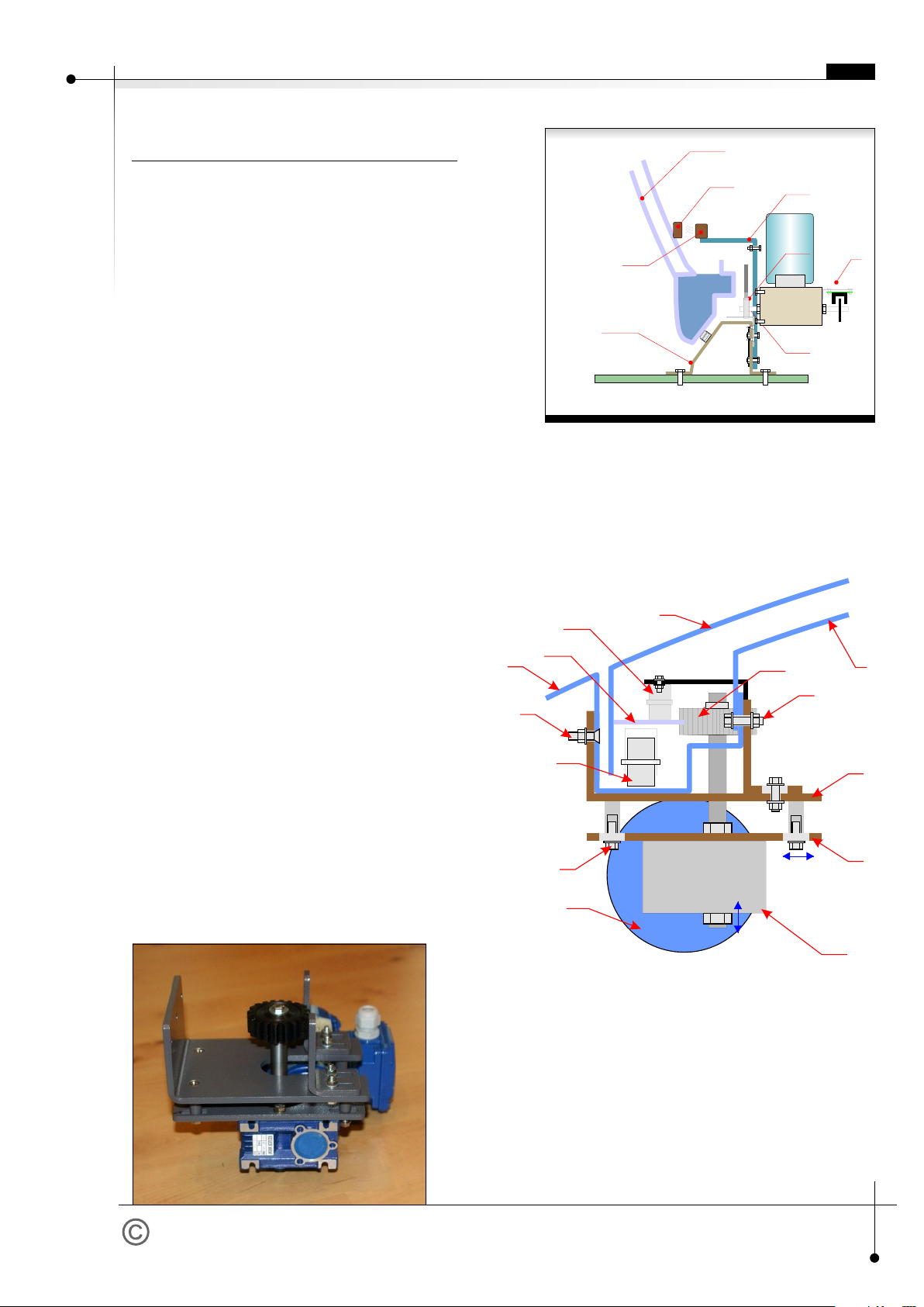
Fig. 10 - Encoder module on motor axis
A. Dome's side panel
B. Base ring.
C. Shield holder/support
D. Home sensor magnet
E. Home sensor contractron
F. Encoder module
page 7
G
F
E
D
F
C
B
A
G
H
I
J
J
K
L
M
L
B
A
C
M
Fig. 11 - Shutter drive.
A. Motor/Engine
B. Motoreductor (i=80)
C. Cog-wheel
D. Shutter holder roller
E. Cog-rim
F. Shutter's main roller
G. Dome's side panel
H. Shutter panel
I. Dome's back panel
J. Bolts/Screws fastening the motor
K. Roller pressure adjustment screws
L. Motor main holder
M. Motor module support.
fig. 12 - Shutter drive.
Shutter drive assembly
Action sequence.
1. Screw on motor main holder (L) at dome's top with
the use of five screws.
2. Fix the cog-wheel (C) in drive motor module (M).
3. Screw on slightly drive motor with main shutter
holder in a way that the cog-wheel would not touch
shutter's cog-rim.
4. Adjust cog-wheel height so that cog-rim is at its
middle point.
5. Fix end switches.
6. Test limit switches operation trying to set them active
at approx. 2cm before full open/close of the shutter.
7. Press and tighten cog-wheel to shutter's cog-rim and
screw on the bolts (K) fastening motor module.
8. Install motor and limit switches wiring.
9. Open and close the shutter several times using
ScopeDome USB Card.
10. If the cog-wheel slips off cog-rim - stop the shutter at
this point. Loosen screws fastening the motor
module, then tighten the cog-wheel to cog-rim hitting
2X motor mounting plate with a hammer. Next screw
on firmly four bolts fastening the motor module.
11. Test shutter drive operation again.
12. Check if the shutter power cable does not brush
dome's engine during its revolution.
Shutter motor is powered by 14-core cable. Its both ends
shall be fixed firmly - as not to be teared out if the dome
proceeds too many turns. The cable shall be placed in a
way it would not brush the dome's engine.
EN
F

ScopeDome.com
2010 Slupsk - Poland
Electronics and driving systems fittings
F
G
A
C
H
D
B
I
J
Fig. 13 - Dome's driving motor system
scheme
A. Dome's side wall panel
B. Base ring
C. Cog-rim drive shield
D. Cog-wheel
E. Cog-rim
F. Motor ( engine)
G. Motor reductor (gear) (1/50)
H. Engine's mounting plate
I. Driving ring
J. Driving ring bolt holes
C
D
E
F
A
B
Fig.14 - Electrical installation diagram
A. Base ring
B. Cog-rim drive shield support/holder
C. Main power supply box
D. ScopeDome Card
E. Driving motor system with roller
F. Pier (a telescope basis)
page 8
E
Electronics and driving systems
fittings
Tip:
Tip:
- Do not install shutter driving wire cables until you test
the shutter motor system end switches action and
the whole electronics.
- Before you install the drivers and electrical
components, it is recommended to wash the dome
using a garden hose. Without this operation
removing the remains and debris will require much
more effort.
1. Fit encoder sensor (see fig 6). Start to rotate the
dome carefully, focusing your attention on possible
cog-rim abrasion. Encoder could be damaged very
easily if such abrasion appears.
2. Fit contactron "home" on drive shield.
3. Fit end switches on the front and the top of the
shutter window.
4. Fit the end switches pressing plate on the shutter in
a way that limit switches activate at about 2 cm
before full closing or full opening of the shutter.
5. Put contactron "home" magnet on the dome's back
at the distance from contactron "home" allowing
contactron's switches to be active as briefly during
the dome's rotation, as possible.
6. Stick encoder cleaning tape to cog-rim (see fig 10) at
contactron magnet (Home Sensor) height.
7. Fit the cable box on the rotary part of the dome.
8. Fit the ScopeDome Card on the one of the drive
shield or on scope's pier.
9. Fit the dome's driving motor on the drive shield
opposite to ScopeDome Card.
10. Connect all elements and wiring according to the
electrical diagram of the observatory.
11. Test driving motors and end switches.
12. Install control software and calibrate the dome.
(Calibration description in Help menu).
Limit switches control wiring and illumination wiring can
be lead through the holes previously drilled in the side
reinforcements close by shutter window.
EN
Table of contents
Other ScopeDome Telescope manuals


Popular Telescope manuals by other brands

Protocol
Protocol Telescope with Tripod instruction manual

National Geographic
National Geographic NT114CF instruction manual

Celestron
Celestron 80LCM manual

Celestron
Celestron National Park Foundation TravelScope 60 instruction manual

SIGNIFY
SIGNIFY EA2206 instruction manual

Discovery
Discovery Spark EQ Series user manual

Celestron
Celestron Advanced VX 91519 instruction manual

Barska
Barska 300 Power Starwatcher Telescope 40070 Directions for use

Polaris
Polaris Meade 21600X quick start guide

Barska
Barska Encounter AB11190 operating instructions

Bresser
Bresser EQ Series instruction manual

Meade
Meade LX200 CLASSIC instruction manual


