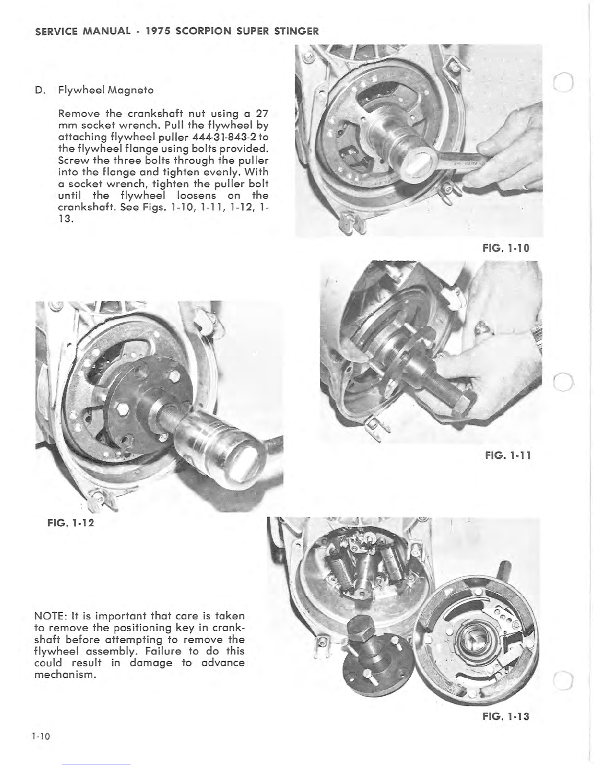
SCORPION Super Stinger 1975 User manual

~···-
io·
1975
Scorpion
Super
Stinger
Service
Manual
Engine
Section
1

SERVICE
MANUAL-
1975
SCORPION
SUPER
STINGER
ENGINE
SYSTEM
Functional
Description:
2-CYCLE ENGINE FUNDAMENTALS
The
Rockwell
2-cycle
air
-
coo
l
ed
gasoline
engine,
particularly
the
axial
fan-cooled
twin
cylinder
engine,
has
become
very
popular
today
for
snowmobiles.
It
is
uniquely
qualified
for
this
ap-
plication
because
of
its
high
power
output,
light
weight
and
ease
of
lubrication,
with
fewer
moving
parts
than
other
conventional
2-cycle
and
4
-c
ycle
engines.
However,
in
order
to
get
the
best
possib
le
use
and
ensure
that
it
retains
its
high
degree
of
dependability
and
endurance,
it
must
receive
proper
care
and
maintenance.
Therefore,
it
is
necessary
for
us
to
know
something
about
the
basic
fundamentals
of
.
this
engine
and
how
it
functions.
OPERATION
The
Rockwell
2-cycle
Twin
Cylinder
engine
is
of
the
loop-scavenged
third
port
type,
the
most
wide
ly
used
design
today.
It
uses
a
mixture
of
gasoline,
oi
l
and
air
for
combustion,
lubrication
and
cooling.
It
fires
on
every
stroke
of
each
piston.
There
ore
two
power
strokes
for
every
revolution
of
the
crankshaft.
As
the
piston
moves
upward
in
the
cylinder
it
draws
the
fuel/air
mixture
into
the
crankcase
through
the
intake
manifold
while
at
the
same
time
compressing
fuel
that
has
been
forced
into
the
combustion
chamber.
See Fig.
1-1
A.
As
the
piston
nears
top
dead
center
the
spark
plug
is
fired
and
the
compressed
fuel/air
mix-
ture
burns
and
expands
thereby
forcing
the
piston
downward
on
a
power
stroke.
As
the
downward
stroke
of
the
piston
turns
the
crankshaft,
it
also
starts
to
compress
the
fuel/air
mixture
in
the
crankcase
and,
simultaneously,
opens
the
exhaust
port
and
cl
oses
the
intake
port.
See
Figs. 1-1 B &
C.
1-2
I
NTAKE
0
EXH/UST
TRANSFER
FIG.
1-1

SERVICE
MANUAL· 1975
SCORPION
SUPER
STINGER
After
the
exhaust
port
is
fully
open
and
the
in-
take
port
is
fully
closed,
further
piston
travel
starts
to
open
the
transfer
ports.
The
com-
pressed
fuel/air
mixture
from
the
crankcase
then
travels
up
the
transfer
ports
and
into
the
combustion
area.
After
most
of
the
burned
exhaust
gases
have
left
the
cylinder,
an
incoming
charge
of
fuel/air
mixture
scavenges
the
combustion
area
giving
it
a
fresh
charge
and
the
cycle
is
then
repeated.
SeeFig.l-1
D.
Because
lubrication
is
dependent
on
the
m1xmg
of
oil
and
fuel,
it
is
extremely
important
that
good
quality
oil
and
gasoline
are
properly
mixed.
The
proper
ratio
of
oil
to
gasoline
will
prevent
possible
engine
overheating,
piston
or
cylinder
scoring,
or
eventual
engine
seizure.
Too
much
oil
and
not
enough
gasoline
can
lead
to
incomplete
combustion,
fouled
plugs,
carbon
build-up
and
muffler
clogging.
l-3

SERVICE
MANUAL·
1975
SCORPION
SUPER
STINGER
EXHAUST
SYSTEMS
SELECTION
Selection
of
an
exhaust
system
(including
exhaust
manifold,
intermediate
pipes,
elbows
and
muffler),
is a
result
of
thorough
test
procedures
involving
measurement
of
fuel
con-
sumption,
horsepower
and
noise
level.
Contrary
to
popular
belief,
the
exhaust
system
is
not
only
for
quieting
the
engine,
but
also
serves
to
in-
crease
horsepower
output
(by
as
much
as
25%).
Changes
made
to
the
original
equipment
exhaust
system
by
changing
any
component
in
the
system
can
result
in
loss
of
power
and/or
severe
engine
damage.
For
these
reasons,
intermediate
lengths
of
pipe
between
the
cylinder
and
the
muffler
are
particularly
critical.
TUNED MUFFLERS
Tuned
mufflers
allow
the
engine
to
exhaust
its
spent
charge
int
o
an
adequate
volume
and
properly
matched
muffling
system.
More
im-
portant,
the
mufflers
that
are
tuned,
incorporate
designs
that
suck
the
exhaust
gas
from
the
cylin-
der
allowing
fuel
and
air
to
rapidly
replace
it
and
also
"cram"
over-scavenged
fuel
and
air
mixture
from
the
exhaust
pipe
back
into
the
cylinder
using
sound
waves
and
sound
energy.
This
is
ac-
complished
at
the
speed
of
sound
which
allows
the
engine
to
produce
higher
torque
at
higher
RPMs.
1-4
Donaldson
FIG.
1·2
n
Tuning
Courtesy
of
Dona
l
dson
Muffler
Co
)
FIG.
1·3

SERVICE
MANUAL·
1975
.SCORPION
SUPER
STINGER
HOW
TUNING
WORKS
The
megaphone
effect
of
the
expanded
intake
tube
scavenges
exhaust
gas
from
the
cylinder
allowing
rapid
replacement
of
the
fuel/air
mix-
ture
from
the
crankcase.
Reflected
sound
waves
and
sound
energy
stop
over-scavenging
and
return
fuel/air
mixture
to
the
cylinder.
It
gives
a
supercharging
effect
even
though
it
operates
from
the
exhaust
rather
than
the
intake
side.
Over-scavenging
is
also
retarded
by
moderate
muffler
back
pressure.
Silencing
is
accomplished
after
power
is
maximized
by
acoustical
packing
in
the
resonator
outlet
tube
plus
chambering
and
baffling
which
gives
an
effective
2-pass
muffler
design.
1·5

SERVICE
MANUAL-
1975
SCORPION
SUPER
S
TING
ER
TABLE OF
SPECI
FICATIONS
ENGINE MODEL
DESCR
IPTION 2F
440-
3 2F
400
-8 2F
440-8
2.
658"
2.559"
2.
658"
BORE
(67.5mm)
(
65.0mm)
(67.5mm)
J
STROKE
2.362"
(60mm)
DISPLACEMENT IN cc
428
398
428
COMPRESSION RATI
ON
(actual)
12.5:1 12:1 12:1
I
GNITION
SYSTEM Bosch
Flywhe
el
Magneto
LIGHTING COIL
VOLTAGE
AND
OUTPUT
12V
75W
1
2V
150W
12V
150W
*TIMING
BEFORE
TDC
(CENTRIFUGAL .
102
-
.112
.102-.112
.1
02-
.
112
WEIGHT
ADVANCED)
TIMING
BEFORE
TDC (CENTRIFUGAL .0
18"
to
.
020"
.018
"
to
.020"
.0
18"
to
.020"
WEIGHT RETARDED)
BREAKER POINT
GAP
.014"to
.01
6"
SPARK
PL
UG THREAD
14mm.
x 1
.25
-
3/
4"
reach
.020"
.
020"
.020
"
SPARK PLUG
GAP
(0.
5mm
.)
(0.5mm.) (0.5mm.)
SPARK PLUG-BOSCH
(ORIGINAL
W260T2
W260T2
W260T2
EQUIPMENT)
TYPE
OF
ENGINE
COOLING
Axia
l Fl
ow
Fan
ROTA
TION
OFCRANKSHAFT
Counterclockwise
(PTO
side)
CARBURETOR
Wa
l
bro
FUEL/OIL RA
TI
O
As
Specified
on
Scorpion
Oil
Conta
i
ner
GASO
LI
NE
95
octane,
mini
mum
(lead
free
not
accep
t
ab
l
e)
TYPE
OF
O
IL
Special 2-Cycle
Snowmobi
le
Oil
*
Do
no
t
exceed
indicated
advance,
as
this
will
result
m
severe
engme
damage.
1-6

0
TORQUE SPECIFICATIONS
CYLINDER HEAD NUTS
CYLINDER B
ASE
NUTS
FlYWHEEL NUT
INTAKE
MANIFOLD
NUTS
FAN
HOUSING
SCREWS
FAN
WHEEL NUT
RING GEAR
SCREWS
(6mm.)
RING GEAR
SCREWS
(8mm.)
SERVICE
MANUAL-
1975
SCORPION
SUPER
STINGER
TABLE OF SPECIFICATIONS
-8 -9 2F-
440-3
2F-400-6 2F-440-5
19 28
to
32
ft./lbs.
16
to
18
ft./lbs.
44
to
50
ft./lbs.
56
to
72
ft./lbs.
56
to
72
ft./lbs
.
16
to
18
ft./lbs.
16
to
18
ft./lbs.
22
to
24
ft./lbs.
6
to
7
ft./lbs.
not
applicable
not
applicable
10
to
12
ft./lbs.
not
applicable
10
to
12
ft./lbs.
Tightening
Sequence
for
Cylinder
Base
Nuts
0 0 8 0
PTO
SIDE
0
G)
0 8
Tightening
Sequence
for:
Cylind
er
Head
Nuts,
Fan
Housing,
Ring
Gear
Flange,
Intak
e
Manifold
and
Recoil
Starter
Clamps
0
8 0 0
'74-
'75
'74
-
'75
®
290s
400s
340s
440s
AI
I
previous
G)
models
®
0 0
CD
1-7

SERVICE
MANUAL
-
1975
SCORPION
SUPER
STINGER
ROCKWELL
TWIN
CYLINDER ENGINES
MODELS 2F-400-.8
DISASSEMBLY
2F-440-8
A.
Recoil
Starter
Remove
four
(4)
screws
holding
the
recoil
assembly
to
the
fan
housing.
See Fig. 1-4.
See
pages
1-
28
A,
B,
C
for
recoil
starter
disassembly.
B.
Lower
Fan
Pulley
and
Carrier
Assembly
l-8
Remove
the
three
(3)
hex
head
bolts
on
the
carrier.
Remove
carrier,
lower
pulley
assembly
and
V-belt.
See Figs. 1-5, 1-6.
FIG. 1-4
A
(.:
FIG. 1-5
FIG. 1-6

c
SERVICE
MANUAL
· 1
975
SC
ORPION SU
PER
S
TI
NGER
C.
Upper
Fan
Belt
Pulley
Assembly.
Insert
a
3/
16"
dri
ll
or
a
suitable
punch
through
the
indexing
hole
into
the
im-
pe
ll
er
body.
With
a
17
mm
socket
wrench,
remove
the
fan
nut
,
lock
washer
,
pulley
halves
and
spacers.
See
Figs. 1-7
,1
-8,1-9.
FIG. 1-8
FIG. 1-7
FIG. 1-9
1·9

SERVICE
MANUAL
-
1975
SCORPION
SUPER
STINGER
D.
Flywheel
Magneto
Remove
the
crankshaft
nut
using
a
27
mm
socket
wrench
.
Pull
th
e
flywheel
by
attaching
flywheel
puller
444-31-8
43
-2
to
the
flywheel
flange
using
bolts
provided.
Screw
the
three
bolts
through
the
puller
into
the
flange
and
tighten
evenly.
With
a
socket
wrench,
tighten
the
puller
bolt
until
the
flywheel
loosens
on
the
crankshaft.
See
Figs.
1-10,
1-11, 1-12, 1-
13.
FIG. 1-12
NOTE:
It
is
important
that
care
is
taken
to
remove
the
positioning
key
in
crank-
shaft
before
attempting
to
remove
the
flywheel
assembly.
Failure
to
do
this
could
result
in
damage
to
advance
mechanism.
1-
10
()
FIG. 1-10
Q.
FIG. 1-11
FIG. 1-13

SERVICE
MANUAL
·
1975
SCORPION
SUPER
STINGER
E.
Intake
Manifold
Assembly
Remove
the
four
(4)
intake
manifold
nuts
and
washers.
Remove
manifold
assembly
and
insulators.
See Figs. 1-14,
1-15.
.0,0
•-'•
,;
<i
*:
oo
00
FIG.
1-14
FIG. 1-15
1-l l

SERVICE
MANUAL
-
1975
SCORPION
SUPER
STINGER
F.
Fan
Housing and
Armature
Plate Assembly
Remove
screw
holding
spark
plug
wire
bracket
to
fan
housing.
With
a
socket
type
5
mm
Allen
wrench
and
impact
driver,
remove
the
four
(4)
mounting
bolts
holding
fan
housing
to
crankcase.
(See Fig.
1-16).
Remove
fan
housing
from
crankcase
(See
Fig. 1-
17).
Unplug
connector
housing
coil
wires.
(Note
color
coding
of
wires.)
Remove
armature
plate
assembly
and
wires,
as
a
unit,
from
fan
housing.
1-12
FIG. 1-16
FIG. 1-17 )

n
(
SERVICE
MANUAL
·
1975
SCORPION
SUPER
STINGER
Remove
the
fan
by
tapping
the
end
of
fan
shaft
with
a
soft
hammer.
With
a
flat
punch
and
hammer,
tap
the
inner
race
of
the
fur-
thest
bearing
in
the
housing.
See Figs. 1-18,
1-19, 1-20.
FIG. 1-18
FIG. 1-19
'
\..._
FIG. 1-20
l-13

SERVICE
MANUAL
-
1975
SCORPION
SUPER
STINGER
G.
Remove
spark
plugs
with
s
park
plug
wrench.
(See Fig. 1-21.)
H.
Cylinder
Heads
Remove
cy
lind
er
head
nuts
with
a
13
mm
socket
wrench.
Mark
cylinder
heads
before
removal
from
cylinder.
Remove
and
discard
gaskets.
See Fig.
1-22.
I.
Cylinders
Remove
the
e
ight
(8)
cylinder
base
nuts
using
a
13
mm
socket
wrench
and
remove
the
eight
(8)
spring
washers.
The
cylinders
may
be
removed.
See
Fig. 1-23.
NOTE:
IMP
0 R
TAN
T
If
removal
of
cy
linder
s
only
is
required,
care
must
be
taken
that
the
crankcase
seal
is
not
disturbed.
The
removal
of
the
PTO
cylinder
will
allow
the
placement
of
two
bolts
and
nuts
with
flat
washers
to
apply
constant
pres-
sure
to
crankcase
assembly.
Bolts
should
be
placed
in
the
cen
t
er
two
holes
(adjacent
to
the
fan
side
cy
lind
er).
See Fig. 1-31.
The
second
cylinder
may
now
be
removed.
1-
14
FIG. 1-21
FIG. 1-22
FIG. 1-23

r
n
c
SERVICE
MANUAL
·
1975
SCORPION
SUPER
STINGER
J.
Piston
and
Wrist
Pin
With
needle
nose
pliers,
remove
circlips
from
pistons.
Heat
the
piston
with
a
heat
gun
or
propane
torch.
Heat
only
to
the
point
where
piston
may
still
be
held
in
hand.
Push
the
pin
out.
K.
To
separate
the
crankcase
halves,
hold
upper
portion
of
crankcase
assembly
in
one
hand,
lifting
slightly
and
tap
the
end
of
the
crank-
case
with
a
soft
hammer.
The
crankcase
will
separate
and
the
crankcase
may
be
removed.
See Fig. 1-24.
\ .
.,
.
..
1
·
...
·'
("""'!)
i
FIG. 1-
24
1-15

SERVICE
MANUAL
•
1975
SCORPION
SUPER
STINGER
L.
Crankshaft
Bearings
1-16
To
remove
crankshaft
end
bearings,
use
bearing
puller
444
-31 -
807-0.
See Figs. 1-25,
1-
26,
1-27.
Slip
the
puller
half
shells
around
the
outer
bearing
race
and
around
puller
assembly.
Slide
the
retaining
ring
over
the
half
shells.
Using
two
(2)
27
mm
wrenches,
turn
the
center
bolt
clockwise
with
one
wrench
and
use
the
second
wrench
to
hold
the
puller
body.
Before
removing
the
PTO
side
crankshaft
bearing,
insert
a
1/2"
20
UNF
bolt,
1
/2"
long,
to
protect
the
internal
thread
of
the
crankshaft.
FIG. 1
-25
FI
G.
1-26
FI
G.
1
·27

SERVICE
MANUAL
•
1975
SCORPION
SUPER
STINGER
ASSEMBLY
( A.
Crankshaft
Bearings.
(
Heat
crankshaft
bearings
in
oil
(or
oven)
to
approximately
180
degrees.
Slide
bearing
on
crankshaft.
B.
Crankcase.
Inspect
and
clean
both
halves
of
crankcase.
The
proper
sealant
material
such
as
Per-
matex
Hy
-
Tack
Spray
should
be
now
sprayed
on
crankcase
sealing
surfaces.
See Fig. 1-29.
Before
installing
crankshaft
into
crankcase
lower
half
of
it
will
be
necessary
that
all
bearing
outer
surfaces
be
wiped
clean
of
foreign
material
so
that
proper
sealing
will
occur.
After
installing
PTO
thrust
washer
and
oil
seal
(inside
groove
of
oil
seal
coated
with
light
grease)
place
the
crankshaft
carefully
into
the
lower
crankcase
half
and
properly
position
all
components.
See Figs. 1-
30.
Placement
of
the
upper
crankcase
half
may
now
be
made.
Be
certain
that
the
center
seal
is
lined
up
with
the
crankcase
split
line.
Tap
upper
crankcase
half
to
seat
with
lower
half.
FIG. 1-28
FIG. 1-29
FIG. 1-30
l-17

SERVICE
MANUAL
·
1975
SCORPION SUPER STINGER
Install
two
crankcase
holding
bolts
in
the
center
holes
of
the
PTO
side
of
crankcase.
(Fig.
1-31)
Tighten
finger
tight.
C.
Piston
,
Cylinder
and
Cylinder
Heads
The
pistons
must
be
clean
and
free
from
car
-
bon
deposits
and
the
piston
rings
must
fit
freely
in
their
grooves.
Rings
are
marked
for
proper
side
up.
The
arrow
on
the
crown
of
pistons
must
point
toward
exhaust
side
of
engine.
Piston
pins,
needle
bearings,
check
plates
and
circlips
may
now
be
installed,
ac
-
cording
to
the
procedure
below.
(Always
use
new
circlips.)
See
Figs. 1-32, 1-
33,
1-34, 1-
35.)
CIRCLIP
OPENING
HERE---'
FIG.
1-33
1·18
J
FIG.
1-31
()
FIG.
1-32
J

SERVICE
MANUAL
·
1975
SCORPION
SUPER
STINGER
1.
Oil
the
piston
pin
end
bearings.
2.
Install
one
circlip
in
piston.
3.
Heat
the
piston
sufficiently
to
allow
pin
to
push
into
piston
and
install
pin.
4.
In
stal
l
second
circlip.
(See Fig.
1-33
for
correct
orientation
of
circlips.)
0
FIG.
1·34
FIG. 1-35
1-19

SERVICE
MANUAL
·
1975
SCORPION
SUPER
STINGER
In
stall
base
gaskets
on
th
e
cy
lind
er
studs
and
position
against
the
cy
linder
flanges
(see
Fig.
1-
36).
With
the
use
of
a
ring
compressor,
lower
cy
lind
ers
one
at
a
time
over
the
pistons
. Ins
tall
base
washers
and
nuts
finger
tight.
See
Fig.
1-
37,
1-38.
Temporarily
install
the
intake
manifold
without
gaskets
and
tighten
manifold
nuts
to
sixteen
(16)
to
eighteen
(18)
foot
pounds.
See
Fig.
1-
39.
Cy
lind
er
base
nuts
may
now
be
torqued
to
sixteen
(16)
to
eighteen
(18)
foot
pounds
as
outlined
on
specification
page.
The
proper
piston
height
can
be
measured
at
the top
of
the
cylinder
.
The
edge
of
the
crown
of
the
piston
must
not
protrude
above
the top
of
th
e
cylinder
with
the
piston
in
the
top
dead
center
position.
If
the
piston
does
protrude
above
the
cylinder,
a
thicker
base
gasket
must
be
used.
See
specification
page
for
dimensions
and
color
coding.
It
is
important
that
only
one
cylinder
at
a
time
be
adjusted
or
the
crankcase
will
separate
and
lose
it's
seal.
l -
20
FIG. 1·36
FIG. 1-37
(
FIG. 1-38
Other SCORPION Snowmobile manuals
Popular Snowmobile manuals by other brands

Lynx
Lynx BRP REX2 Adventure LX 600 ACE Operator's guide

Ski-Doo
Ski-Doo Safari 1990 Operator's manual

Ski-Doo
Ski-Doo 1980 citation 3500 Operator's manual

BOMBARDIER
BOMBARDIER ski-doo elan 250 1980 Operator's manual

BOMBARDIER
BOMBARDIER Ski-Doo Alpine 74 1959 owner's manual

BOMBARDIER
BOMBARDIER ski-doo Nordic 640ER 1974 owner's manual