Sea King 9815-RJ User manual
11200 Hampshire Avenue South, Bloomington, MN 55438-2453
Phone: (800) 982-9920 Fax: (952) 922-8424
www.kingcontrols.com
1315 REV C
Satellite Solutions for Mobile Markets
MEMBER
®
®
Gyro Stabilized Marine Satellite TV System
Model 9815-RJ
Model 9818-RJ
Installation and Operating Instructions


Page 1
TABLE OF CONTENTS
Section Contents Page
1. INTRODUCTION............................................................................................................2
2. DEFINITION OF TERMS...............................................................................................3
3. INSTALLATION.........................................................................................................4-17
4. OPERATION...........................................................................................................18-21
5. AUTOMATIC SATELLITE SWITCHING (DIRECTV®)...................................................22
6. AUTOMATIC SATELLITE SWITCHING (DISH NETWORKTM - EXPRESSVU) ............23
7. CHECK SWITCH PROCEDURE............................................................................24-25
8. TROUBLESHOOTING............................................................................................26-29
9. MAINTENANCE...........................................................................................................30
10. LIMITED WARRANTY .................................................................................................31
DIRECTV®is a registered trademark of DIRECTV, Inc.
Dish NetworkTM is an official trademark of Echostar Communications Corporation.
Bell ExpressVu is an official trademark of Bell Canada.
DVB®is a trademark of the DVB Digital Video Broadcast Project (1991-1996)
IMPORTANT!
The satellite TV market is expanding and changing. The information in this manual was accurate at the
time of printing. If your Sea-King does not operate as outlined in this manual please call King Controls at
(800) 982-9920 or visit our website at www.kingcontrols.com.
Please read this entire manual before beginning the installation.
DISH NETWORK - EXPRESSVU: If you plan to use the Sea-King with Dish Network or ExpressVu
programming, your receiver must be configured.
To configure the DISH receiver, the antenna must be on the ground, dock or motionless platform with no
movement (see pages 24-25).
This Sea-King is factory ready to receive available HDTV programming from DIRECTV Ku band
satellites at 101° and 119°. This Sea-King will also receive available HDTV programming from the
DIRECTV Ku band satellite at 110°, but must include a properly installed HD converter accessory #9747.
It will not receive channels broadcast from DIRECTV’s Ka band satellites at 99° and 103°.
Note: The following upgrade kit is available for this unit:
Upgrade Kit #9747: Enables viewing of HD broadcasts from the DIRECTV 110° satellite.
For more information, call the King Controls Sales Department at (800) 982-9920.
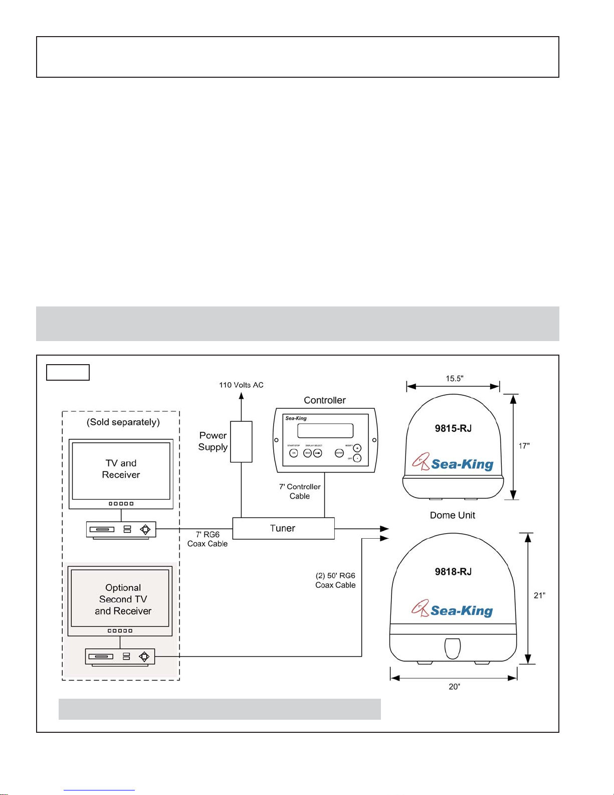
The Sea-King Fully Stabilized Marine Satellite System includes 4 main components (Fig. 1).
Dome (Antenna) Unit Mounted on the vessel. The dish is covered by a protective
dome that keeps operational components free from the
elements.
Controller Located in the vessel. Used to activate and monitor the
system, and access programming and diagnostic information.
Tuner Located in the vessel. Decodes the satellite signal so the
Sea-King locks onto and tracks the correct satellite.
Power Supply Located in the vessel. Supplies proper operating voltage to the
Sea-King.
SECTION 1 INTRODUCTION
Note: A TV, satellite receiver, and program subscription are also required for satellite TV viewing.
(Sold separately.)
Page 2
Fig. 1
Note: Overview only: see Installation Section for wiring schematic.
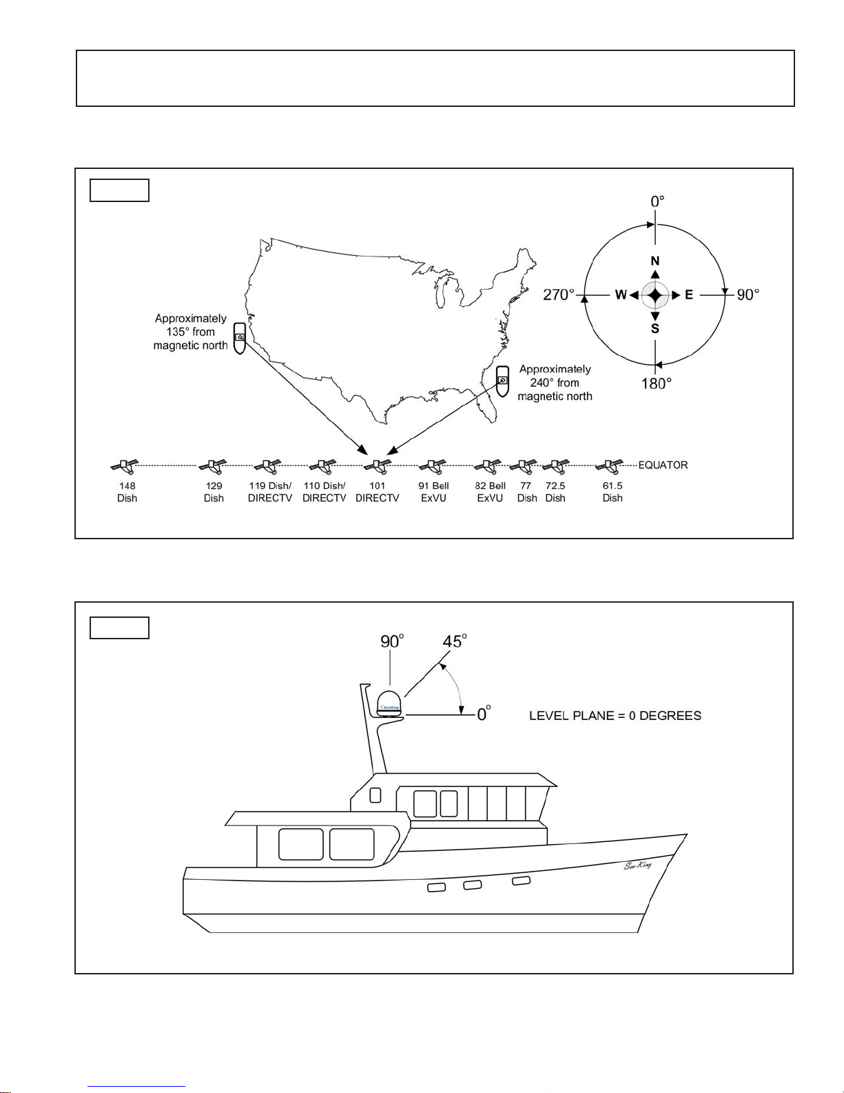
AZIMUTH: Angle in degrees measured clockwise from Magnetic North (0°) (Fig. 2).
SIGNAL STRENGTH: Intensity of electronic signal received from the satellite transmission.
SECTION 2 DEFINITION OF TERMS
Fig. 3
ELEVATION: Angle in degrees measured from a level plane (Fig. 3).
Page 3
Fig. 2
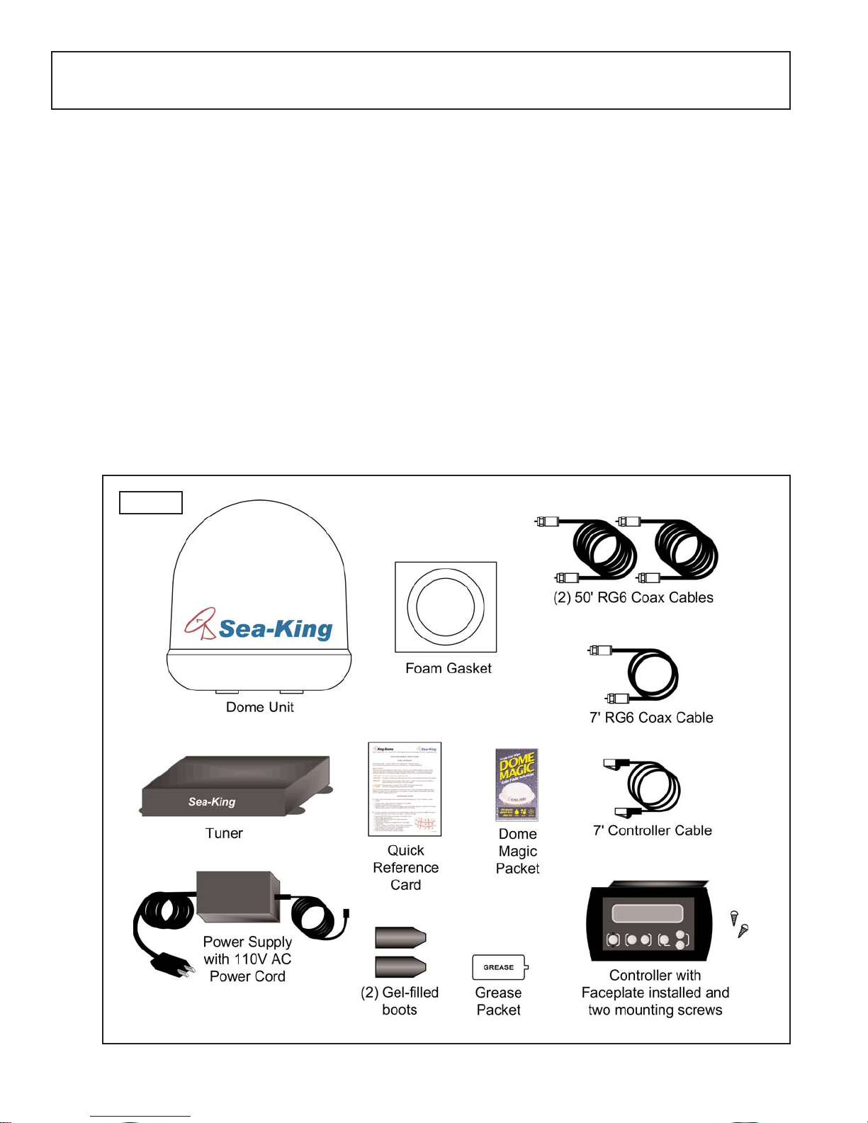
KIT CONTENTS
1. Unpack and identify all components (Fig. 4).
Page 4
SECTION 3 INSTALLATION
TOOLS AND MATERIALS REQUIRED
1. Read thru the instructions and make sure you have all the tools and materials required to
complete the installation, including:
• drill and drill bit set
• tape measure
• 7/16” open end wrench (coax connections)
• 5/32” allen wrench, channel lock or pliers (to remove shipping bolt)
• 1/8” allen wrench or phillips screw driver (to remove dome cover)
• appropriate fasteners and tools to install all components and wiring
• adhesive sealant, compatible with vessel material
Fig. 4
Page 5
DOME LOCATION
1. Select an area on the vessel for the dome unit, keeping in mind the coax cables will enter
the vessel through the surface directly beneath the dome unit. Use the following criteria:
a) The shortest distance between the dome unit and the main satellite receiver is most
desirable.
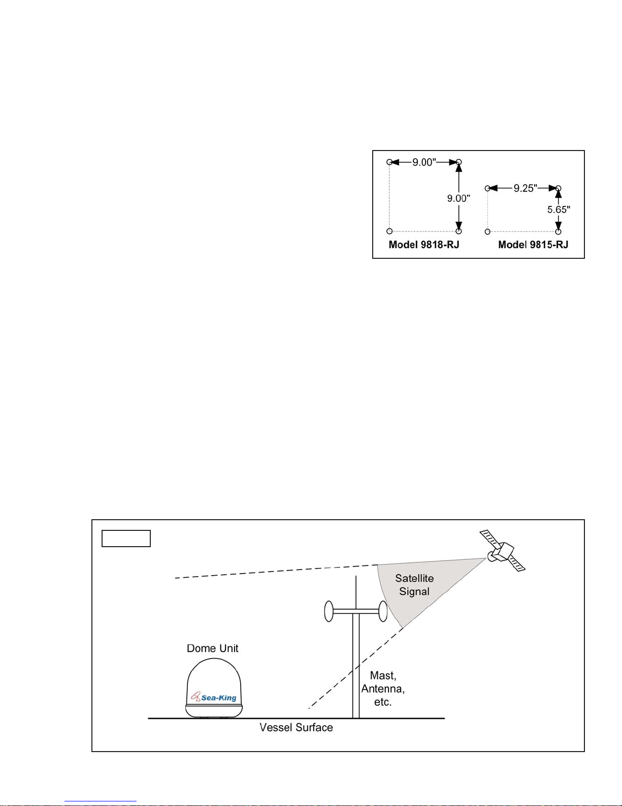
b) The dome unit requires a 16.5” (model
9815-RJ) or 20” (model 9818-RJ)
diameter mounting area on the vessel
surface. You may also use an industry
standard mount. (Call King Controls or visit
www.kingcontrols.com for more information.)
Exact hole spacing is shown at right.
Distances are to centers of holes.
c) The dome unit should never be mounted so that it is tilted more than two degrees
in any direction.
d) Keep the dome unit as far away from the radar as possible, and if possible above
the level of the radar.
e) The dome unit should be mounted as closely as possible to the center of the vessel
(fore-aft and side to side).
f) The mounting surface must be strong enough not to flex under the weight of the
unit or from vessel vibrations.
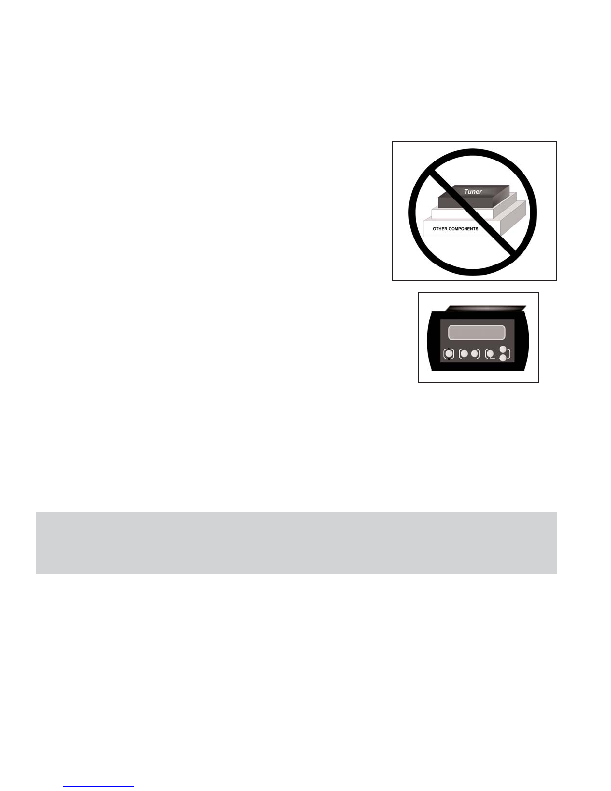
g) There must be no “line of sight” obstructions from this location. Items such as
masts or radar antennas that are too close to the dome unit may prevent the
satellite signal from reaching the dish (Fig. 5).
Fig. 5
Page 6
1. Remove and save the dome cover screws. (Figs. 6A and 6B).
2. Carefully remove the dome cover. Do not allow dome cover to catch on internal
components or wiring.
3. Remove and discard the shipping bolt.
COMPONENT LOCATION
1. Select the location of the internal components using the following criteria:
a) The Controller, Tuner, and Power Supply should be in the same general vicinity of
the main satellite receiver, AND ACCESSIBLE FOR OPERATION AND
MAINTENANCE PURPOSES.
b) The Tuner should not be stacked directly on top of
other electronics. If located in a cabinet or other
enclosure, make sure there is adequate ventilation
around the unit. (If using the Tuner mounting
brackets see page 17.)
c) The Controller should be conveniently located
for the end user. (If using the Wall Mount Faceplate,
see page 16.)
d) All components should be secured so they do not shift or bounce around during
vessel motion.
2. Place the components in the selected areas.
REMOVE SHIPPING RESTRAINTS
Note: Reference appropriate figure on next page for your model number:
Model 9815-RJ: see Fig. 6A
Model 9818-RJ: see Fig. 6B

Page 7
Fig. 6A
Fig. 6B
9815-RJ
9818-RJ
IMPORTANT!
The shipping bolt must be
removed prior to installation.
IMPORTANT!
CAREFULLY remove the
dome cover, tilting it side to
side as necessary to prevent
damaging internal
components.
IMPORTANT!
CAREFULLYremove the
dome cover, tilting it side to
side as necessary to prevent
damaging internal
components.
IMPORTANT!
The shipping bolt must be
removed prior to installation.
Page 8
To verify proper operation of the components, perform a Pre-Installation Check as follows:
1. Place the dome unit in your chosen location and on its mounting pedestal. Temporarily
secure the unit from falling. DO NOT PERMANENTLY MOUNT THE DOME UNIT UNTIL
YOU HAVE COMPLETED THE PRE-INSTALLATION CHECK ON THE NEXT PAGE.
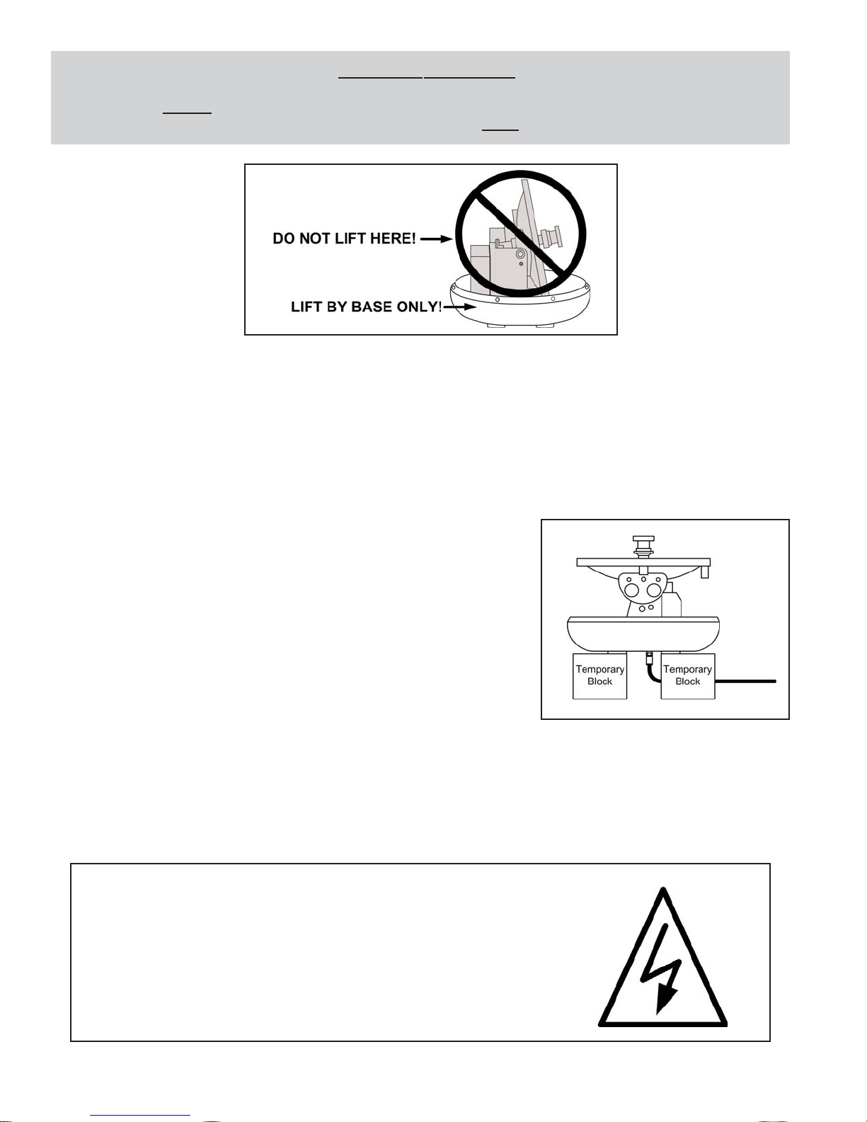
If mounting to the vessel surface, you will need to
temporarily place the dome unit on a pedestal or
blocks to perform the pre-installation check.
IMPORTANT! IF CONFIGURING THE RECEIVER FOR MULTIPLE SATELLITE
SWITCHING WITH DISH NETWORK OR EXPRESSVU, Y0U MUST DO THE
PRE-INSTALLATION CHECK ON A MOTIONLESS PLATFORM SUCH AS THE DOCK
OR GROUND.
EXTREMELY IMPORTANT!
NEVER lift the unit by the LNB assembly, Wave Guide assembly, or the dish.
Lift the unit by the base ONLY.
PRE-INSTALLATION CHECK
ELECTRICAL HAZARD WARNING!
The coax cable that connects the dome unit to the tuner carries a
24 volt electrical current. Exercise extreme caution when handling
this cable. Do not cut, break, or splice this line. Do not insert or
connect any devices such as splitters or any other device for any
reason. This line is not compatible with any other equipment.
Damage will occur to any device other than the dome unit if
connected to the antenna port on the tuner.
Page 9
2. TEMPORARILY connect the system as outlined on page 13.
If using both 50’ coax, label the ends of one coax to avoid confusion when making the
connections.
MAKE SURE TO CONNECT POWER LAST.
3. Verify system operates properly as described in Section 4 OPERATION, Page 18.
DISH NETWORK - EXPRESSVU: If configuring the receiver for multiple satellite
switching, do this now while the antenna unit is on a motionless platform (see page 24).
4. After verifying proper operation of the system, DISCONNECT POWER FIRST then all
other components.
DOME INSTALLATION AND EXTERNAL WIRING
Fig. 7
IMPORTANT! USE ONLYTHE COAX CABLES SUPPLIED WITH THE SEA-KING.
COIL AND STORE EXCESS CABLE IN THE CABINET WITH THE COMPONENTS.
DO NOT CUT COAX.
If coax cable other than that supplied with the Sea-King is used, the following guidelines
must be followed:
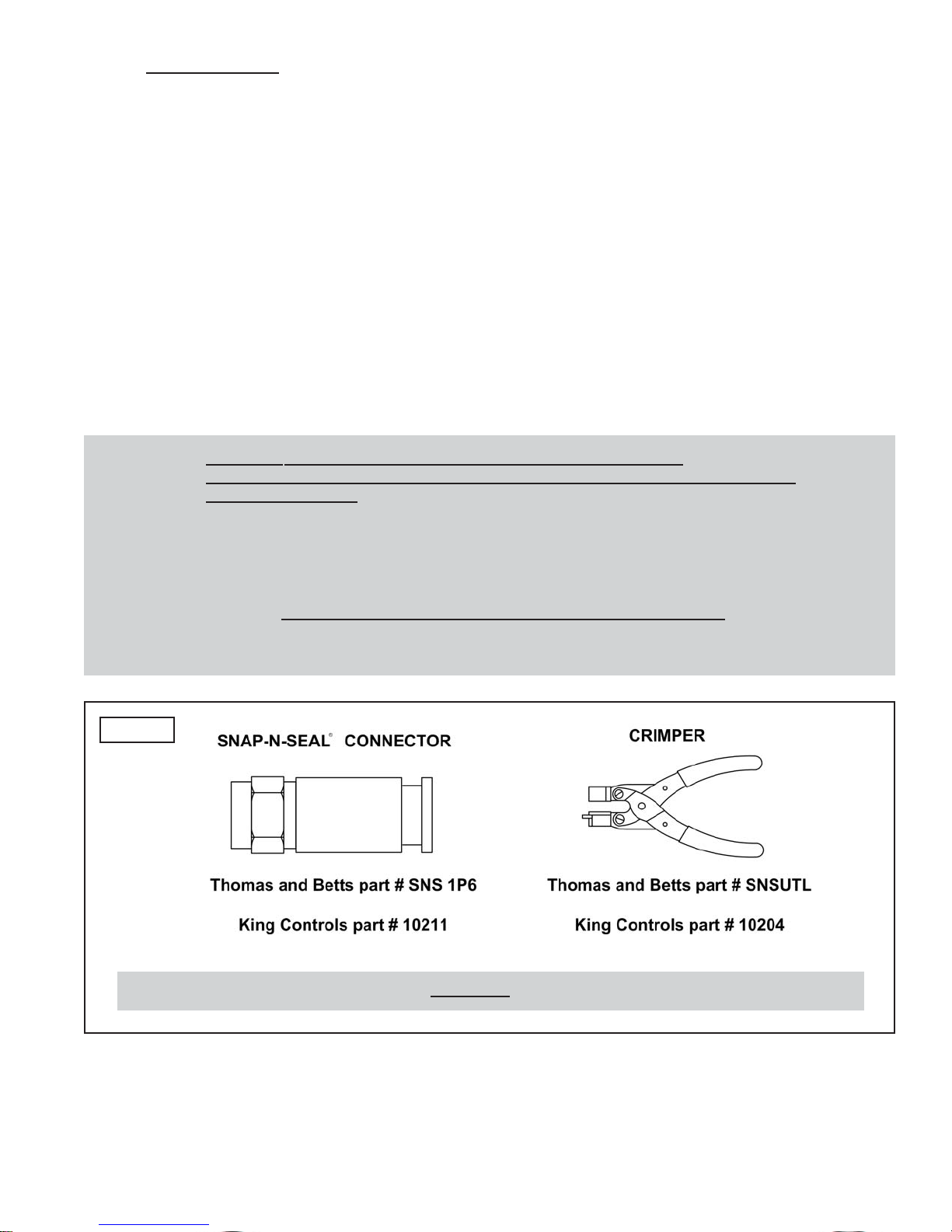
1) Ends must be terminated with SNAP-N-SEAL®connectors (Fig. 7.)
(DO NOT USE TWIST-ON OR HEX-CRIMPED CONNECTORS.)
2) Cable must be RG6 and rated at 2.2 GHz or higher.
IMPORTANT! Rubber O-rings must be REMOVED from ends of all SNAP-N-SEAL®connectors.
Page 10
IMPORTANT! Make sure power supply is disconnected from 110 volt source before continuing with
permanent installation.
The installer is responsible for weatherproofing all holes in the vessel.
Note: The installer is responsible for determining the most appropriate fastener to secure the dome unit to the
pedestal or vessel surface. Depending on the surface material, fasteners such as lag screws, sheet metal
screws, toggle bolts and T anchors may be used.
1. Determine the path of the coax cable(s) from the dome unit to the internal components.
Drill necessary holes (3/4”) in vessel surface where coax will enter vessel. Route coax
cable(s) leaving enough slack to attach to, and mount, dome unit.
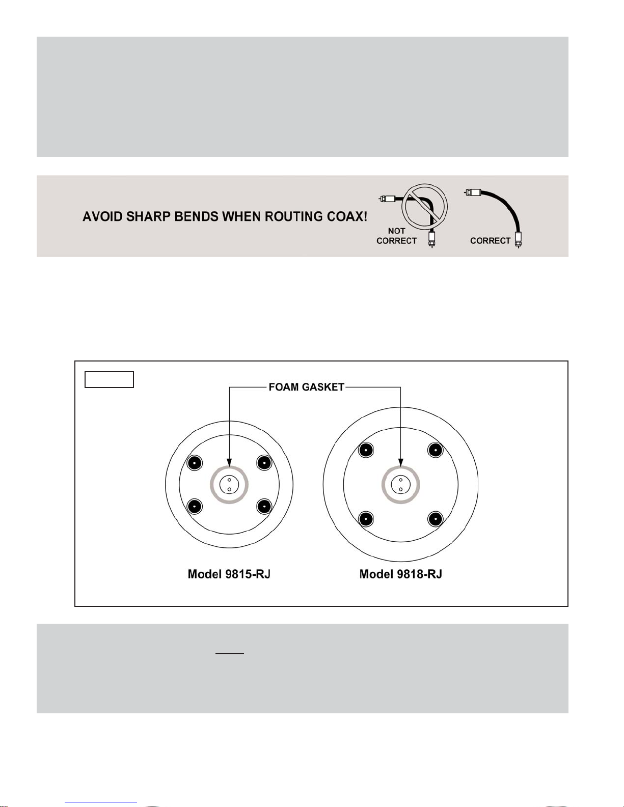
2. Apply foam gasket to bottom of dome unit (Fig. 8).
Note: The Sea-King is wired for multiple receiver support. There are two coax ports on the bottom of the dome
unit. The one labeled “MAIN” MUST be connected to the Tuner (IDB) in vessel. The unlabeled port can be
used for an additional receiver (see page 13).
IMPORTANT! You must fill the ends of all external coax cables with the supplied dielectric grease.
Failure to do so will void warranty.
Fig. 8
Page 11
5. Use the four mounting holes inside the base to install the dome unit to the mounting
pedestal or the vessel surface.
6. Secure coax every 12-18 inches and seal all openings where the coax enters the vessel
so they are entirely waterproof (inside and outside of the holes).
7. Replace dome cover on base and align holes in dome cover with holes in base. Attach
dome cover with dome cover screws saved earlier. Tighten ALL screws securely.
DO NOT APPLY ANY LOCKING COMPOUND TO THE SCREWS!
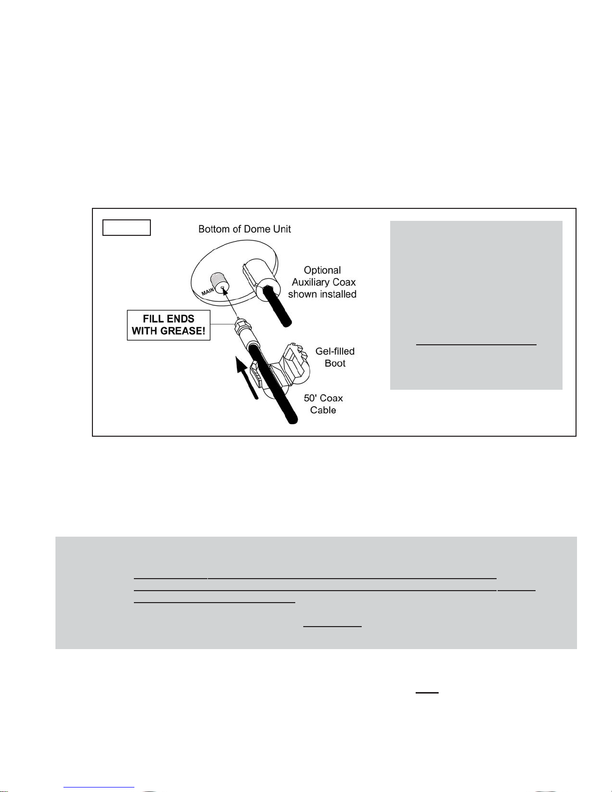
3. Fill end of coax cable that will connect to the MAIN port on the dome unit with supplied
dielectric grease. Connect this end of the coax cable to the MAIN port and tighten
connection (Fig. 9).
If using a second (auxiliary) receiver, fill end of second coax cable and connect it to the
unlabeled port. Tighten connection.
DO NOT OVER TIGHTEN CONNECTIONS.
4. Snap the gel-filled boots around the coax cables, then push flush against the bottom of
the dome unit.
IMPORTANT! The dome cover screws have a pre-applied locking compound on them.
DO NOT APPLY ANY ADDITIONAL LOCKING COMPOUND TO THE SCREWS.
APPLYING ADDITIONAL COMPOUND WILL VOID THE WARRANTY AND MAY CAUSE
CRACKING IN THE DOME COVER.
When re-installing the dome cover, CAREFULLYlower it onto the base, tilting it side to side
as necessary to prevent damaging internal components.
IMPORTANT!
You must fill the ends of the
external coax cables with the
supplied dielectric grease. Failure
to do so will void warranty.
Coax connections
should be snug.
DO NOT OVER TIGHTEN!
Gel-filled boots must sit flush
against bottom of dome unit.
Fig. 9

Page 12
INTERNAL WIRING
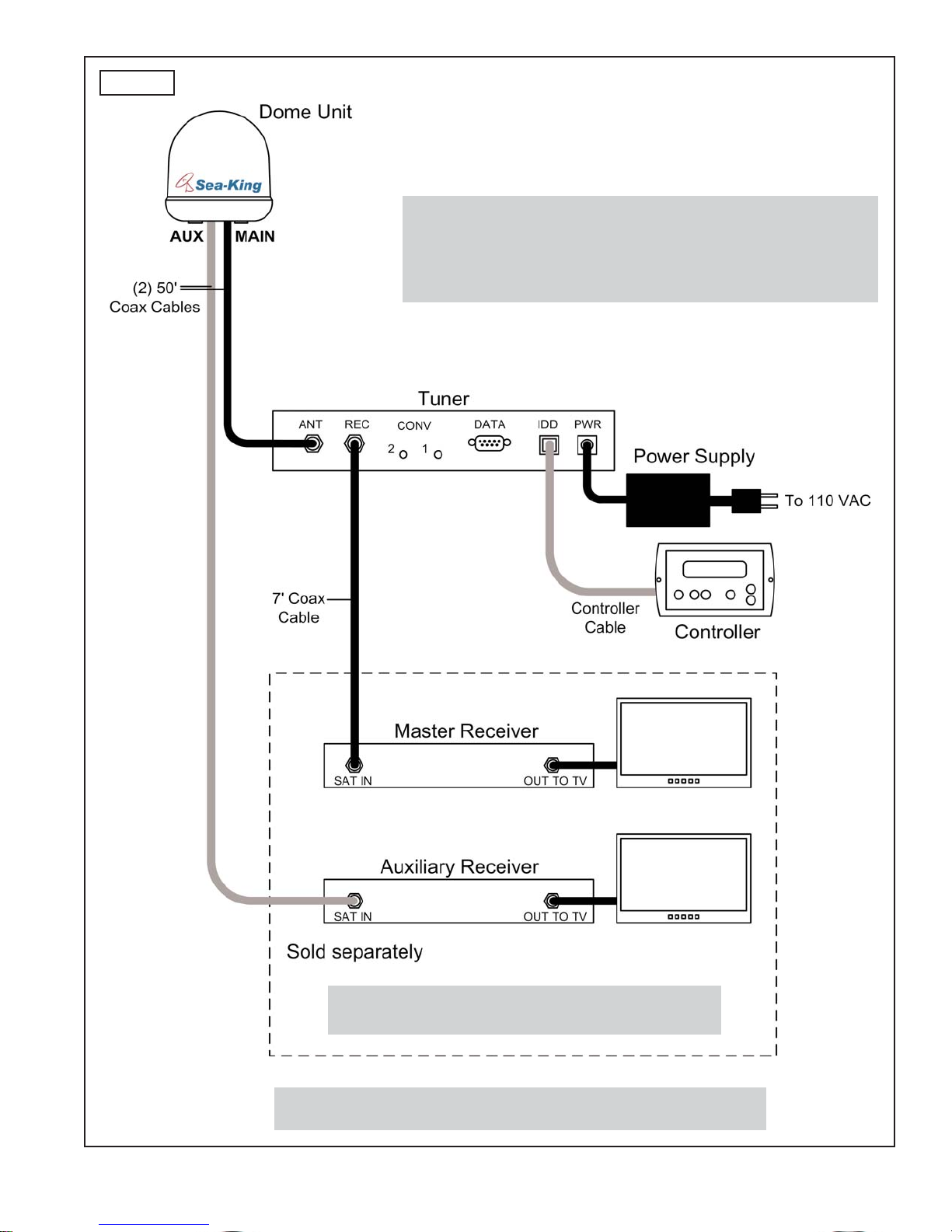
1. Make all connections as shown in the wiring schematic on page 13.
Apply a light coating of dielectric grease to the female threads of internal coax
connections and to the center stinger of the male coax connections.
ALWAYS CONNECT THE POWER SUPPLY LAST.
2. Perform a search to verify all connections are correct (see page 18).
Note: When the power supply is connected, the controller should turn on for 3 seconds and then turn off. If the
controller stays on, Press the ENTER and “-” buttons simultaneously to turn unit off.
IMPORTANT! The 50’ coax from the “MAIN” port on the dome unit MUST be connected to the Tuner (IDB)
in the vessel.
Coax connections should be snug. DO NOT OVER TIGHTEN!
CONNECT POWER SUPPLY LAST. When connecting the power supply cable to the tuner,
push in the power supply cable end until it is flush against the back of the tuner.
You must apply a light coating of dielectric grease to the female threads of internal coax
connections and to the center stinger of the male coax connections.
ELECTRICAL HAZARD WARNING!
The coax cable that connects the dome unit to the tuner carries a 24
volt electrical current. Exercise extreme caution when handling this
cable. Do not cut, break, or splice this line. Do not insert or connect
any devices such as splitters or any other device for any reason.
This line is not compatible with any other equipment. Damage will
occur to any device other than the dome unit if connected to the
antenna port on the tuner.
Page 13
Fig. 10
IMPORTANT! AVOID SHARP BENDS WHEN ROUTING COAX.
Note:
In order to view programming from the master and secondary
receivers simultaneously, both receivers must be tuned to a channel
broadcast from the same satellite. Use the controller to manually
switch satellites for the secondary receiver.
Note: HDTV receivers require HDMI or component
video/audio cable connection to TV.
Sea-King
Model 9815-RJ & Model 9818-RJ
Wiring Schematic

Page 14
MULTIPLE SATELLITE RECEIVER CONFIGURATIONS
With the use of an active multi-switch (sold separately by King Controls), more than two TV’s and
receivers can be hooked up (see Fig. 11 for typical 4 receiver hookup).
Diagram shows King Controls Multi-Switch #1810.
Other options:
3-4 satellite receivers: use one 2x4 or 3x4 active multi-switch
8 satellite receivers: use one 2x8 or 3x8 active multi-switch
16 satellite receivers: use one 3x16 active multi-switch
King Controls recommends the use of an active multi-switch.
Recommended brands (other brands may work as well):
Channel Master
Eagle Aspen
Perfect Vision
Spaun
Terk

Page 15
Fig. 11
IMPORTANT! AVOID SHARP BENDS WHEN ROUTING COAX.
IMPORTANT!
HDTV Converter must be connected to
18V input on multi-switch.
Sea-King
Model 9815-RJ & Model 9818-RJ
Typical 4 Receiver Hookup

Page 16
The Faceplate is optional and can be removed as follows (Fig. 13):
1. Remove 4 screws from Controller.
2. Slide Faceplate off of Controller.
3. Replace 4 screws.
OPTIONAL WALL MOUNT FACEPLATE (INCLUDED)
1. Use the Faceplate as a template to mark and cut out the mounting cavity, and if
necessary, mark and drill the mounting holes (Fig. 12).
2. Mount Faceplate in wall with supplied screws.
Fig. 13
Note:
Depending on the mounting
surface, pilot holes for the
screws may or may not need
to be drilled.
Fig. 12
Note: If not using the faceplate, see faceplate removal instructions below.
IMPORTANT! Depending on the thickness of the vessel wall, a relief notch may need to be cut for the
cable. THE CABLE MUST NOT BE PINCHED OR BENT WHEN MOUNTING THE DISPLAY.

Page 17
TUNER MOUNTING OPTIONS
You can mount the tuner or leave it freestanding:
a) You can mount the tuner to an appropriate surface (Fig. 14).
b) You can leave the tuner freestanding. If space requirements dictate, the mounting feet
can be snapped off.
Fig. 14
Note: The installer is responsible for determining the most appropriate fasteners to secure
the tuner to the chosen surface.
Depending on the mounting surface, pilot holes for the fasteners may or may not
need to be drilled.
Page 18
IMPORTANT! There must be a clear “line of sight” to the satellite (See Fig. 2, Page 3). Terrain, other
boats, buildings, trees, masts, telephone poles, etc. can all block the satellite signal from
reaching the dish.
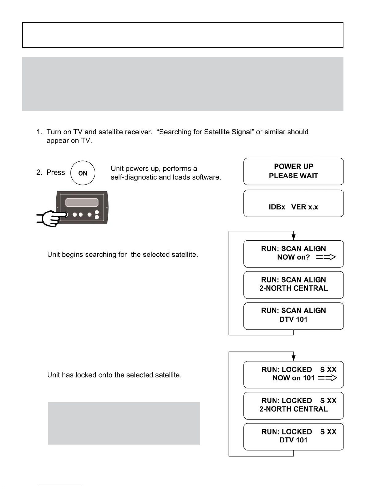
Note: This example is for the DTV 101 satellite in Region 2-North Central. The information on your controller will
vary depending on the satellite and region you have chosen (see pages 20-21).
SECTION 4 OPERATION
Note: The Sea-King must remain powered on to
maintain a signal. If you are going to be
stationary and wish to continue watching TV,
DO NOT TURN THE SYSTEM OFF.
This manual suits for next models
1
Table of contents
Other Sea King Receiver manuals

Popular Receiver manuals by other brands

Intermatic
Intermatic RC613R Installation, operation & service manual

Integra
Integra DTR-40.6 Advanced manual

American Dynamics
American Dynamics AD1686B Specifications

Panasonic
Panasonic SC-HT270 Operating operating instructions

JVC
JVC RX-DV3SL Service manual

steute
steute RF R T SW2.4 Series Mounting and wiring instructions


