Atlona AT-HDR-EX-70C-KIT User manual

1
Installation Guide
AT-HDR-EX-70C-KIT
4K HDR HDMI Over HDBaseT TX/RX Kit
AT-HDR-EX-70C-KIT
The Atlona AT-HDR-EX-70C-KIT is an HDBaseT transmitter/receiver kit for high dynamic range
(HDR) formats. The kit is HDCP 2.2 compliant and supports 4K/UHD video @ 60 Hz with 4:4:4
chroma sampling, as well as HDMI data rates up to 18 Gbps. The HDR-EX-70C-KIT provides
transmission of HDMI, as well as bidirectional IR and RS-232 control signals up to 230 feet
(70 meters) for 1080p video, and up to 130 feet (40 meters) for 4K HDR over CAT6a/7 cable.
This extender kit features visually lossless compression with no latency to enable HDR and
4K/60 4:4:4 video signal extension over HDBaseT. For additional integration convenience, the
transmitter remotely powers the receiver through Power over Ethernet (PoE). The HDR-EX-70C-
KIT delivers a cost-eective solution for HDMI and control signal extension, and includes surface
mounting hardware for discrete installation.
IMPORTANT: Visit http://www.atlona.com/product/AT-HDR-EX-70C-KIT for the latest
rmware updates and Installation Guide.
1 x AT-HDR-EX-70C-TX
1 x AT-HDR-EX-70C-RX
4 x Mounting brackets
8 x Mounting screws
1 x 48V DC power supply
1 x IR emitter
1 x 2-pin captive screw connector
2 x 3-pin captive screw connector
1 x 4-pin captive screw connector
1 x 5-pin captive screw connector
1 x Installation Guide
Package Contents

2
Installation Guide
AT-HDR-EX-70C-KIT
AT-HDR-EX-70C-RX
POWER
LINKFW
RS-232
RX TX SS
P
HDBaseT IN HDMI OUT
IR OUT
IR IN
DC 48V
-
+
RS-232
RX TX SS
HDBaseT OUT HDMI IN
IR OUTIR IN
AT-HDR-EX-70C-TX
POWER
LINKTEST UTILITY
1. LINK
2. FW
3. TEST
4. 5V LOCK
Panel Descriptions
1 TEST
Quick and easy test for cables. Use the
button to start the test and the LED to
determine pass or fail.
2 UTILITY
Connect a mini-USB to USB-A cable from
this port to a computer for updating and
testing. Rotate the dial to set the unit into
dierent modes.
3 POWER and LINK LEDs
The power LED will illuminate green when
receiving power. The link LED will glow
yellow when signal is being sent/received
between the transmitter and the receiver.
4 DC 48V
Connect the included power supply to this
port.
5 RS-232
Bidirectional control port, used for pass
through of commands to or from the
receiver.
6 IR
Connect a 3rd party controller to the IR IN
port or an IR emitter to the IR OUT port.
7 HDBaseT OUT
Connect an HDBaseT cable from this port
to the HDBaseT IN port on the receiver.
8 HDMI IN
Connect an HDMI cable from a source to
this port. e.g. HDR BluRay Player
9 FW
Connect a mini-USB to USB-A type cable
from this port to a computer, to update
the rmware.
10 POWER and LINK LEDs
The power LED will illuminate green when
receiving power. The link LED will glow
yellow when signal is being sent/received
between the transmitter and the receiver.
11 RS-232
Bidirectional control port, used for pass
through of commands to or from the
receiver.
12 IR
Connect an IR receiver to the IR IN port or
an IR emitter to the IR OUT port.
13 HDBaseT IN
Connect an HDBaseT cable from this
port to the HDBaseT OUT port on the
transmitter.
14 HDMI OUT
Connect an HDMI cable from this port to
an HDMI display.
11
5 6 7 8 12 14
13
4
10
39
21

3
Installation Guide
AT-HDR-EX-70C-KIT
Pin out will be determined by the
RS-232 cable and connect as
RX (receive), TX (transmit) and
(Ground).
A 3-pin captive screw connector for RS-232 has been included.
Two captive screw connectors for IR have been included. A 4-pin connector for the transmitter
and a 3-pin connector for the receiver.
IR IN is connected by a power, ground, and signal
wire. Use a 12V IR receiver with it (e.g. AT-IR-CS-RX
purchasable through atlona.com).
IR IN is connected by a ground and signal wire. Use
with 3rd party control systems. For easy termination,
Atlona recommends using the 2 meter IR cable AT-LC-
CS-IR-2M (purchasable through atlona.com).
IR OUT is connected by a ground and signal wire.
Use the included IR emitter with this port.
IR OUT is connected by a ground and signal wire.
Use the included IR emitter with this port.
RS-232
IR
IR IN IR OUT
GND S
S
P
GND RX TX
GNDRX TX
IR IN IR OUT
GND S
S
The AT-HDR-EX-70C-KIT includes two mounting brackets and four mounting screws each, which
can be used to attach the units to any at surface.
1. Position one of the mounting brackets,
as shown below, aligning the holes on
the side of the enclosure with one set of
holes on the mounting bracket.
2. Use the enclosure screws to secure the
mounting bracket to the enclosure.
3. Repeat the above steps to attach
the second mounting bracket to the
opposite side of the unit.
Mounting Instructions
FW
AT-HDR-EX-70C-RX
POWER
LINK
Included screws

4
Installation Guide
AT-HDR-EX-70C-KIT
4. Mount the unit using the oval-shaped holes, on each mounting bracket. If using a drywall
surface, a #6 drywall screw is recommended.
NOTE: Mounting brackets can also be inverted
to mount the unit under a table or other at
surface.
FW
AT-HDR-EX-70C-RX
POWER
LINK
1. Connect an HDR source to the HDMI IN port on the transmitter.
2. Connect an HDR display to the HDMI OUT port on the receiver.
3. Connect an HDBaseT cable, from the HDBaseT OUT port on the transmitter, to the
HDBaseT IN port on the receiver.
4. *Optional* Connect a 3rd party controller to the transmitter using either the 3-pin RS-232
or the 2-pin IR IN ports.
5. *Optional* Connect an IR receiver to the IR IN port of the receiver.
6. *Optional* Connect an IR emitter to the IR OUT port of the transmitter or receiver.
7. Connect the included 48V power supply into the transmitter.
8. Connect power supply to an AC outlet.
Installation
Refer to the tables below for recommended cabling when using Altona products with HDBaseT.
The green bars indicate the signal quality when using each type of cable. Higher-quality signals
are represented by more bars.
Cable Recommendation Guidelines
Core Shielding CAT5e CAT6 CAT6a CAT7
Solid UTP (unshielded) N/A
STP (shielded)
Performance Rating (MHz) 350 500 600 800
*Atlona recommends TIA/EIA 568-B termination for optimal performance.
Cable* Max. Distance @ 4K Max. Distance @ 1080p
CAT5e / CAT6 115 feet (35 meters) 200 feet (60 meters)
CAT6a / CAT7 130 feet (40 meters) 230 feet (70 meters)
IMPORTANT: Stranded or patch cables are not recommended due to performance
issues.

5
Installation Guide
AT-HDR-EX-70C-KIT
Connection Diagram
DC5V HDBaseTIN HDMIOUT
Video
Video
Video
Control
Control
AT-HDR-EX-70C-TX
AT-HDR-EX-70C-RX
AT-JUNO-451
Automation Control System
1 2 3 4
HDMI IN HDMI OUT OPTICAL
AT-JUNO-451
RS-232 IR IN LAN DC 5V
TX S
RX
Video
HDBaseT
Video
Set-Top Box
HDR Blu-ray Player
Media player
4
media4
SET-TOPBOX
OK
224
2
COM
NC
NO
COM
NC
NO
COM
NC
NO
COM
NC
NO
+12V
SIG
GND
+12V
SIG
GND
+12V
SIG
GND
+12V
SIG
GND
1
COMPONENT
HDMI
1
2
3
4
5
6
SERIAL1
IROUT SERIAL2
L
R
DIGITAL
COAXOUT
AUDIOOUT AUDIOIN ETHERNET
2 3 4
VIDEOOUT
48VDC
FACTORY
RESET
DC 48V
-
+
RS-232
RX TX SS
HDBaseT OUT HDMI IN
IR OUT
IR IN
AT-HDR-EX-70C-TX
POWER
LINKTEST UTILITY
1. LINK
2. FW
3. TEST
4. 5V LOCK
HDR UHD/HD Display
AT-HDR-EX-70C-RX
POWER
LINKFW
RS-232
RX TX SS
P
HDBaseT OUT HDMI IN
IR OUT
IR IN
TEST
The HDR-EX-70C-TX has the ability to test the HDBaseT cable quality through the front panel.
Press the test button on the front panel of the transmitter to start the test.
Button:
• Blue Blinking: The test is running properly.
• Red Light: There is no signal for the test to check.
LED:
• No Light: There is no HDBaseT cable plugged in.
• Blinking: There is no HDBaseT signal coming through.
• Green: The HDBaseT cable is good.
• Yellow: One or two HDBaseT pairs are not working, reterminate
the cable.
• Red: Multiple pairs are not working. Reterminate the cable and if
the LED turns yellow or red again, replace the cable.
DC 48V
-
+
RS-232
RX TX SS
HDBaseT OUT HDMI IN
IR OUTIR IN
AT-HDR-EX-70C-TX
POWER
LINK
TEST
UTILITY
1. LINK
2. FW
3. TEST
4. 5V LOCK

6
Installation Guide
AT-HDR-EX-70C-KIT
Mode 1: Link
This is the default position of the dial and puts the unit into normal operation.
Mode 2: FW
This mode sets the transmitter into rmware updating mode. View Firmware Updating
instructions on the next page for manual updating.
1. Open the Analyzer software.
2. Plug in the power supply of the transmitter.
3. Connect the receiver using an HDBaseT cable.
4. Connect an active source to the transmitter and an active display to the receiver. Set the
source to the highest resolution.
5. Set the Utility dial to 3.
6. Connect the transmitter’s Utility mini USB port to a PC using a mini USB to USB A cable.
7. Select the COM port in the Analyzer software and press the connect button.
8. Once connected, press the Start button. The link information and cable pairing test
results will display. Follow the instructions on the Analyzer software for any pair failures.
9. When complete, set the utility dial back to 1or 4for normal operation.
Mode 3: TEST
This mode sets the transmitter into HDBaseT testing and debugging mode. Firmware may also
be updated in this mode using the Atlona Analyzer software.
DC 48V
-
+
RS-232
RX TX SS
HDBaseT OUT HDMI IN
IR OUTIR IN
AT-HDR-EX-70C-TX
POWER
LINKTEST
UTILITY
1. LINK
2. FW
3. TEST
4. 5V LOCK
UTILITY
The utility port and dial are used for updating rmware,
HDBaseT cable testing/debugging, and 5V lock. Use the Dial
to switch between modes.
NOTE: Before setting the unit to mode 3 (TEST), the Atlona Analyzer should be
downloaded from the resource tab located at
http://www.atlona.com/products/AT-HDR-EX-70C-KIT
Quality Testing
Firmware Updating (Analyzer software only)
1. Download the rmware le from the rmware tab located at http://www.atlona.com/AT-
HDR-EX-70C-KIT.
2. Set the dial to 3.
3. Open the Analyzer software.
4. Connect the transmitter’s Utility mini USB port to a PC using a mini USB to USB A cable.
5. Select the COM port and press the connect button.
6. Select Update from the top navigation.
7. Press the Browse button and a new window will open.
8. Select the rmware le for the transmitter and press open.
9. Press the Load button. The progress bar will display the update progress.
10. Once the update is complete, set the dial back to 1 or 4 to return to normal operation.

7
Installation Guide
AT-HDR-EX-70C-KIT
1. Open the Analyzer software.
2. Select Debug from the top navigation.
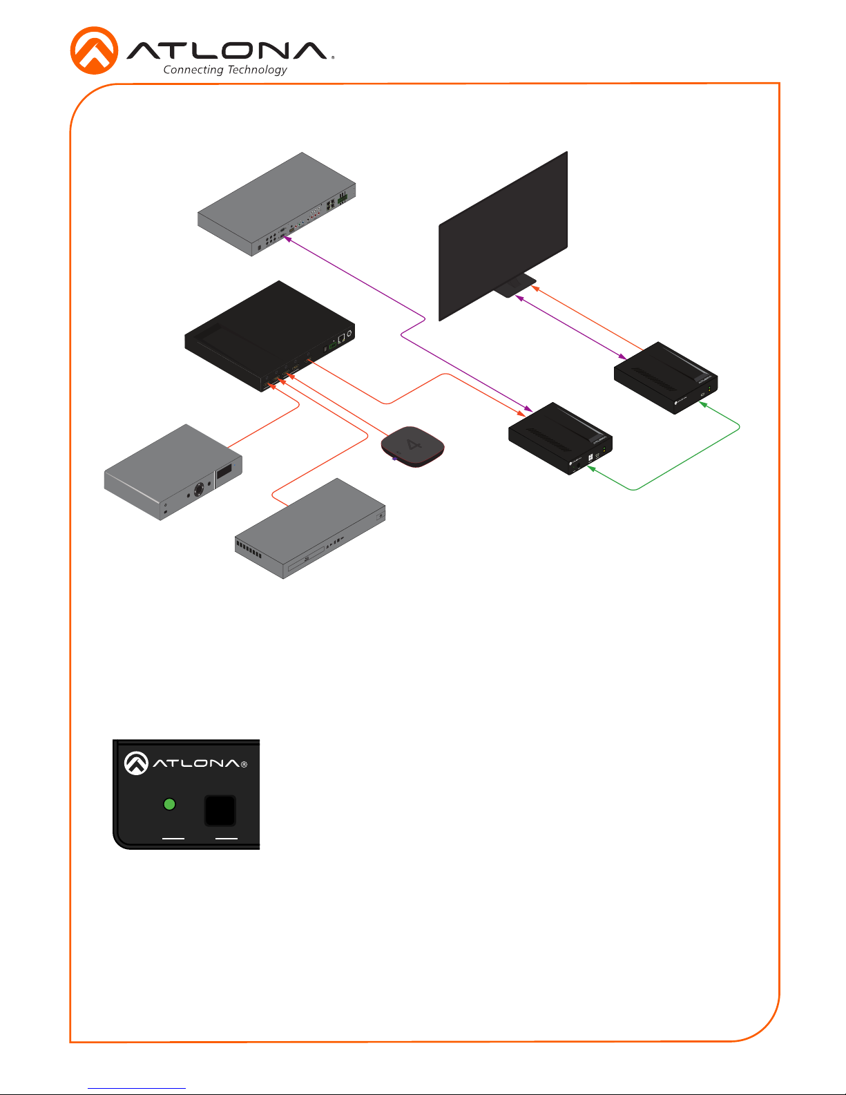
3. Plug in the power supply of the transmitter.
4. Connect the receiver using an HDBaseT cable.
5. Connect an active source to the transmitter and an
active display to the receiver. Set the source to the
highest resolution
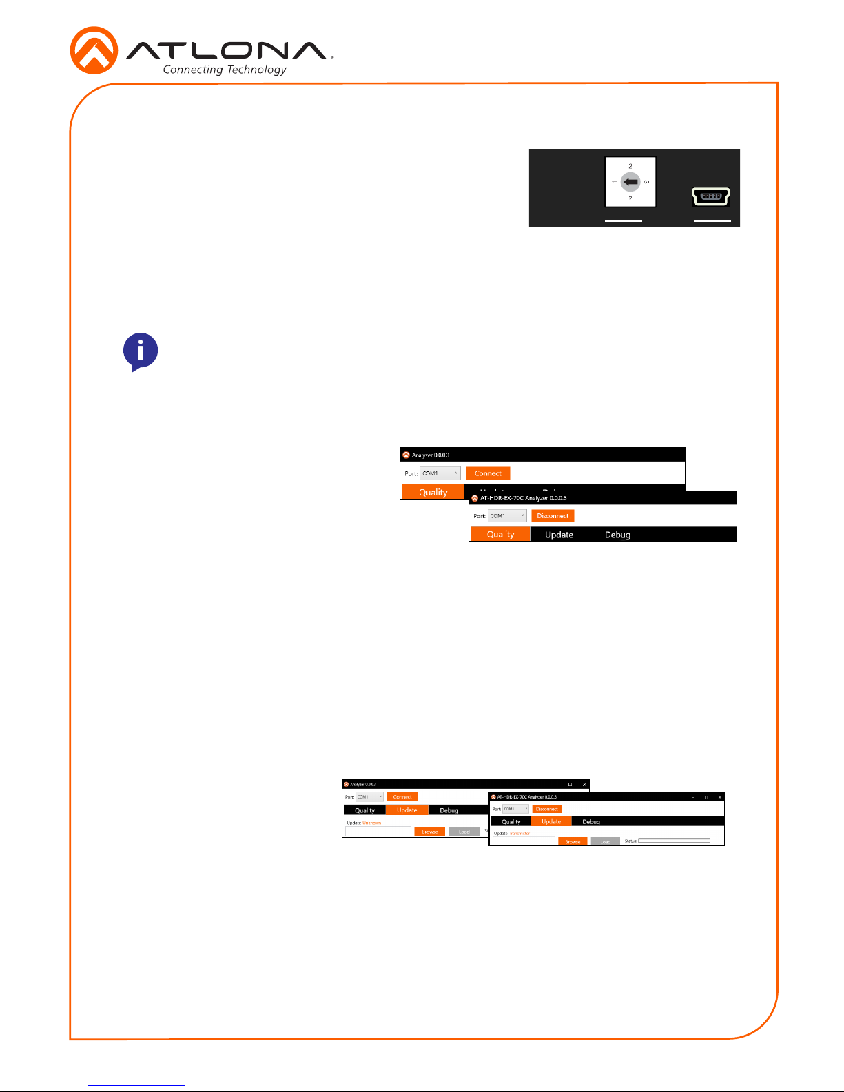
6. Set the Utility dial to 3.
7. Connect the transmitter’s Utility mini USB port to a PC
using a mini USB to USB A cable.
8. Select the COM port and press the connect button.
9. Press the Debug button. Information will appear in the box eld if there is any data that
can be logged. The log can be saved to the local computer if needed.
10. Set the dial back to 1 or 4 for normal operation.
Debug
Mode 4: 5V Lock
This mode sets the +5V and the HPD signal of the transmitter and receiver to high. This allows
the source and display to have a consistent connection, even if there are issues with the source
and display signals.
Updating Firmware (manually)
1. Download the rmware .zip le from the rmware tab located at http://www.atlona.com/AT-
HDR-EX-70C-KIT.
2. Extract the rmware, from the archive le, to the Windows desktop or other folder.
3. Make sure the included 48 V DC power supply is connected to the transmitter and that an
Ethernet cable is connected between the HDBaseT OUT and HDBaseT IN ports on the
transmitter and receiver, respectively.
Transmitter only:
a. Set the UTILITY dial to 2.
b. Disconnect the 48 V DC power supply from the transmitter.
c. Connect a mini-USB to USB-A cable from the UTILITY port, on the transmitter, to the
computer with the rmware le.
d. Reconnect the power supply to the transmitter. The USB Drive folder should be
displayed after a few seconds. If the folder is not displayed select the USB drive from
Windows Explorer.
e. Go to step 4.
The following procedure covers manually updating the rmware. This method will be required
if not using the Atlona Analyzer. If using the Atlona Analyzer, refer to Firmware Updating
(Analyzer software only), on page 6.

8
Installation Guide
AT-HDR-EX-70C-KIT
© 2018 Atlona Inc. All rights reserved. “Atlona” and the Atlona logo are registered trademarks of Atlona Inc. All other brand names and trademarks or registered
trademarks are the property of their respective owners. Pricing, specications and availability subject to change without notice. Actual products, product images, and
online product images may vary from images shown here.
Version 2
atlona.com •408.962.0515 •877.536.3976
Receiver only:
a. Disconnect the Ethernet cable from the HDBaseT IN port on the receiver.
b. Connect a mini-USB to USB-A cable from the FW port on the receiver, to the computer
with the rmware le.
c. Reconnect the Ethernet cable to the HDBaseT IN port on the receiver. The USB Drive
folder should be displayed after a few seconds. If the folder is not displayed select the
USB drive from Windows Explorer.
d. Go to step 4.
4. Delete all les from the USB Drive folder, if any are present.
5. Drag and drop the rmware le to the drive. While the rmware loads to the unit, the green
power LED on the front panel will ash.
6. Once the LED is solid green, disconnect the unit from the computer.
Transmitter only:
f. Set the UTILITY dial to 1to resume normal operation.
7. The rmware update process is complete.
Table of contents
Other Atlona Receiver manuals

Atlona
Atlona AT-RGB45SR User manual

Atlona
Atlona AT-HDR-EX-70-2PS User manual

Atlona
Atlona AT-HDWP-UK User manual

Atlona
Atlona AT-UHD-EX-100CE-RX-PSE User manual

Atlona
Atlona AT-LinkCastAV User manual

Atlona
Atlona AT-HDRX-RSNET User manual

Atlona
Atlona AT-HDWP User manual

Atlona
Atlona AT-HDMI40SRS User manual

Atlona
Atlona AT-HD50SS User manual

Atlona
Atlona AT-HD15SRS User manual
Popular Receiver manuals by other brands

BRB Systems USA
BRB Systems USA TX-101 instruction manual

Johnson Controls
Johnson Controls Tyco HSM2HOST installation guide

Pioneer
Pioneer VSX-1021-K quick start guide

DoorKing
DoorKing 8054 MicroPlus Installation and programming instructions

AMX
AMX Endeleo UDM-RX01 quick start guide

ELAD
ELAD FDM77 operating manual