Integra LifeSciences MAYFIELD A1115 User manual

EN –ENGLISH...............................................................................
FR –FRANÇAIS..............................................................................
IT –ITALIANO................................................................................
DE –DEUTSCH .............................................................................
ES –ESPAÑOL...............................................................................
NL –NEDERLANDS......................................................................
MAYFIELD®
Modified
Swivel Adaptor
( A1115)
Instruction Manual
Manufacturer:
Integra LifeSciences Corporation
4900 Charlemar Drive, Building A
Cincinnati, OH 45227, USA
Tel: 513-533-7979
Fax: 513-271-1915
integralife.com
Integra LifeSciences Services
Immeuble Séquoïa 2
97 allée Alexandre Borodine
Parc Technologique de la Porte des Alpes
69800 Saint Priest – France
Tel: 33 (0) 4 37 47 59 10

2
This page is intentionally le blank

3
2
MAYFIELD®
Modified
Swivel Adaptor
( A1115)
Instruction Manual
EN – ENGLISH
4
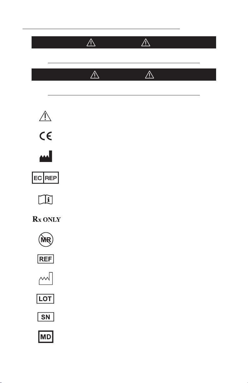
Meaning Of Symbols Used In This Manual - ENGLISH
CAUTION!
Hazards which could result in equipment or property damage
WARNING!
Hazards which could result in severe personal injury or death
Caution
Product complies with the requirements of MDR 2017/745
Manufacturer
Authorized Representative in the European Community
Consult Instructions for Use
Caution: Federal (USA) law restricts this device to sale by or on the
order of a licensed healthcare practitioner.
This device is not indicated for use in the MR environment
Catalog number
Date of manufacture (YYYY-MM-DD)
Lot number
Serial number
Medical Device

5
ENGLISH
Description
The MAYFIELD® Modified Swivel Adaptor (REF A-1115) is designed to provide all the
functionality of the standard swivel adaptor, and in addition offers a feature to tighten the
fit of the ratchet extension to the body of the skull clamp, when the adaptor is used with a
skull clamp. The tightened fit of the ratchet extension reduces motion that might be caused
by the tolerance differences of these two components, thereby minimizing movement of
the skull clamp during a surgical procedure. (In procedures such as image-guided surgery, or
procedures under a microscope, minimal or no movement of the skull clamp is desired.)
Section 1
1
2
3
4
5
6
7
8
Illustration 1
1. Torque Screw
2. Small Starburst
3. Swivel Sleeve
4. Swivel Base
5. Torque Screw with Pin
6. Adjustment screw
7. Large Starburst
8. Pin
Indications for Use/Intended Purpose
The MAYFIELD Modified Swivel Adaptor aaches to the MAYFIELD Base Unit to support
skull clamps and headrests (A-1011, A-1051, A-1012, A-1059, A-1108, and A-2000). It provides
optimal positional flexibility via 360-degree rotation as well as supplementary stability of
the skull clamp ratchet extension.
WARNING:
This device is not intended for use in or near the vicinity of a strong magnetic field.
(MRI)
WARNING:
Failure to properly position patient and to fully tighten and secure all adjustable
portions of this or any similar device may result in skull pin slippage and serious
patient injury, such as scalp laceration, skull fracture, or even death.
6
EN – ENGLISH
WARNING:
Do not alter the design of the device in part or whole as serious patient injury could
result.
WARNING:
Failure to read and follow instructions furnished in this product insert may result in
skull pin slippage and serious patient injury, such as scalp lacerations, skull fracture,
or even death.
Make certain to securely aach the base unit to the operating room table.
WARNING:
If the Modified Swivel Adaptor Torque Screw becomes tight before the starburst
is properly meshed, the knob is incorrectly adjusted for this skull clamp. Use a
5/64” hex wrench to turn the adjustment screw counter clockwise four full turns to reset
the screw. See Illustration 1 for adjustment screw location. If the starburst fails to mesh
correctly aer the screw is reset, the Modified Swivel Adaptor may be incompatible with
this particular clamp. See Section 2 for details.
WARNING:
The Modified Swivel Adaptor may be incompatible with earlier skull clamps made
with a two piece base design. See Section 2 to recognize incompatible conditions.
Intended Population
MAYFIELD Skull Clamp fixation devices are not recommended for use on children under five (5) years of
age. Extreme caution should be exercised in pediatric cases because of the thin skull.
Inspection
Always inspect instruments before and aer use. If a component appears damaged and/
or does not seem to function properly, do not use the device and immediately send the
instrument to an authorized Integra repair center for evaluation, repair or replacement.
Allow your Integra Representative to inspect this device a minimum of two times per year to
assist you in its proper function.
Adjustment
Before its first use, the Modified Swivel Adaptor should be adjusted to ensure optimal
performance with your specific skull clamp.
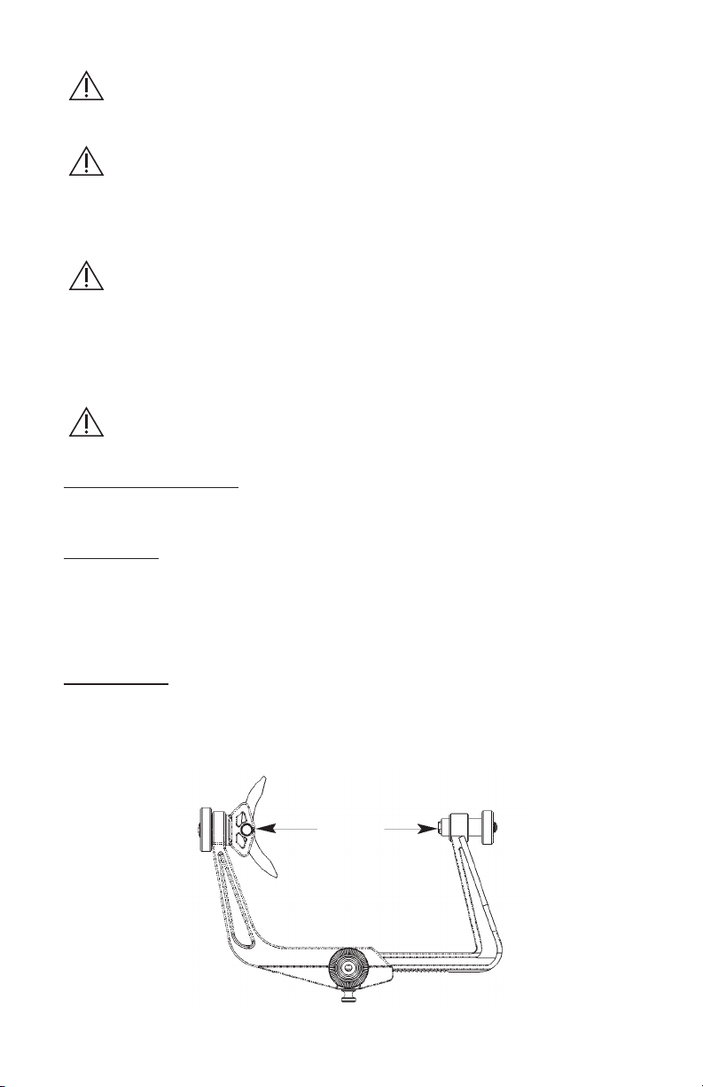
1. Obtain the skull clamp with which the swivel adaptor will be used and position the
ratchet extension to approximately half its travel. See Illustration 2:
7-8"
Illustration 2
7
EN – ENGLISH
2. Apply the Modified Swivel Adaptor to the skull clamp and carefully inspect the starburst
connection to see that it is properly meshed and secure. See Illustration 3.
Good starburst
connection
Clamp/Swivel
movement from
incomplete
starburst mesh
Incorrect
Correct
Illustration 3
WARNING:
If the Modified Swivel Adaptor Torque Screw becomes tight before the starburst is
properly meshed, the knob is incorrectly adjusted for this skull clamp. Use a 5/64”
hex wrench to turn the adjustment screw counter clockwise four full turns to reset the
screw. See Illustration 1 for adjustment screw location.
If the starburst fails to mesh correctly aer the screw is reset, the Modified Swivel Adaptor
may be incompatible with this particular clamp. See Section 2 for details.
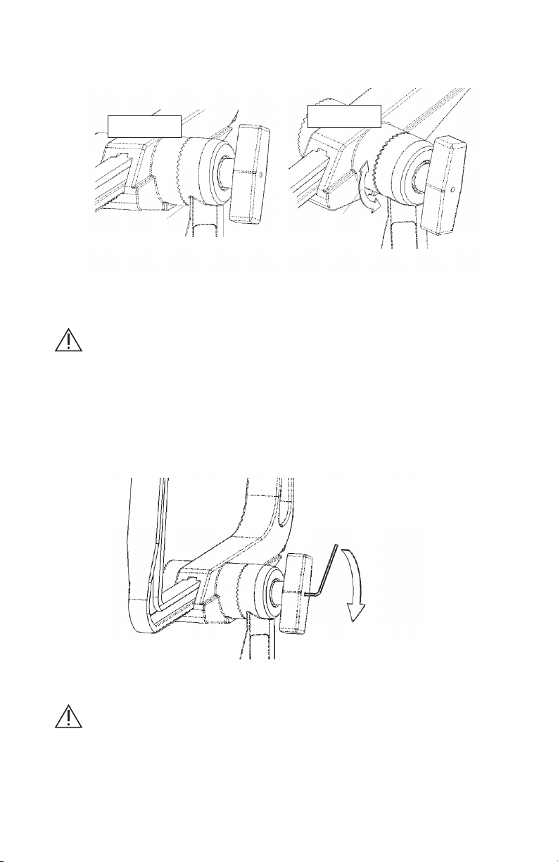
3. With the adapter securely applied to the skull clamp, use a 5/64” hex wrench to turn
the adjustment screw clockwise until it is tight. See Illustration 4. Check the ratchet
extension for movement.
Use 5/64" hex wrench
Illustration 4
WARNING:
This seing is optimized for use on that skull clamp to which it is adjusted. A single
seing may be effective on several skull clamps but it may also be over-adjusted for
some other clamps.
During the preoperative equipment check, verify that the starburst teeth fully engage
on the skull clamp that will be used. It is important for patient safety to perform this
inspection before the equipment is used for patient support.

8
EN – ENGLISH
Instructions for Use
1. Mount the Base Unit with the Transitional Member onto the operating table.
2. Aach the Modified Swivel Adaptor to the Transitional Member of the Base Unit by
inserting the adaptor’s small starburst torque screw into the threaded hole on the
transitional member as shown in Illustration 5:
Turn torque screw clockwise
to secure. Inspect starburst
teeth to confirm correct
engagement.
Illustration 5
CAUTION:
Always confirm the starburst teeth mesh properly (as shown in Illustration 3) Failure
to do so may result in damage to the device
3. Mount the headrest or skull clamp on the swivel adapter by inserting the large starburst
Torque Screw into the threaded hole in the skull clamp or headrest. See Illustration 6:
Turn torque
screw clockwise
to secure.
Inspect starburst
teeth to confirm
correct engagement.
Illustration 6
4. The position of the headrest may be adjusted at the swivel adapter and the base unit to
improve patient comfort or accomodate the surgeon’s preference.
CAUTION:
Stabilize the patient’s head or the headrest equipment until all the connections are
secured against movement.

9
EN – ENGLISH
To change the position at the swivel adapter, loosen the appropriate Torque Screw by
turning the screw counter clockwise two full turns to assure clearance for the starburst
teeth.
Once the desired position is achieved, lock the joint by turning the torque screw clockwise.
Verify that the starburst teeth are correctly engaged at both locations and that the torque
screws are fully tightened.
IMPORTANT:
A correctly adjusted modified swivel adapter will behave as a lock knob in securing
the ratchet extension against movement.
RELEASE
PROCEDURE
2. PULL PLUNGER
1. UNLOCK
SWIVEL ADAPTER
Illustration 7
The Torque Screw at the large starburst connection must be loosened (typically two full
turns) before pulling the plunger on the skull clamp will release the ratchet extension.
Section 2
Recognizing Incompatible Equipment
Older model skull clamps fabricated using the two-piece, machined race lock in the body
of the skull clamp will not accept the extended stud that is part of the Modified Swivel
Adaptor. Access to the ratchet arm is partially obstructed, causing the Modified Swivel
Adaptor Torque Screw to stop before the starbursts can properly engage. Compatibility can
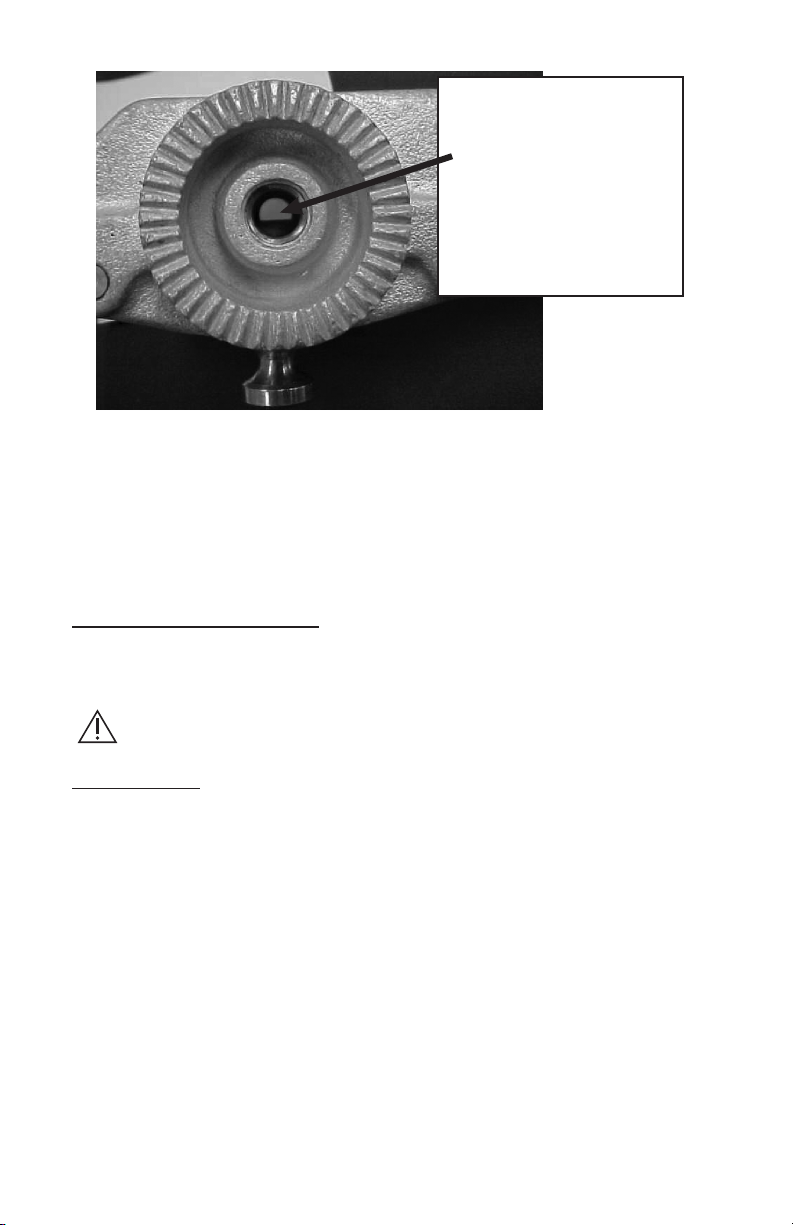
be readily determined by looking through the threaded hole on the skull clamp base.
Look for a
two piece
base design,
indicated by
the fasteners.
10
EN – ENGLISH
A close inspection of
the hole will reveal the
obstruction that
prevents the Modified
Swivel Adaptor from
operating with this
clamp.
It is possible to convert some of these older model clamps to accept the longer post of the
Modified Swivel Adaptor. Evaluations on suitability for conversion are made by the Service
Department.
Phone: 877-444-1114 (USA only) or (513) 533-7979
Integra LifeSciences Corporation
4900 Charlemar Drive, Building A
Cincinnati, Ohio 45227
Cleaning and Sterilization
The Modified Swivel Adaptor should be thoroughly cleaned aer each use. Scrub with a
so brush and use pH-neutral detergent. Clean thoroughly to prevent traces of blood or
debris from interfering with movement. Wipe down with an antiseptic solution
DO NOT STEAM STERILIZE!
Plastic components may be damaged by the heat.
Manual Wash
CAUTIONS
• Alkaline and highly acidic detergents and solutions cause damage to the devices.
• Channels and crevices found on this device require particular aention during cleaning.
• Pay special aention to the water quality used throughout reprocessing. Hard water can
damage the surface of the equipment. Avoid using hard water. Instead use purified water
unless otherwise specified.
Limitations on reprocessing
• Repeated processing has minimal effects on these devices. Product life is normally
determined by wear and damage due to use.
• It is important to have Integra NeuroSpecialists perform routine inspections (twice yearly
is recommended). See contact information below.
INSTRUCTIONS
Containment/Transportation
• Follow health care facility protocol for safe containment and transport to the
decontamination environment.
• It is recommended that devices are cleaned immediately aer use.

11
EN – ENGLISH
Preparation for Cleaning
• Disassembly is required.
Disassembling Equipment Inspecting for Cleanliness
Completely remove the swivel adaptor
from any components. The swivel adaptor
itself cannot be disassembled any further.
Inspect the teeth of the starbursts, the area
around the locking screw, and the base of
the swivel adaptor for organic debris.
Cleaning – Manual Equipment: Water, Neutral pH Detergent, So Bristle Brush, Towels
Method
1. Prepare neutral pH enzymatic detergent solution (e.g. Endozime® AW Triple Plus with APA
(Ruhof), 1:128 ratio) according to detergent manufacturer’s instructions using lukewarm
tap water.
2. Prepare equipment for soaking by disassembling removable parts and loosening
connections.
3. Rinse equipment in warm water before placing into bath.
4. Completely soak equipment in water/detergent solution for 30 minutes maximum.
5. Clean thoroughly with a so nylon bristle brush. NOTE – If possible, use a disposable
brush.
6. Rinse in warm purified water until all visible substances and residual detergent are
removed. NOTE – Make sure to give special aention to hard-to-reach areas.
7. Thoroughly dry equipment with so clean towels and use medically compressed air if
needed, to dry channels, crevices and lumens.
8. Inspect the equipment to make sure there is no visible organic debris or residue from
cleaning agent.
Repeat process if any soil is detected.
Drying
• Products should be dry at this point. If wetness or excess liquid is detected, dry with a
so clean towel.
• Medically compressed air can be used if needed.
Optional Automatic Wash / Disinfect
CAUTIONS
• Alkaline and highly acidic detergents and solutions cause damage to the devices.
• Channels and crevices found on these devices require particular aention during
cleaning.
• Pay special aention to the water quality used throughout reprocessing. Hard water can
damage the surface of the equipment. Avoid using hard water. Instead use purified water
unless otherwise specified.
Limitations on Reprocessing
• Repeated processing has negative effects on these devices and is not recommended for
routine use.
• It is important to have Integra NeuroSpecialists perform routine inspections (twice yearly
is recommended).
See contact information.
INSTRUCTIONS
Cleaning - Automated Equipment: Neutral pH Detergent
Method
1. Prepare equipment for cleaning by disassembling removable parts and loosening
connections.

12
EN – ENGLISH
2. Rinse equipment in warm water before placing into washer.
3. Load device into the washer and place small parts in container or tray inside the washer
unit in order to avoid losing small components.
NOTE – Load devices carefully into washer in order to avoid collision.
4. Follow the instructions listed below and set washer machine to these exact parameters:
Phase Time (Min.) Water Temperature Detergent and Concentration
Pre-wash 1 4:00 Cold water N/A
Enzyme
Wash 4:00 Hot water Neutral pH enzymatic (e.g. Endozime®
AW Triple Plus with APA, Ratio 1:128)
Wash 1 10:00 60.0ºC (140º F) Neutral pH detergent
(e.g. Renu-Klenz™ , Steris, Ratio 1:256)
Rinse 1 0:30 Hot water N/A
Thermal
Rinse** 2:00 82.2ºC (180º F) N/A
** Optional phase for disinfection of components – minimum water temperature as
indicated or per worker manufacturer specifications for the thermal rinse cycle.
NOTE – Any deviation from this guideline could result in damage to the equipment as well
as improper cleaning results.
Rinse with purified water. Do not perform if parameters cannot be achieved.
5. Remove from washer and dry completely if needed.
6. Inspect equipment to make sure there is no visible organic debris or residue from
cleaning agent.
Repeat process if any visible soil is detected.
The life expectancy of the MAYFIELD products is expected to be as long as 7 years.
Maintenance and Care
To ensure proper function and to extend the life and performance of the equipment, Integra
LifeSciences recommends the following:
Recommended Action Recommended Frequency
Return the device to the Integra LifeSciences Repairs
department for detailed inspection and servicing.
Once / year
Request that Integra NeuroSpecialists perform routine
inspections of the device
Twice / year
In the absence of proper care and servicing of the device, negative effects may be seen aer
repeated processing over time which may lead to reduced performance.
Contact information: See the Service and Repair section for contact information on how to
return your device for periodic servicing and to request periodic inspections.
See Inspection and/or Service notes section for routine checks to be performed on the device.

13
EN – ENGLISH
NOTE – Any serious incident that has occurred in relation to the device for the user and/
or the patient should be reported to the manufacturer and the competent authority of the
member state in which the user and/or patient is established.
Device Disposal
NOTE: Follow hospital procedures for disposal of this device.
Integra LifeSciences Warranty Statement
INTEGRA LIFESCIENCES CORPORATION (“INTEGRA”) warrants to the original purchaser only that each
new MAYFIELD product is free from manufacturing defects in material and workmanship under normal
use and service for a period of one year (except as otherwise expressly provided as to accessory items)
from the date of delivery by INTEGRA to the first purchaser, but in no event beyond the expiration date
stated on any product labeling.
• Surgical instruments are guaranteed to be free from defects in material and workmanship when
maintained and cleaned properly and used normally for their intended purpose.
• Any covered product that is placed by INTEGRA under a lease, rental or installment purchase
agreement and that requires repair service during the term of such placement agreement shall be
repaired in accordance with the terms of such agreement.
If any covered defect occurs during the warranty period or term of such placement agreement, the
purchaser should communicate directly with INTEGRA’s home office. If purchaser seeks to invoke the
terms of this warranty, the product must be returned to INTEGRA at its home office. The defective
product should be returned promptly, properly packaged and postage prepaid. Loss or damage in return
shipment to INTEGRA shall be at CUSTOMER’s risk. INTEGRA’s sole responsibility under this warranty
shall be repair or replacement, at INTEGRA’s sole discretion at INTEGRA’s expense, subject to the terms
of this warranty and applicable agreements.
IN NO EVENT SHALL INTEGRA BE LIABLE FOR ANY INCIDENTAL, INDIRECT, CONSEQUENTIAL OR
PUNITIVE DAMAGES IN CONNECTION WITH THE ACQUISITION OR USE OF ANY INTEGRA PRODUCT.
Further, this warranty shall not apply to, and INTEGRA shall not be responsible for, any loss arising in
connection with the purchase or use of any INTEGRA product that has been repaired by anyone other
than an authorized INTEGRA service representative or altered in any way so as, in INTEGRA’s judgment,
to affect its stability or reliability, or which has been subject to misuse, negligence or accident, or
which has been used otherwise than in accordance with the instructions furnished by INTEGRA.
THIS LIMITED WARRANTY IS EXCLUSIVE AND IN LIEU OF ALL OTHER WARRANTIES, EXPRESSED
OR IMPLIED, AND OF ALL OTHER OBLIGATIONS OR LIABILITIES ON INTEGRA’S PART, AND INTEGRA
NEITHER ASSUMES NOR AUTHORIZES ANY REPRESENTATIVE OR OTHER PERSON TO ASSUME FOR IT
ANY OTHER LIABILITY IN CONNECTION WITH INTEGRA’S PRODUCTS.
INTEGRA DISCLAIMS ALL OTHER WARRANTIES, EXPRESSED OR IMPLIED INCLUDING ANY IMPLIED
WARRANTY OF MERCHANTABILITY OR OF FITNESS FOR A PARTICULAR PURPOSE OR APPLICATION
OR WARRANTY OF QUALITY AS WELL AS ANY EXPRESSED OR IMPLIED WARRANTY TO PATIENTS.
No warranty or guarantee may be created by any act or statement nor may this Standard Warranty be
modified in any way, except as a result of a writing signed by an officer of INTEGRA. These limitations on
the creation or modification of this warranty may not be waived or modified orally or by any conduct.
Service and Repair
For service and repairs outside the United States, contact your local authorized Integra representative.
Inside the United States, send all instruments for service or repair to:
Integra LifeSciences Corporation
4900 Charlemar Drive, Building A
Cincinnati, Ohio 45227
(Always include the purchase order number and a wrien description of the problem).
Phone: 877-444-1114 (USA only) or (513) 533-7979

14 15
EN – ENGLISH
Integra and the Integra logo are registered trademarks of Integra LifeSciences Corporation in the
United States and/or other countries. MAYFIELD is a registered trademark of SM USA, Inc. and
is used by Integra under license. Endozime is a trademark of Ruhof Corporation. Renu-Klenz is a
trademark of Steris Corporation.
2021 Integra LifeSciences Corporation. All Rights Reserved.
451A1115 Rev DA 2021-01 0845510-2

14 15
Adaptateur pivotant
modifié MAYFIELD®
( A1115)
Mode d’emploi
FR – Français

16 17
Aention
Ce produit est conforme aux exigences de la RDM 2017/745
Fabricant
Représentant autorisé dans la Communauté européenne
Consulter le mode d’emploi
Aention : Conformément à la loi fédérale américaine, ce
dispositif ne peut être vendu que par ou sur ordonnance d’un
professionnel de santé agréé.
Il est déconseillé d’utiliser cet appareil pour la résonance
magnétique
Référence catalogue
Date de fabrication (JJ-MM-AAAA)
Numéro de lot
N° de série
Dispositif médical
Signification des symboles utilisés dans ce manuel - FRANÇAIS
ATTENTION!
Dangers pouvant causer des dommages au matériel ou aux biens
AVERTISSEMENT!
Dangers pouvant causer des blessures personnelles graves, voire fatales

16 17
FRANÇAIS
Description
L’adaptateur pivotant modifié MAYFIELD® (REF A-1115) est conçu pour offrir toute la fonctionnalité
de l’adaptateur pivotant standard avec en plus une fonction pour serrer davantage la fixation
de l’extension à cliquet sur le corps du clameau crânien quand l’adaptateur est utilisé avec un
clameau crânien. La fixation plus serrée de l’extension à cliquet réduit le mouvement qui peut être
produit par les différences de tolérance de ces deux composants, ce qui minimise le mouvement
du clameau crânien au cours d’une intervention chirurgicale. (Lors d’interventions comme une
chirurgie sous imagerie ou des interventions sous microscope, il est souhaitable d’avoir un
mouvement minimal ou aucun mouvement du clameau crânien.)
Section 1
1
2
3
4
5
6
7
8
Illustration 1
1. Vis de serrage
2. Petit élément à dentures radiales
3. Gaine pivotante
4. Base pivotante
5. Vis de serrage avec tige
6. Vis de réglage
7. Grand élément à dentures radiales
8. Tige
Indications d’utilisation/Utilisation prévue
L’adaptateur pivotant modifié MAYFIELD se raccorde à l’unité de base MAYFIELD pour soutenir
les clameaux crâniens et les têtières (A-1011, A-1051, A-1012, A-1059, A-1108 et A-2000). Il procure
une souplesse de positionnement optimale grâce à sa capacité de rotation sur 360° ainsi qu’une
stabilité supplémentaire pour l’extension à cliquet du clameau crânien.
AVERTISSEMENT :
Ce dispositif n’est pas conçu pour être utlisé à proximité d’un champ magnétique
puissant. (IRM)
AVERTISSEMENT : Si le patient n’est pas correctement positionné et si toutes les parties
réglables de ce dispositif ou de tout dispositif similaire ne sont pas bien fixées, la tige
métallique permeant de maintenir le crâne pourrait glisser et le patient pourrait subir de
graves blessures, telles que des lacérations du cuir chevelu, une fracture du crâne, voire la mort.
AVERTISSEMENT : Ne pas modifier, toute ou une partie de la conception du dispositif
sous peine d’exposer le patient à des blessures graves.

18 19
FR –FRANÇAIS
AVERTISSEMENT : Si les instructions fournies avec la notice qui accompagne le
produit ne sont pas lues ni suivies, la tige métallique permeant de maintenir le
crâne pourrait glisser et le patient pourrait subir de graves blessures, telles que des
lacérations du cuir chevelu, une fracture du crâne, voire la mort.
Veiller à fixer fermement l’unité de base sur la table d’opération.
AVERTISSEMENT :
Si la vis de serrage de l’adaptateur pivotant modifié devient serrée avant que l’élément
à dentures radiales ne soit correctement engagé, la molee est mal ajustée pour le
clameau crânien en question. Utiliser une clé hexagonale de 5/64 po. pour tourner la vis de
réglage de quatre tours complets dans le sens antihoraire pour rectifier la vis. Voir l’illustration
1 pour l’emplacement de la vis de réglage. Si l’élément à dentures radiales ne s’engage pas
correctement après que la vis est rectifiée, il est possible que l’adaptateur pivotant modifié soit
incompatible avec le clameau en question. Voir la section 2 pour des détails.
AVERTISSEMENT :
L’adaptateur pivotant modifié peut être incompatible avec les clameaux crâniens de
fabrication antérieure avec une base en deux parties. Voir la section 2 pour savoir
reconnaître les conditions incompatibles.
Population prévue
L’utilisation des dispositifs de fixation du clamp crânien MAYFIELD est déconseillée pour
les enfants de moins de cinq (5) ans. Faire preuve d’une prudence extrême dans les cas
infantiles à cause de la minceur du crâne.
Inspection
Toujours vérifier les instruments avant et après leur utilisation. Si un élément semble
endommagé et/ou ne pas fonctionner correctement, ne pas utiliser le dispositif et l’envoyer
immédiatement à un centre de réparation Integra agréé où il sera évalué, réparé ou
remplacé. Faire vérifier ce dispositif par votre représentant Integra au moins deux fois par an
pour veiller à son fonctionnement correct.
Réglage
Avant la première utilisation, l’adaptateur pivotant modifié doit être réglé pour assurer une
performance optimale avec le clameau crânien qu’il est prévu d’utiliser.
1. Se procurer le clameau crânien avec lequel il est prévu d’utiliser l’adaptateur pivotant et
positionner l’extension à cliquet à mi-chemin de sa course. Voir l’illustration 2 :
7-8"
Illustration 2

18 19
FR –FRANÇAIS
2. Appliquer l’adaptateur pivotant modifié sur le clameau crânien et vérifier avec soin le
raccordement de l’élément à dentures radiales pour s’assurer qu’il est correctement engagé et
fixé. Voir l’illustration 3 :
Bonne connexion
de l’élément radial
Mouvement
pivotant du
clameau en raison
d’un mauvais
engagement
de l’élément radial
Incorrect
Correct
Illustration 3
AVERTISSEMENT :
Si la vis de serrage de l’adaptateur pivotant modifié devient serrée avant que l’élément à
dentures radiales ne soit correctement engagé, la molee est mal ajustée pour le clameau
crânien en question. Utiliser une clé hexagonale de 5/64 po. pour tourner la vis de réglage
de quatre tours complets dans le sens antihoraire pour rectifier la vis. Voir Illustration 1 pour
l’emplacement de la vis de réglage. Si l’élément à dentures radiales ne s’engage pas correctement
après que la vis est rectifiée, il est possible que l’adaptateur pivotant modifié soit incompatible
avec le clameau en question. Voir la section 2 pour des détails.
3. Avec l’adaptateur solidement appliqué au clameau crânien, utiliser une clé hexagonale de
5/64 po. pour tourner la vis de réglage dans le sens horaire jusqu’à ce qu’elle soit serrée. Voir
l’illustration 4. Vérifier qu’il n’y a pas de mouvement au niveau de l’extension à cliquet.
Utiliser une clé
hexagonale de 5/64 po.
Illustration 4
AVERTISSEMENT :
Ce réglage est optimisé pour l’utilisation sur le clameau crânien en question auquel il est
réglé. Un réglage unique peut être efficace avec plusieurs clameaux crâniens, mais peut
également avoir un réglage excessif pour d’autres clameaux.
Au cours de la vérification préopératoire du matériel, vérifier que les dentures radiales s’enga-
gent complètement dans le clameau crânien qu’il est prévu d’utiliser. Pour assurer la sécurité du
patient, il est important d’effectuer cee vérification avant que le matériel ne soit utilisé pour
soutenir le patient.

20 21
FR –FRANÇAIS
Mode d’emploi
1. Monter l’unité de base avec la pièce de transition sur la table d’opération.
2. Fixer l’adaptateur pivotant modifié sur la pièce de transition de l’unité de base en insérant
la petite vis de serrage à dentures radiales de l’adaptateur dans le trou fileté de la pièce de
transition, tel qu’indiqué dans l’illustration 5 :
Tourner la vis de serrage dans le sens
horaire pour serrer. Examiner les
dentures radiales pour confirmer
qu’elles sont correctement engagées.
Illustration 5
ATTENTION :
Toujours confirmer que les dentures radiales s’engagent correctement (tel
qu’indiqué dans l’illustration 3). Tout manquement à cet avertissement risque
d’endommager le dispositif.
3. Monter la têtière ou le clameau crânien sur l’adaptateur pivotant en insérant le grand
élément à dentures radiales. Visser la vis dans le trou fileté du clameau crânien ou de la
têtière. Voir l’illustration 6 :
Tourner la vis de serrage
dans le sens horaire pour
serrer. Examiner les dentures
radiales pour confirmer
qu’elles sont correctement
engagées.
Illustration 6
4. La position de la têtière peut être ajustée au niveau de l’adaptateur pivotant et de l’unité
de base de sorte à améliorer le confort du patient ou pour accomoder les préférences du
chirurgien.
ATTENTION :
Stabiliser la tête du patient ou le matériel de la têtière jusqu’à ce que toutes les
connexions soient sûres pour empêcher un mouvement.
Table of contents
Languages:
Other Integra LifeSciences Receiver manuals


