Sea Tel 4012 GX KU-BAND User manual

Sea Tel, Inc.
4030 Nelson Avenue
Concord, CA 94520
Tel: (925) 798-7979
Fax: (925) 798-7986
Web: http://www.cobham.com/seatel
Sea Tel Europe
Unit 1, Orion Industrial Centre
Wide Lane, Swaythling
Southampton, UK S0 18 2HJ
Tel: 44 (0)23 80 671155
Fax: 44 (0)23 80 671166
Web: http://www.cobham.com/seatel
Sea Tel Inc is also doing business as Cobham SATCOM - Maritime
October 9, 2013 Document. No. 136876 Revision A1
OPERATION MANUAL
FOR SEA TEL 4012 GX BROADBAND-AT-SEA
TRANSMIT / RECEIVE SYSTEM

ii
These commodities, technology or software were exported from the United
States in accordance with the Export Administration Regulations. Diversion
contrary to U.S. law is prohibited.
Sea Tel Marine Stabilized Antenna systems are manufactured in the United
States of America.
Sea Tel is an ISO 9001:2008 registered company.
Certificate Number 13690 issued March 14, 2011.
R&TTE
CE
The 4012GX Maritime Satellite Earth Station complies with the requirements of
directive 1999/5/EC of the European Parliament and of the Council of 9 March 1999
on Radio equipment and Telecommunication Terminal Equipment. A copy of the
R&TTE Declaration of Conformity for this equipment is contained in this manual.
The Sea Tel 4012GX 1.0 Meter antennas will meet the off-axis EIRP spectral density envelope set
forth in FCC 47 C.F.R. § 25.222(a)(1)(i) when the input power density limitations, listed in our FCC
Declaration, are met..
These antenna systems also contain FCC compliant supervisory software to continuously monitor
the pedestal pointing accuracy and use it to control the “Transmit Mute” function of the satellite
modem to satisfy the provisions of FCC 47 C.F.R. § 25.222(a)(l)(iii).
Copyright Notice
Copyright © 2011 Sea Tel Inc All Rights Reserved. The information contained in this document is proprietary to Sea Tel,
Inc.. This document may not be reproduced or distributed in any form without prior written consent of Sea Tel, Inc. The
information in this document is subject to change without notice. Sea Tel Inc, is also doing business as Cobham Antenna
Systems.
This document has been registered with the U.S. Copyright Office.
Revision History
REV ECO# Date Description By
X1
-
March 9, 2012
PRELIMINARY Release
HFW
A
May 4, 2012
Production Release
MDN
A1
September 5, 2013
Clerical changes to text
MDN

Doc Number 137201 Revision A
13 April 2012
Sea Tel Inc.
4030 Nelson Ave., Concord
California, 94520, USA
T: +1 (925) 798-7979
F: +1 (925) 798-7986
R&TTE Declaration of Conformity
Sea Tel Inc. declares under our sole responsibility that the products identified below are in
compliance with the requirements of:
DIRECTIVE 1999/5/EC of the European Parliament and of the Council of 9 March 1999 on
Radio equipment and Telecommunication Terminal Equipment and the mutual recognition of
their conformity.
Product Names: 4012GX Ku Band Tx/Rx Maritime Satellite Earth Stations.
These products have been assessed to Conformity Procedures, Annex IV, of the above Directive by
application of the following standards:
EMC:
EMC standard for Radio Equipment (Maritime) ETSI EN 301 843-1 V1.4.1 (2004-06)
EMC standard for Radio Equipment (Common) ETSI EN 301 489-1 V1.4.1 (2002-08)
EMC standard for Radio Equipment (General) ETSI EN 300 339 (1998-03)
Marine Navigational and Radio Communication
Equipment and Systems –General Requirements: IEC EN 60945:1997
Satellite Earth Stations and System (SES):
Harmonized EN for Very Small Aperture
Terminals (VSAT): ETSI EN 301 428-1 V1.3.1 (2006-02)
Harmonized EN for satellite Earth Stations
on board Vessels (ESVs) ETSI EN 302 340 V1.1.1 (2006-04)
Safety:
Safety of Information Technology Equipment: IEC EN 60950-1:2001 (1st Edition)
Certificates of Assessment were completed by and are on file at BACL Labs, Santa Clara, CA.
Peter Blaney, Chief Engineer
Sea Tel, Inc
Concord, CA

Document Number 130445 Revision J
24-Jan-2013
Sea Tel Inc.
4030 Nelson Ave., Concord
California, 94520, USA
T: +1 (925) 798-7979
F: +1 (925) 798-7986
FCC Declaration of Conformity
1. Sea Tel, Inc. designs, develops, manufactures and services marine stabilized antenna systems for
satellite communication at sea. These products are in turn used by our customers as part of their Ku-
band Earth Station on Vessels (ESV) networks.
2. FCC regulation 47 C.F.R. § 25.222 defines the provisions for blanket licensing of ESV antennas
operating in the Ku Band. This declaration covers the requirements for meeting § 25.222 (a)(1) by
the demonstrations outlined in paragraphs (b)(1)(i) and (b)(1)(iii). The requirements for meeting §
25.222 (a)(3)-(a)(7) are left to the applicant. The paragraph numbers in this declaration refer to the
2009 version of FCC 47 C.F.R. § 25.222.
3. Sea Tel hereby declares that the antennas listed below will meet the off-axis EIRP spectral density
requirements of § 25.222 (a)(1)(i) with an N value of 1, when the following Input Power spectral
density limitations are met:
*0.6 Meter Ku Band, Models 2406 and USAT-24 are limited to -21.6 dBW/4kHz
*0.75 Meter Ku Band, Models 3011 and USAT-30 are limited to -21.6 dBW/4kHz
0.9 Meter Ku Band, Model 3612 is limited to -20.3 dBW/4kHz
1.0 Meter Ku Band, Models 4003/4006/4009/4010 are limited to -16.3 dBW/4kHz
1.0 Meter Ku Band Model 4012 is limited to -16.6 dBW/4kHz
1.2 Meter Ku Band, Models 4996/5009/5010/5012 are limited to -14.0 dBW/4kHz
1.5 Meter Ku Band, Models 6006/6009/6012 are limited to -14.0 dBW/4kHz
2.4 Meter Ku Band, Models 9797 and 9711QOR are limited to -14.0 dBW/4kHz
4. Sea Tel hereby declares that the antennas referenced in paragraph 3 above, will maintain a
stabilization pointing accuracy of better than 0.2 degrees under specified ship motion conditions,
thus meeting the requirements of § 25.222 (a)(1)(ii)(A). Those antennas marked with * will
maintain a stabilization pointing accuracy of better than 0.3 degrees. The Input Power spectral
density limits for these antenna have been adjusted to meet the requirements of§ 25.222 (a)(1)(ii)(B).
5. Sea Tel hereby declares that the antennas referenced in paragraph 3 above, will automatically cease
transmission within 100 milliseconds if the pointing error should exceed 0.5 degrees and will not
resume transmission until the error drops below 0.2 degrees, thus meeting the requirements of §
25.222 (a)(1)(iii).
6. Sea Tel maintains all relevant test data, which is available upon request, to verify these declarations.
Peter Blaney, Chief Engineer
Sea Tel, Inc
Concord, CA

Table of Contents 4012 GX Operation Manual
v
1. INTRODUCTION ..........................................................................................................................................................................................1-1
2. QUICK START OPERATION ..................................................................................................................................................................2-1
2.1. IF SATELLITE SIGNAL IS FOUND AND NETWORK LOCK IS ACHIEVED:................................................................................................... 2-1
2.2. IF NO SIGNAL IS FOUND:...............................................................................................................................................................................2-2
2.3. IF SATELLITE SIGNAL IS FOUND BUT NETWORK LOCK IS NOT ACHIEVED:........................................................................................... 2-3
2.4. TO TARGET A DIFFERENT SATELLITE .......................................................................................................................................................... 2-5
2.5. BASIC DESCRIPTION OF THE FRONT PANEL STATUS LEDS................................................................................................................... 2-6
3. 4012 GX USER MENUS............................................................................................................................................................................3-1
3.1. USER LOGIN ....................................................................................................................................................................................................3-1
3.3. SATELLITE SIGNAL AUTOMATIC SEARCH.................................................................................................................................................. 3-4
3.4. SATELLITE CONFIGURATION........................................................................................................................................................................ 3-5
3.5. GRAPHS............................................................................................................................................................................................................3-6
3.6. POSITION ANTENNA ...................................................................................................................................................................................3-10
3.7. ACTIVITY.......................................................................................................................................................................................................3-17
3.8. DATA EXPORT...............................................................................................................................................................................................3-21
3.9. CHANGE PASSWORD ...................................................................................................................................................................................3-26
3.10. FAQ................................................................................................................................................................................................................3-27
3.11. HELP ...............................................................................................................................................................................................................3-28
4. STOWING THE ANTENNA.....................................................................................................................................................................4-1
4.1. INSTALLING THE STOW RESTRAINTS ......................................................................................................................................................... 4-1
4.1.1. Installing the AZ Shipping/Stow Restraint...................................................................................................................4-1
4.1.2. Installing the EL Shipping/Stow Restraint ....................................................................................................................4-2
4.1.3. Installing the CL Shipping/Stow Restraint....................................................................................................................4-4
4.2. REMOVING THE SHIPPING/STOW RESTRAINTS PRIOR TO POWER-UP.............................................................................................. 4-4
4.2.1. Removing the AZ Shipping/Stow Restraint..................................................................................................................4-4
4.2.2. Removing the EL Shipping/Stow Restraint ...................................................................................................................4-5
4.2.3. Removing the CL Shipping/Stow Restraint...................................................................................................................4-7

Table of Contents 4012 GX Operation Manual
vi
This Page Intentionally Left Blank
Introduction 4012 GX Operation Manual
1-1
1. Introduction
The 4012 GX VSAT antenna:
•Mechanical design is based on the best 1m
maritime antenna, model 4009
•Has a frequency tuned radome to operate
in Ku and Ka band networks.
•Uses IP based, secured communication
•Has a monolithic software architecture
•Has extensive diagnostic capability
•Is optionally upgradable to GX
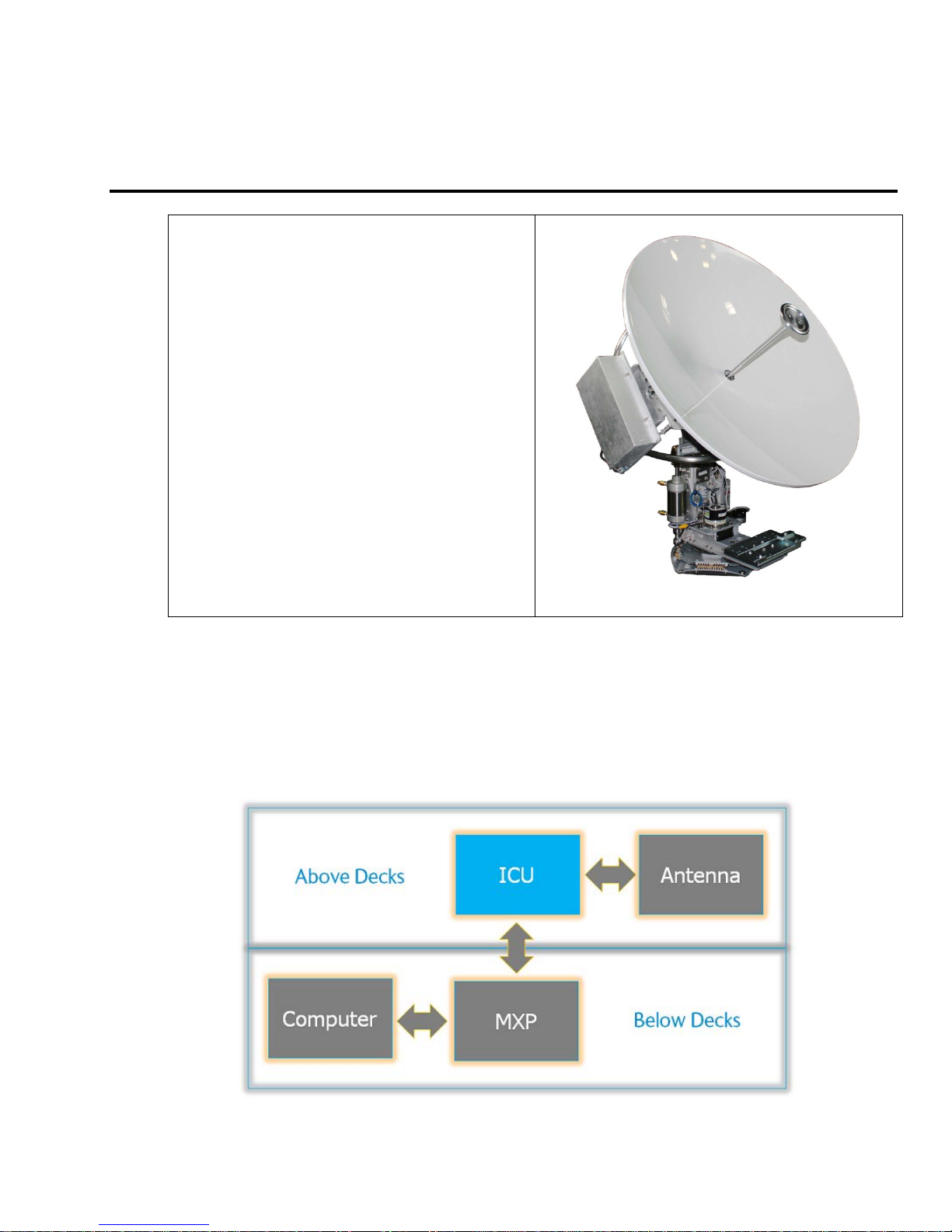
The ICU (Integrated Control Unit) is at the center of the antenna operation.
•The operator interacts with this system by way of a computer (owner-supplied).
•The computer communicates with the MXP (Media Xchange Processor).
•The MXP communicates the operator’s commands to the ICU (Integrated Control Unit), and it passes system
information back to the operator.
•The ICU controls the antenna, and monitors it.

4012 GX Operation Manual Introduction
1-2
This Page Intentionally Left Blank
Quick Start Operation 4012 GX Operation Manual
2-1
2. Quick Start Operation
If your system has been set up correctly, and if the ship has not moved since the system was used last, the system should
automatically acquire the satellite from a cold (power-up) start. Once the satellite has been acquired, the modem then should
achieve lock and you should be able to use the system.
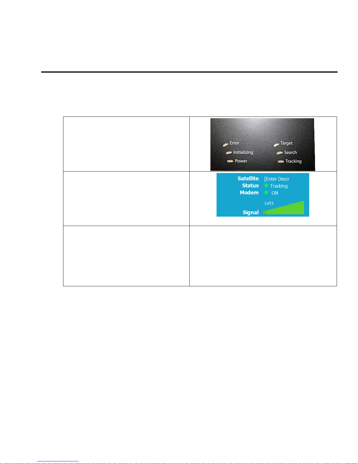
2.1. If satellite signal is found AND network lock is achieved:
1. Tracking will take over (front panel
Tracking LED will be ON) and automatically
peak the antenna position for highest
receive signal level from the satellite.
2. When the ICU has signal above threshold
AND modem has network lock the
antenna will continue to track the satellite.
3. Satellite Name (if entered), Tracking
indicator, Modem Lock indicator and
signal level (number value and bar graph)
will be displayed in the header of the MXP
GUI pages.
Upon completion of the above, the system will
continue to operate automatically, indefinitely until:
•AC power to the system is interrupted
OR
•The satellite signal is blocked OR
•The ship sails into an area of
insufficient satellite signal
strength/level.
4012 GX Operation Manual Quick Start Operation
2-2
2.2. If no signal is found:
If the system does NOT automatically find the satellite from a cold start, follow the steps below:
1. The Tracking LED will flash for a short
period of time (Search Delay) followed by
the Search LED coming ON.
2. The ICU will automatically move the
antenna in the selected Search pattern
until looking for a signal value that is
greater than the threshold value (red bar in
the bar graph).
3. Not finding a signal greater than
Threshold, the bar graph will stay red and
the antenna will reach the end of the
prescribed search pattern.
4. The antenna will retarget and the cycle will
repeat (Search Delay timeout, conduct
search pattern followed by retarget).
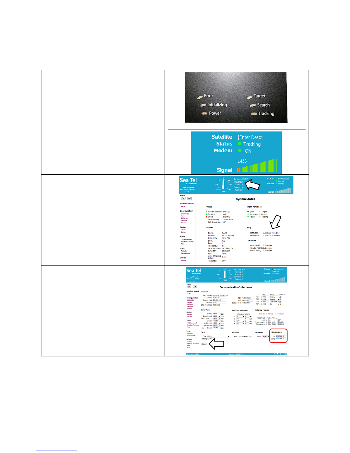
5. Check Latitude, Longitude and Heading.
These should be correct, but may be
updated if necessary.
6. Access the System Status screen.
7. Find the Latitude, Longitude and Heading
displayed values. If they are correct skip
to step 12.
8. If the Latitude & Longitude values are not
correct, access the Communication
Interfaces screen and enter the ships
Latitude & Longitude position in the fields
provided.
9. Click Save.
Quick Start Operation 4012 GX Operation Manual
2-3
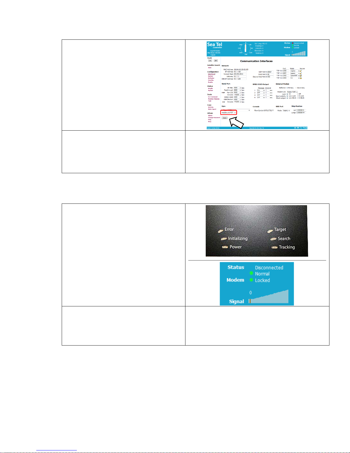
10. If the Heading value is not correct, enter
the correct value in the lower right field of
the Communication Interfaces screen.
11. Click Save.
12. Check for blockage (this is the MOST
common cause of not being able to
acquire the desired satellite).
13. Verify that the correct satellite is selected.
14. Check cable connections to assure that a
cable has not been disconnected.
2.3. If satellite signal is found but network lock is NOT achieved:
1. The Tracking LED will flash for a short
period of time (Search Delay) followed by
the Search LED coming ON.
2. The ICU will automatically move the
antenna in the selected Search pattern
until it receives a signal value that is
greater than the threshold value (red bar in
the bar graph). If signal above Threshold is
found, Tracking will take over (Tracking
LED ON) and automatically peak the
antenna position for highest receive signal
level from the satellite which has been
acquired. The system will wait for the
modem to achieve lock. If the modem
does not get lock, the antenna will resume
its search pattern.
3. If the system does not acquire the correct
satellite within the prescribed search
pattern, the antenna will retarget and the
cycle will repeat (Search Delay timeout,
conduct search pattern followed by
retarget).
4012 GX Operation Manual Quick Start Operation
2-4
4. Check Latitude, Longitude and Heading.
These should be correct, but may be
updated if necessary.
5. Access the System Status screen.
6. Find the Latitude, Longitude and Heading
displayed values. If they are correct skip
to step 11.
7. If the Latitude & Longitude values are not
correct, access the Communication
Interfaces screen and enter the ships
Latitude & Longitude position in the fields
provided.
8. Click Save.
9. If the Heading value is correct, enter the
correct value in the lower right field of the
Communication Interfaces screen.
10. Click Save.
Quick Start Operation 4012 GX Operation Manual
2-5
11. Check for blockage (this is the MOST
common cause of not being able to
acquire the desired satellite).
12. Verify that the correct satellite is selected.
13. Check for polarization drive failure.
14. Check for improper polarization
alignment/position.
15. Check cable connections to assure that a
cable has not been disconnected.
16. Check the modem for failure.
2.4. To Target a different satellite
1. To target a different satellite go to the
Satellite Search Auto screen and select
the desired satellite from the drop
down list.
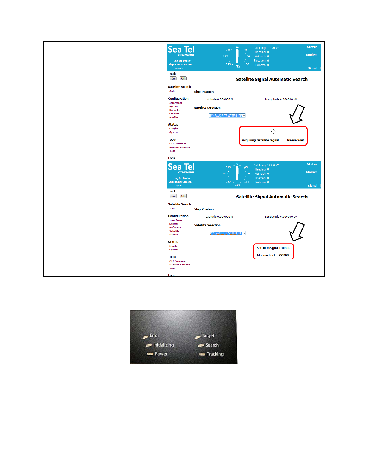
4012 GX Operation Manual Quick Start Operation
2-6
2. When you make that selection you will
see the temporary message:
Acquiring Satellite Signal…Please Wait
3. Shortly after that you will see the
temporary message:
Satellite Signal Found.
Modem Lock: LOCKED
2.5. Basic Description of the Front Panel Status LEDs
The basic description of the front panel LED states are:
Tracking -(Green LED)
ON indicates that the MXP has identified and is actively tracking the desired satellite to optimize the signal
level (AGC).
Blinking indicates that the MXP is in search delay or is analyzing a satellite signal.
OFF indicates that Tracking is OFF.

Quick Start Operation 4012 GX Operation Manual
2-7
Searching -(Yellow LED)
ON indicates that the MXP is actively searching for your satellite signal.
OFF indicates that SEARCH is OFF.
Target -(Yellow LED)
ON indicates that the antenna is TARGETING (driving) to the specified Azimuth and/or Elevation position(s).
Power -(Green LED)
ON indicates that the Antenna Control Unit is energized.
Initializing -(Green LED)
ON indicates that the Antenna is initializing. Initialization of the antenna will take approximately two
minutes.
Error -(Red LED)
ON indicates that one, or more, discrete system errors have occurred. Refer to Status – Error Code
information menu to determine which error(s) have occurred.
OFF indicates that no errors have occurred

4012 GX Operation Manual Quick Start Operation
2-8
This Page Intentionally Left Blank

4012 GX User Menus 4012 GX Operation Manual
3-1
3. 4012 GX User Menus
The following is a complete listing of all of the menu screens and the parameter setting available on each of those screens.
3.1. User Login
Log in to the MXP from the computer. If the computer has not been set up for you by the dealer, refer to the
Installation manual for instructions. When you access the MXP you will first see the login screen:
Enter the login ID as “User” and password as “seatel3”. Both of these are case sensitive.

4012 GX Operation Manual 4012 GX User Menus
3-2
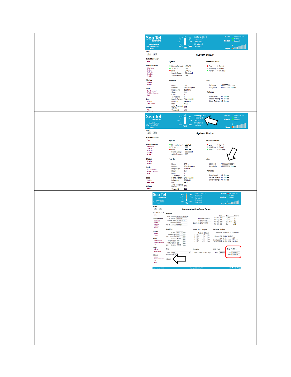
3.2. System Status
There are no entries that you can make on this screen. It is read only, and is periodically refreshed. The System Status
screen would also be displayed if you had clicked on the word “System”, under the “Status” menu group. There are five
groups of parameters on this screen
The System group on this display provides
indicators for
Modem Rx Lock
Tx Mute
Error
This display can also be viewed in the header of
every menu screen.
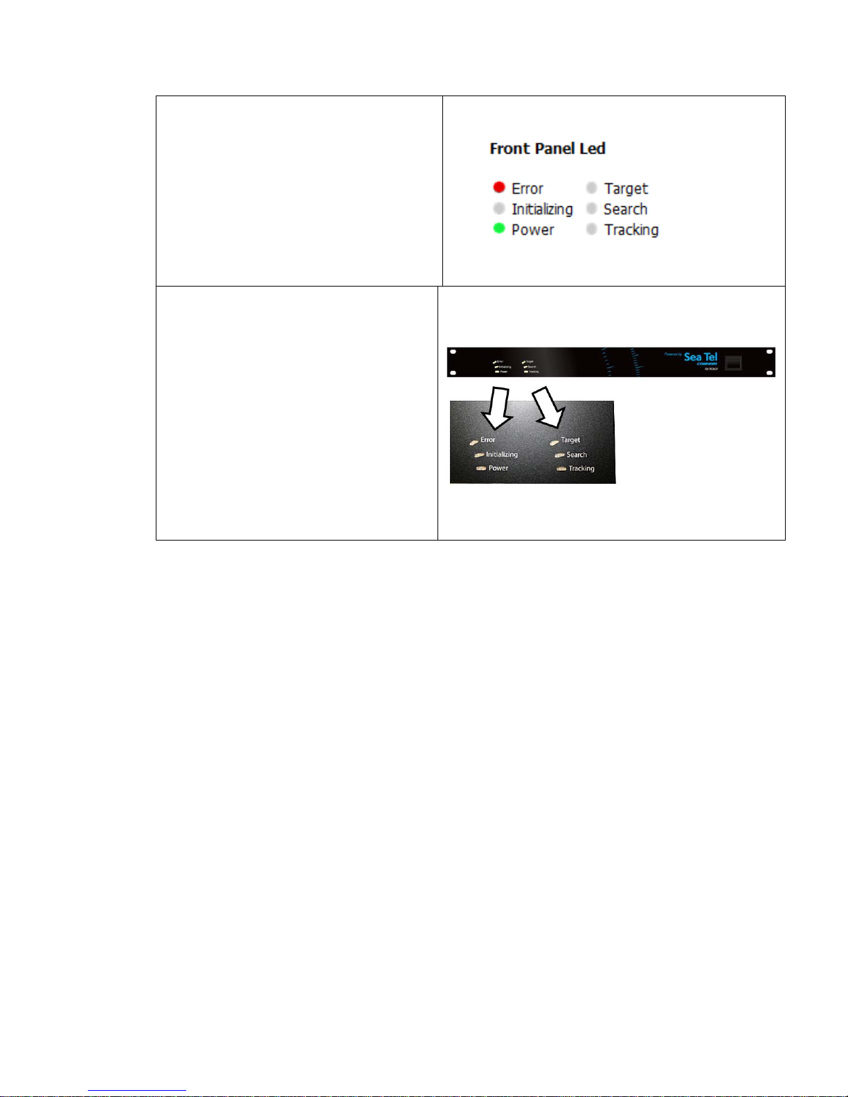
4012 GX User Menus 4012 GX Operation Manual
3-3
The Front Panel LED group on this display
provides the same six indicators that are on the
front panel of the MXP
Error
Initializing
Power
Target
Search
Tracking
These represent the six LEDs seen on the front
panel of the MXP.
4012 GX Operation Manual 4012 GX User Menus
3-4
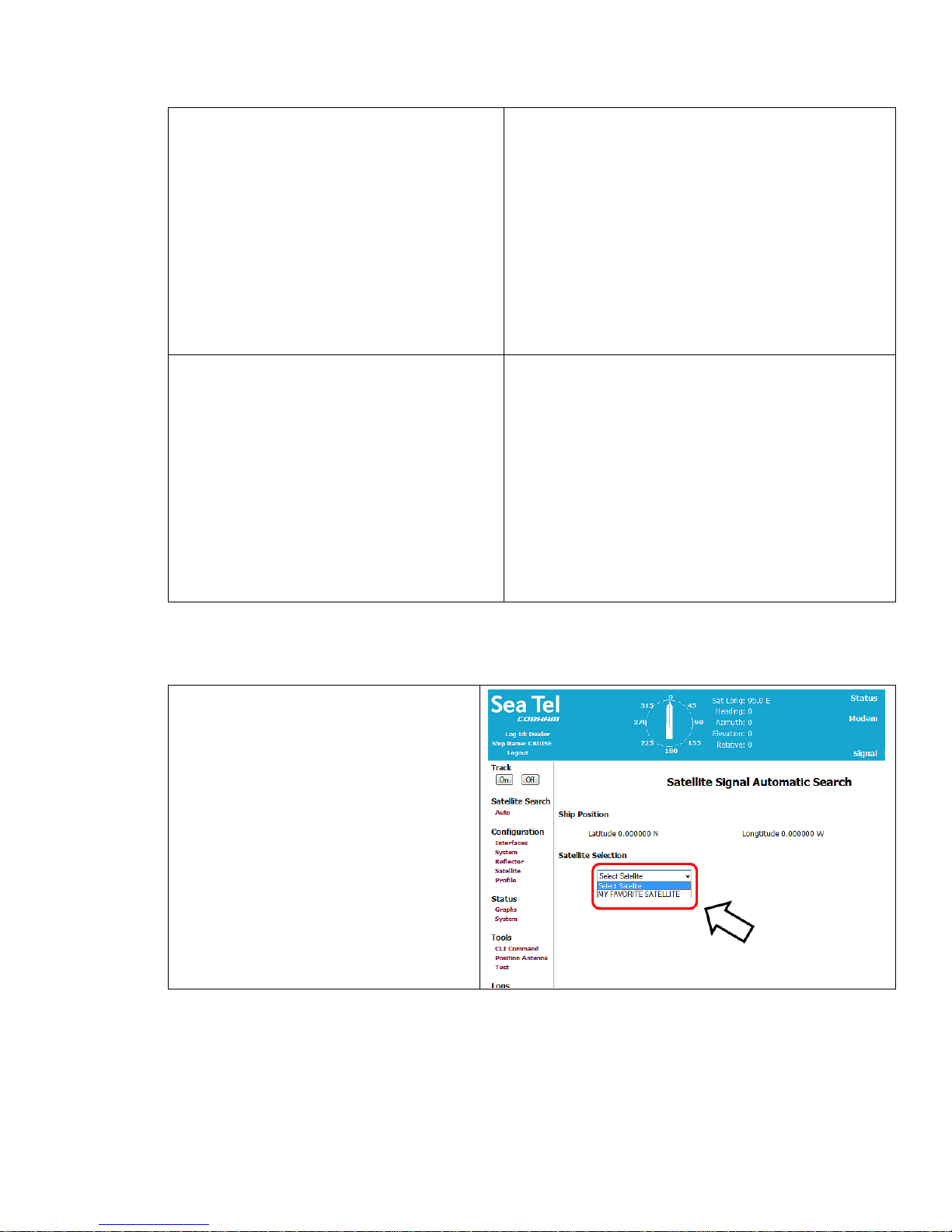
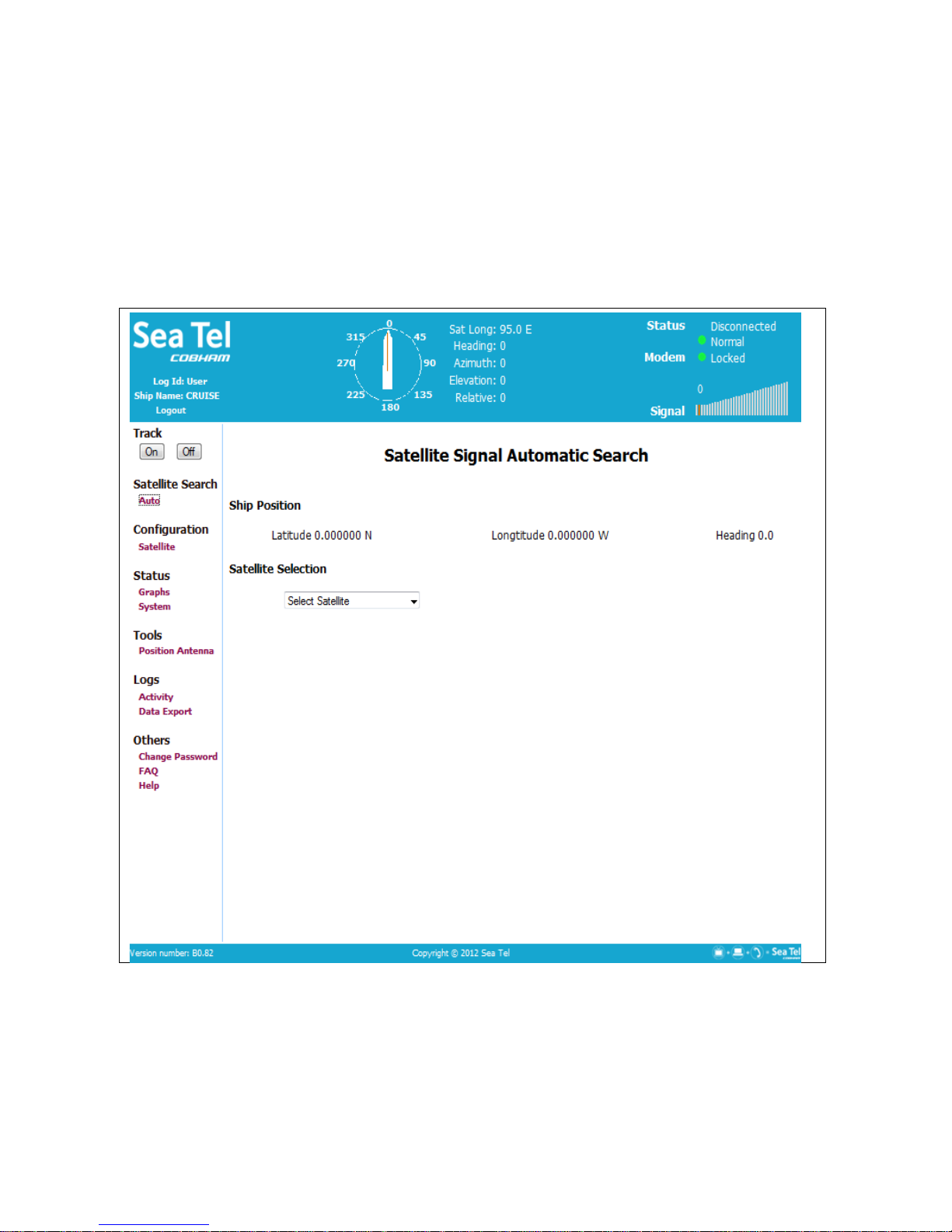
3.3. Satellite Signal Automatic Search
The ship’s position (Latitude & Longitude) and Heading are displayed in the header of every menus screen. The
Latitude & Longitude are also displayed on this screen where you view the satellite which is currently selected, or select
the satellite you want to target.
Here you can select a satellite by clicking on the drop down menu and choosing the desired satellite from this
saved/configured satellites in the drop down list.
Once a satellite is selected, targeting and inclined searching is performed automatically.
Clicking on the drop down box will allow you to see the selections.
This is the method of satellite selection that will most commonly be utilized by the users, under the “User” Log-in.
Other manuals for 4012 GX KU-BAND
3
Table of contents
Popular Transmitter manuals by other brands


E+E Elektronik
E+E Elektronik EE310 operating manual

Hitachi
Hitachi EC701HP Operation manual

SJ
SJ MSLG200 Quick installation manual

HK Instruments
HK Instruments CDT-MOD-2000 Duct Series installation instructions

FUTABA
FUTABA R3006SB quick start guide

Endress+Hauser
Endress+Hauser PROFIBUS DP Proline 100 Brief operating instructions


