SJ MSLG200 Operating and maintenance instructions

Temperature sensor/ transmitter shall be installed by professional
engineers, technicians and other qualified personnel, please read
carefully the content and important information provided by this
installation guide and label before installation.
Temperature sensor / transmitter is powered by an external
power supply, the power supply should be in accordance with
relevant standards stipulated by energy limitation circuit, and pay
attention to the high-voltage that may exist in the circuit.
Using temperature sensor/transmitter in dangerous situations,
product installation, using and maintenance should comply with
installation guide and relevant provisions of national standards.
Attention please! Disassemble the instruments under the
condition of normal atmospheric pressure only.
Safety Precautions
Product Usage
Horizontal pipe installation
Bending pipe installation
Install at top of container
To ensure measurement accuracy, the influence of medium flow
direction, wall thickness and outer shape of protection tube, insertion
depth, as well as pipe material, heat insulation material of container
insulation layer should be considered when install temperature
sensor/ transmitter.
!
!
!
Direct installation
Process connection
Welding
Holing on the pipeline according to
the protection tube outer diameter.
Insert appropriate length when welding.
Straight thread
L1
L2
L1
L2
Adopting gaskets roots sealing,
the thread length should be less than
the base length(L1<L2); adopting
gaskets end face sealing, the thread
length should be more than the base
length(L1<L2)
Movable thread
Matched movable thread can
realize insertion length adjustment and
low-intensity seal.
Tri-clamp
Usually choosing gaskets with
material of PTFE, silicon rubber and
FKM which conform to hygienic
standards
Flange
Choosing gaskets according to
medium features and temperature range
and lock evenly.
Taper thread
Sealing with teflon tape or sealant
glue. When thread lock hard, there is a
small part of space
!Hygienic process connection Tri-clamp is approved by 3-A
hygienic certificate.
The gaskets of tri-clamp and all the wetted parts comform
with FDA standards.
@
!
ExdIICT6 GYB16.1606x
When using a spanner to screw
hexagon bolt, the maximum torque force
can not exceed 50Nm.
!
Label
MN:MSLG200-WRT-R1-T1R3-FC-Q2-G6M01-D2L0500
SN:1605-086-018-2-C1236
IN:20~- 100
OUT:4~20mA
ACC:0.5%
SUPPL
SIN JIA ENTERPRISE CO., LTD.
Y:24VDC
Φ=8mm
L-500mm
temperature transmitter 2016/05/ 2 6
1/:+
2/:-
3
4
1
2
3
4
5
1
2
5
Measuring range
Power supply
Signal outline type
Explosion proof mark
Certificate
i Important information
74-06
The axis of protection tube and vertical
pipeline should be consistent. Contact
media reversely and the insertion length
should be half of the pipe diameter at
least.
!Angle of inclination: 45- 90°
The protection tube should be inserted
with enough length to avoid error
caused by temperature stratification.
Install at side of container
The protection tube should be inserted
with enough length to avoid error
caused by contacting the wall of
container.
Protection tube should contact media
obliquely and reversely, the insertion
depth should be half of the pipe
diameter at least.
Light-weight pressure transmitter
can be mounted directly on the
pressure leading tube. Bracket is not
needed.
Temperature transmitter / Quick installation manual
2022.12
74-06
SIN JIA ENTERPRISE COMPANY LIMITED Tel: +886-2-2550-4512 Email: [email protected] Website: www.sj-gauge.com
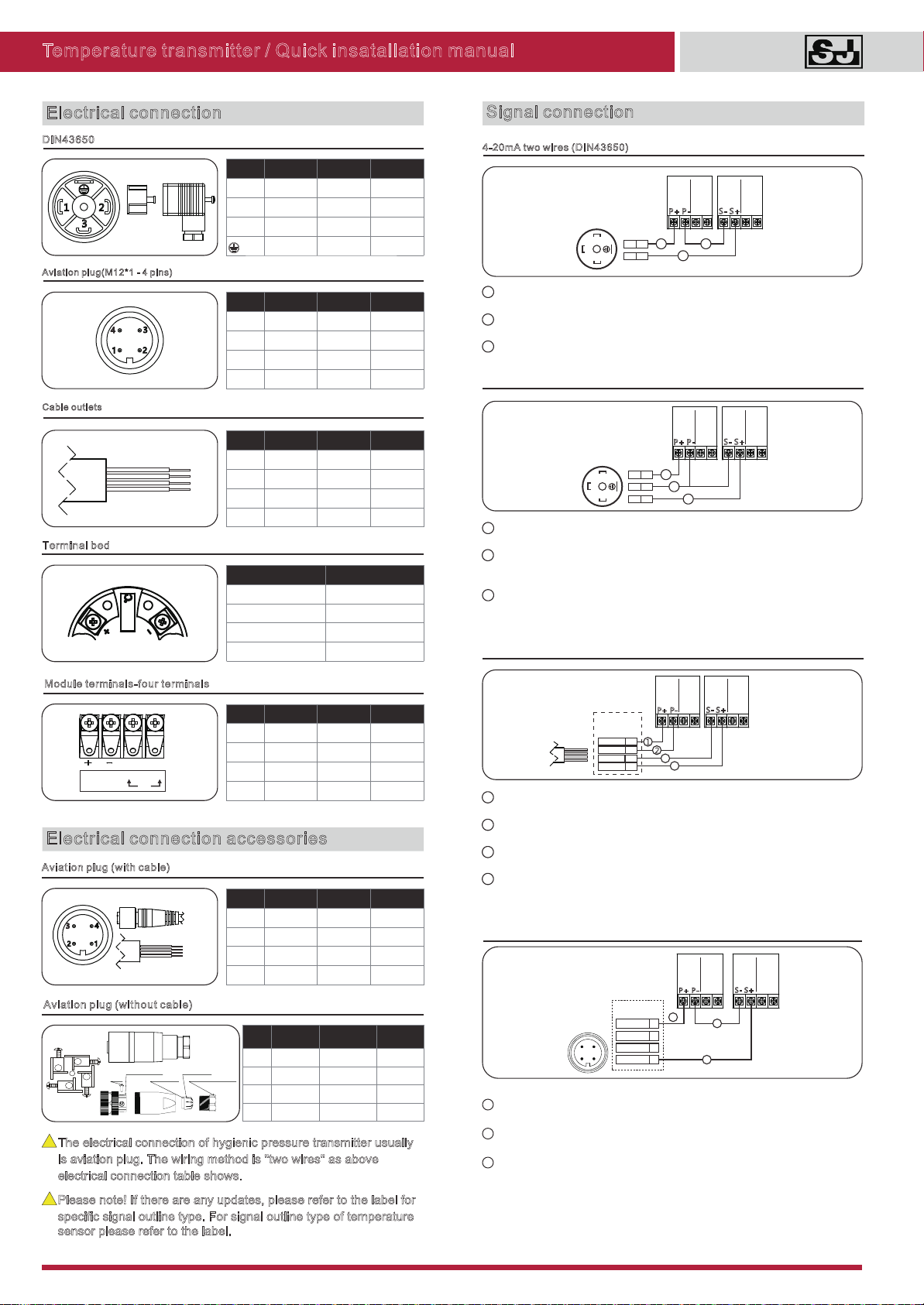
Electrical connection
DIN43650
Aviation plug(M12*1 - 4 pins)
Terminal bed
Module terminals-four terminals
1 2
Cable outlets
Red
Black
Blue
Yellow
4
1
3
2
AB
+ -
AB+ -
A
Lable Two wires
1Power+
2Power-
Aviation plug (with cable)
Brown
Black
Blue
White
3
2
4
1
Electrical connection accessories
!
The electrical connection of hygienic pressure transmitter usually
is aviation plug. The wiring method is "two wires" as above
electrical connection table shows.
Aviation plug (without cable)
Label
Two
wires
Three wires
F
our wires
1Power+ Power+
P
ower+
2
Signal-
3
Signal+
Signal+
4Power- Power-
P
ower-
!
Please note! If there are any updates, please refer to the label for
specific signal outline type. For signal outline type of temperature
sensor please refer to the label.
Signal connection
4-20mA two wires (DIN43650)
1 Connect the positive power supply (P+) to the positive power supply (P+) of
temperature transmitter (terminals 1);
2 Connect the negative power supply (P-) of temperature transmitter (terminals 2) to
the positive signal module (S+);
3 Connect the negative signal module (S-) to the negative power supply (P-)
+
-
P+ P- S- S+
1
2
1
2
31
2
3
L
abel Two wires Three wires
F
our wires
1
Power
+
Power
+
Power+
2
Power- Power-
Power-
3
Signal
+
Signal+
S
ignal-
Label
Two wires
Three wires
Four wires
1
Power+Power+
P
ower+
2
S
ignal-
3
Signal
+
Signal+
4
Power-
Power-
P
ower-
Label
Two
wires
Three
wires
Four
wires
R
ed Power+Power+
P
ower+
Black
Power-
Power-
Power-
B
lue Signal+
Signal+
Yellow
Signal-
Label
Two wires
Three wires
Four wires
+
Power+Power+
P
ower+
-
Power-
Power-
Power-
A
Signal+
Signal+
B
S
ignal-
Label
Two wires
Three wires
Four wires
1
/Brown Power+Power+
P
ower+
2/White
Signal-
3
/Blue Signal+
Signal+
4/Black
Power-
Power-
Power-
1
2
3
compression bolt
clamp ring
rubber ring
screw
block terminal
4
Block terminal
rewoP
langiS
Three wires current/voltage signal (DIN43650)
+
-
P+ P- S- S+
S+
1
2
3
1
2
3
1
2
3
1 Connect the positive power supply (P+) to the positive power supply (P+) of
temperature transmitter (terminals 1);
2 Connect the negative power supply (P-) of temperature transmitter (terminals 2) to
the negative power supply (P-), and connect the negative signal module (S-) to
negative power supply (P-);
3 Connect the positive signal module (S+) of temperature transmitter (terminals 3)
to the positive signal module (S+);
Four wires, current/voltage signal (cable)
+
-
P+ P- S- S+
S+
S-
Red
Black
Yellow
Blue
34
1 Connect the positive power supply (P+) to the positive power supply (P+) of
temperature transmitter (red wire);
2 Connect the negative power supply (P-) of temperature transmitter (black wire) to
the negative power supply (P-)
3 Connect the negative signal module (S-) of temperature transmitter (Yellow wire)
to the negative signal module (S-);
4 Connect the positive signal module(S+) of temperature transmitter (blue wire) to
the positive signal module (S+).
Label
4-20mA two wires (aviation plug with cable)
1 Connect the positive power supply (P+) to the positive power supply (P+) of
temperature transmitter (terminals 1/brown wire);
2 Connect the negative power supply (P-) of temperature transmitter
(terminals 4/black wire) to the positive signal module (S+);
3 Connect the negative signal module (S-) to the negative power supply (P-)
+
-
P+ P- S- S+
13
4
3
212
Label
Blue/3
Brown/1
White/2
Black/4
Temperature transmitter / Quick insatallation manual
2022.12 SIN JIA ENTERPRISE COMPANY LIMITED Tel: +886-2-2550-4512 Email: [email protected] Website: www.sj-gauge.com
rewoP
langiS
rewoP
langiS
rewoP
langiS
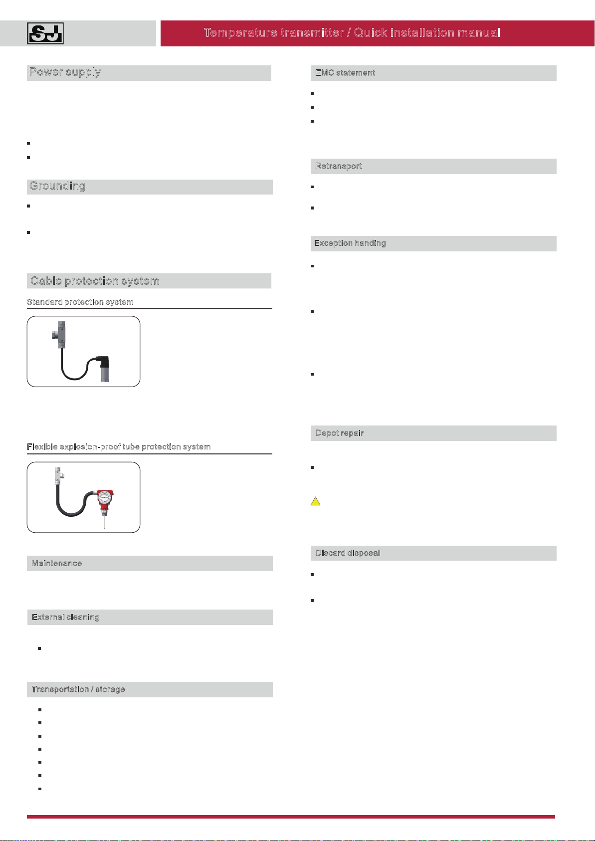
Standard protection system
Flexible explosion-proof tube protection system
Cable protection system
In order to avoid the liquid flowing
along with the cable to flow into the
terminal box or result in waterproof
joint effusion, an U-shaped ring
needs to be configured between
pull box and temperature
transmitter as the picture shows,
and please ensure the U-shaped
bottom is under the temperature
transmitter. Considering the
maintenance and replacement,
enough cable length needs to be
Using flame proof temperature
transmitter in dangerous situations,
please use metal flexible explosion-
proof tube to connect the signal
cable into pull box and lead to the
safety zone.
Maintenance
Requires no maintenance
External cleaning
Please notice the following when cleaning:
Use washing agent which will not damage to the instruments
surface and seal ring.
Transportation / storage
Do not store at outside
Keep dry and dust-free
Do not expose to the corrosive medium
Avoid solar radiation
Avoid mechanical shock and vibration
Storage temperature: -40~100°C
Maximum relative humidity: 95%
EMC statement
EMC equipment instructions 2014/30/EU.
CE mark suggests the instruments are in line with EU standards
Users need to ensure the whole equipment conform to all the
applicable standards.
Depot repair
Please finish the following steps before the depot repair:
Removal of all the residues which would be harmful to human
health, such as inflammable, poisonous, cancerigenic and
radioactive substances.
Warning! Do not return the instruments if can not ensure the
dangerous residues are removed, eg: the dangerous residues
permeate into cracks or spread to the plastic.
!
Discard disposal
The instrument is not restrained of WEEE instruction 2002/96/EG
and laws of relevant countries.
Please pass the instrument to specialized recycling companies
other than local recycling points.
Retransport
Keep clean of the temperature transmitter. Stay away from any
Please adopt proper package to avoid damage in transportation.
dangerous medium!
Power supply
Independent linear direct-current power supply is suggested to be adopted for
the power supply of temperature transmitter, over large resistive load will result
in a large pressure drop, so it requires to calculate the all-in resistance of
signal cable, display meter and other record and display equipment, to ensure
the voltage provided to the temperature transmitter accord with normal
operating requirements.
Standard current signal output: 12-30VDC,
1~5VDC voltage output: 12-30VDC.
Grounding
Using cable with shielded twisted-pair signal has the best effect. To avoid
ground loop, shielded layer adopts single-end grounded.
Transient resistance built-in module is effective only in the case of good
grounding. Metal shell and internal grounding terminals are used to the nearest
Measurement signal is abnormal which should judge the process pressure is
abnormal, measuring system error or influence of installation environment or
abnormal in the pressure transmitter, then analyze the reason and take
corresponding measures.
No signal output, process pressure changes but no measurement
corresponding change, or , it may be an abnormalchange does not correspond
pressure transmitter, it needs to check the power supply voltage, wiring, power
consumption and load resistance whether they meet normal operating
requirements. Also need to check if there is leaks and pressure impulse line
blockage, shut-off valve not turned on, etc.
Signal output error is too big or it exceeds need to checkthe normal range,
the power supply voltage, power consumption and load resistance whether
they meet normal operating requirements, the measuring range setting, if
adjustment is correct. Also need to check if there is leaks and pressure impulse
line blockage, shut-off valve not turned on, rapid temperature fluctuations, etc.
Exception handing
Temperature transmitter / Quick installation manual
2022.12 SIN JIA ENTERPRISE COMPANY LIMITED Tel: +886-2-2550-4512 Email: [email protected] Website: www.sj-gauge.com
Popular Transmitter manuals by other brands


Teledyne
Teledyne 300P operating instructions

EMX Industries
EMX Industries WEL-200K operating instructions

Endress+Hauser
Endress+Hauser RMA 422 operating instructions

Sennheiser
Sennheiser TV Clear Transmitter 2 instruction manual

Novus
Novus NP600 instruction manual

American Fibertek
American Fibertek MT-1890 instruction manual