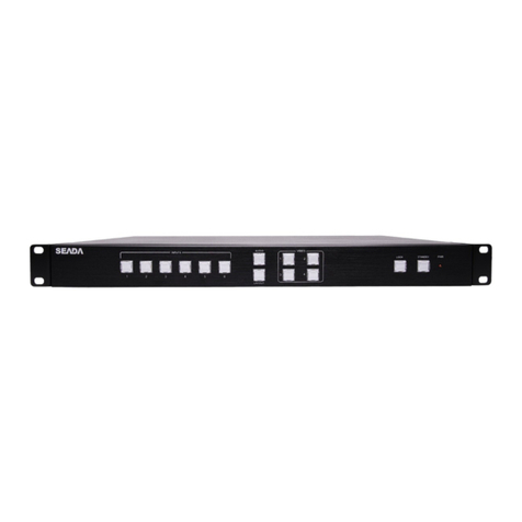
Seada G44 Series User manual

G44 User Guide
This user guide provides basic instructions for setting up SEADA G44 video wall controllers using its
management software.
Document No. SD-MA-027
Document Version: 02

G44 User Guide
Table of Contents
1. Product Introduction.......................................................................................................................3
1.1. Product profile ........................................................................................................................3
1.2. Product capability ...................................................................................................................3
1.3. Specification & Parameters.....................................................................................................3
2. Hardware Overview ........................................................................................................................5
3. G44 Software ..................................................................................................................................6
3.1. Matrix Switch ..........................................................................................................................6
Audio route.............................................................................................................................9
3.2. Advanced Switch.....................................................................................................................9
3.3. Signal settings .......................................................................................................................12
3.4. FineTune: PQ & Position .......................................................................................................12
3.5. OSD Control...........................................................................................................................13
3.6. TV Wall..................................................................................................................................16
3.7. Web Control..........................................................................................................................17
4. Front Panel....................................................................................................................................20
4.1. LCM display...........................................................................................................................20
4.2. Audio Input Select (Default: Inner).......................................................................................20
4.3. Output Audio Select (Default: Inner)....................................................................................21
4.4. Audio Switch .........................................................................................................................21
4.5. Video Switch..........................................................................................................................22
4.6. Video + Switch.......................................................................................................................22
4.7. Input Type Setting.................................................................................................................23
4.8. Output Type Setting..............................................................................................................23
4.9. Output Resolution Setting ....................................................................................................24
4.10. Recall.....................................................................................................................................24
4.11. Save As ..................................................................................................................................25
5. Command Lines.............................................................................................................................26
6. Troubleshooting............................................................................................................................29
6.1. No Connection ......................................................................................................................29
6.2. No Output .............................................................................................................................29
6.3. Black screen ..........................................................................................................................29

G44 User Guide
1. Product Introduction
1.1. Product profile
⚫G44 video wall controller can support up to 4 inputs/4 outputs.
⚫It supports HDMI, DVI, VGA, YPbPr, CVBS signal input/output through DVI-U jacket.
⚫It support RS232 communication interface, through the special PC tool to control the matrix
signal switching, monitoring the working state of the matrix, set the signal resolution, etc..
⚫Seamless switching available;
1.2. Product capability
⚫Support 4 inputs and 4 outputs,4 L/R audio inputs and 4 L/R audio outputs;
⚫Support HDMI/DVI, VGA, YPbPr, CVBS input;
⚫Support HDMI/DVI, VGA, YPbPr, CVBS output;
⚫Support a maximum resolution of 1600 x 1200@60hz;
⚫Support RS232 port control
⚫Support network port control
⚫Support IR remote control
⚫Support front panel button control
⚫Scalar inside, output resolution control available;
1.3. Specification & Parameters
Input
Interface
Signal
DVI-U
HDMI
HDMI -1.3
DVI
DVI 1.0
VGA
800x600,1024x768,1280x768,1280x800,1280x1024,136
0x768,1400x1050,1600x1200,1920x1080
YPbPr
576i50,720p50,720p60,1080i50,1080i60,
1080p50,1080p60
CVBS
PAL,NTSC
Output
Interface
Signal
DVI-U
HDMI
HDMI V1.3A
1024x768,1280x1024,1360x768,1280x720
1600x1200,1920x1080,1680x1050
DVI
DVI 1.0
1024x768,1280x1024,1360x768,1280x720
1600x1200,1920x1080,1680x1050
VGA
1024x768,1280x1024,1360x768,1280x720
1600x1200,1920x1080,1680x1050
YPbPr
1080p60,720p60
CVBS
PAL/NTSC
Control
RS232
D-sub 9
Baud rate:9600
Size
W*D*H
430(mm)×220(mm)×44(mm)

G44 User Guide
Power
DC
12V/3A power adapter
Power
consumption
25W
Temperature
Operating
temperature
0℃—40℃

G44 User Guide
1
2
3
4
2. Hardware Overview
Model: G44-DVI
1 –Display
2 –Input Buttons
3 –Output Buttons
4 –Function Buttons
Back Panel includes 4 DVI-U Inputs and
Outputs, Ethernet control port, 2x Serial ports
and 4 3.5 mm captive screw connectors for
audio inputs and outputs
LCM

G44 User Guide
3. G44 Software
Users can run the G44.exe software directly without
installation. It requires password authentication:
Default password for Administrator is: 111111
Default password for User is: 000000
There are 7 main tabs in this software: Matrix Switch, Advanced Switch, Signal Setting, Fine Tune, OSD
CTRL, TV Wall, Network Setting.
3.1. Matrix Switch
Users can configure the G44 device and connect the device to control PC in this section.
3.1.1. Connect to the G44 via UART
Connect the G44 to the control PC with a serial cable
1. Click the dropdown menu right of Port to select the COM port.
2. Click the button right of Status to connect to the device (the button will change from
Disconnected to Connected)
3. If the COM port does not exist, then the PC tool will show a
message of ‘COM x not detected!’. If this message occurs, you
should start from step 1 after you connect a serial cable to the
computer.

G44 User Guide
4. If the device or the connection is faulty, then a message will
occur as follows after 3 seconds. Please check if your device or
hardware connection is correct.
5. If all is right, the PC tool will read some information
from the device. It probably takes 5 seconds and it will
show ’Reading: All information success!” when
finished.
3.1.2. Connect to the G44 via Network
The default IP address for G44 controller is 192.168.0.247 Users need to change the IP address of
the control PC to the same network segment as the G44.
•Change the ‘Obtain an IP address automatically’
to ‘Use the following IP address’ to set up a static IP address of TCP/IPv4 in Ethernet Properties
➢IP address: any address between 192.168.0.2 and 192.168.0.254 except the address which has
been taken by the G44
➢Subnet mask: 255.255.255.0, Default Gateway: 192.168.0.1
•Once the control PC IP address having been set up, connect PC to either the RJ45 ports of
G44 controllers via a network cable and then press the Connect button to connect the device.
3.1.3. Matrix Switch Routing
Users can switch and assign different inputs to the
selected outputs in the matrix. The name of the
input/output can also be changed by selecting the
default name –Input1/Video-Output1 and
replacing it with the chosen name.
3.1.4. Allset, Recall, Save As and Reset
The G44 unit has 32 modes (or
presets) already saved. Selecting
one of them from the recall Menu will select that specific preset.
If you would like to save a preset you have already created, select the dropdown menu and choose
which slot you want to save it in.
Finally, the Allset dropdown menu helps the users select a single input to be displayed on all of the
screens (i.e. Allset Input 4 would display Input 4 on Output 1, Output 2, Output 3 and Output4.)

G44 User Guide
The reset button, resets the default settings of the unit –Input 1 mapped to Output 1, Input 2
mapped to Output 2 etc. (Including the audio)
3.1.5. Presentation Mode
From the dropdown menu in the top-right corner, users can select either Matrix mode or
Presentation mode.
•Matrix Mode –The Inputs and their audio source are mapped to each other. Meaning that
Input 1 will have the audio source from Input 1, Input 2 will have the audio source from
Input 2 etc.
•Presentation Mode –This allows the user to control the audio source separately –The video
screen can display input 2, however the audio source can be any of the inputs (including
input 2)
Video and audio can be controlled separately(default):
Video and audio can be controlled together. And then you can select which audio channel will be
controlled.

G44 User Guide
Audio route
Click to control audio route. And the blue button represents current route information.
NOTE: Audio output X has two type (L/R and Inner).
3.2. Advanced Switch
The PC tool support automatically switch the input source periodically for the output port in order to
facilitate the demonstration functions needed in some scenarios.
Operation guide is as follows:
1. Click the output port that needs configuring (Also we can press ‘Ctrl’ or ‘Shift’ first, then click to
select more output ports)

G44 User Guide
2. Press ‘Ctrl’ or ‘Shift’ first, then click to select input ports
3. Click “-->” button to add the input ports selected in step 2 .
4. Check the output ports that need to automatically switch input source periodically.
5. Configure automatically switch Switch frequency: default 2000ms

G44 User Guide
All outputs send combine: default not checked
unchecked: Switch all outputs one by one.
checked: Switch all output ports’ input at the same time in a switch operation.
Note: Switch one input one by one if there’re many input ports selected.
Wait others finished then start next loop: : Only can be set when ‘All outputs send combined’ is
checked
unchecked: When the number of the selected input ports of some output is not the same,
immediately start next loop when one output finished a switching loop.
checked: All outputs start a new loop together. When the number of the selected input ports
of some outputs is not the same, not start next loop until other outputs finish theirs current
switching loop.
Send cmd only one loop: stop automatically switch when a loop is finished.
Select all outputs: Quickly check or uncheck all output ports.
6. Click ‘Start’ button to start automatically periodically switch.
7. Automatically periodically switch is ongoing…
8. Click ‘Stop’ button to stop automatically periodically switch when needed. If ‘Send cmd only one
loop’ is checked, it will stop after one loop is finished.

G44 User Guide
3.3. Signal settings
In the signal settings tab, the user can see the Input Resolution and Input Type as well as the Output
Type and Resolution. The read all function will recognize the type and resolution automatically,
however if the user wants to change the input resolution, then you can adjust it manually via the
dropdown menu.
Additionally, you can also manually read one Input/Output at a time –pressing the read button next
to the selected input will only read that input alone.
3.4. FineTune: PQ & Position

G44 User Guide
3.4.1. PQ Control
This section highlighted in red allows the user to fine-tune the settings of their screen from the G44
software.
The dropdown menu at the top of the section allows the user to select which screen to apply the
settings to
The read option reads the settings of the monitor/screen that are already in place and adjusts the
values in the software, while the reset button will reset the settings to their default after they have
been manually adjusted.
3.4.2. Position Control
The section highlighted in blue allows the user to fine-tune the position of their screen. Parameters
such as H Start V start, and H Size and V Size will allow the user to adjust the starting position and
the size of the screen (H –Horizontally, V - Vertically)
The dropdown menu at the top of the section allows the user to select which screen to apply the
settings to
The read option will read the monitor/screen settings that are already in place and adjust the values
in the software and the reset button will reset to the default values after the values have been
manually adjusted.
3.5. OSD Control

G44 User Guide
3.5.1. Text Content
There are several modes of OSD –Normal, 3x3 and
3x4.
With the normal mode there will be only one column
displayed at a time. Normal mode allows for more
lines to be added as well. Simply press enter to go to
a new line
3x3 and 3x4 modes add additional columns that can
be displayed on the OSD.
3x3 –Repeats the Text Content 3 times in 3 columns
3x4 –Repeats the Text Content 3 times in 4 columns
When the Sync Time checkbox is ticked, then the date and time will be displayed. The user can select
on what line both the Date and the Time to appear and what their format is.
Additional settings can be found underneath for the time update settings. The “Update Every __ sec”
setting will tell the OSD how often to update the time (every 1 second functions like a digital watch
and updates every second, while anything over 1 second will update only as often as specified by the
user)
•Set –This will apply the current settings for the OSD Text Content and will display it onto the
screen
•Read –This function will read any existing OSD settings on the screen.
•Import –This allows the user to import any OSD settings from another control PC (Any
settings that have not been saved on the device itself)
•Export –The user can export any of the OSD settings from this software into an .osd file
•Reset –This resets the OSD settings to factory default.
The mode save and mode load settings allow the user to load a pre-existing OSD preset and to save
the current one into one of the 8 slots (Note: These mode slots are different than the Matrix Switch
modes and there are only 8 of them)

G44 User Guide
3.5.2. Text Settings
The user can apply the OSD settings to one
screen at a time. The Board Address dropdown
menu dictates which screen is the OSD being
setup on.
Display will hide or show the text
Transparent when selected off will apply a solid
background to the text so that it is more easily
readable. When selected on it will remove the
solid background and only the text will remain.
The alpha slider dictates how opaque the text is –0 being invisible and 255 being 100% opacity.
Text Color will change the color of the text only. This setting has 5 color slots, however when clicking
the dropdown menu and clicking on one of the 5 colors, it will select that slot and open the following
menu:
This allows the user to customize the colors they want.
The BACKGROUND COLOR is similar to the Text Color setting; however, it only applies to the
background (Only works if the Transparent setting is off)
Position can be relative or absolute. Relative will allow the customer to align the text –
Top/Middle/Bottom vertically, and/or Left/Middle/Right horizontally. Absolute will allow more
flexibility for the customer as it allows for X and Y positioning of the text.
Font allows the user to select from three different fonts –SimHei, KaiTi, SimSun. The dropdown
menu next to the font controls the size of the text.
Set applies the changes.

G44 User Guide
3.6. TV Wall
In the TV WALL tab, the user can design the setup they have in front of them to mirror it in the
software. This allows for some video wall functionalities of the unit –screen stitching. Right-clicking
on the screens will bring up the additional options menu.
•Screen Stitching - This combines the selected screens into one and displays the selected
input across all of the stitched screens. For example, in the setup below 2x2, if all of them

G44 User Guide
are stitched, then the input selected by the user will be displayed across all of the 4 screens
(Note: this is not the same as duplicating a single input on each output)
•Cancel Stitching –This will undo the stitching and will revert to the screens being individual.
•Input Select –Similarly to the video routing matrix, this allows the user to control which
output is displayed on which screen (Note: Selecting an input on any of the screens when
stitched will display it on the stitched screen and not on the individual screen)
•Output Select –The user can control which screen should be mapped to which output
•Output Type –Allows the user to adjust the type of the output –HDMI, VGA, HDMI etc.
•Output Format –Controls the resolution of the output
•Horizontal adjust –Lets the user adjust the horizontal position of the screen
•Vertical adjust –Lets the user adjust the vertical position of the screen
The user can save the designed scene (preset) and load it later via the Load
Scene and Save Scene dropdown menu. This allows for easier switching
between layouts –for example a stitched layout, a layout of 2x2 individual
screens, a 2-screen stitching with 2 individual screens etc.
3.7. Web Control
(1)Condition: do not know the matrix IP address: Click on the Network Settings
page, and then click Search Device, and then select the device that found, click Open
Website to open the web control web site, or can input the IP on the web browser,
then enter the username: admin Password: admin, then can control the matrix switch
functions via website;
NOTE: The computer IP and matrix IP must be in the same segment and the same
local area network; For example, the matrix’s IP is 192.168.1.xxx, then the computer
IP must be 192.168.1.yyy; Otherwise need to change the matrix’s IP or the
computer’s IP

G44 User Guide
Note: the browser must support HTML5 feature, which must be IE10 and above;
(2)Condition: know the matrix IP address: Input the IP on the web browser, then enter the
username: admin Password: admin, then can control the matrix switch functions via
website;
When successfully connected following interface should appear:

G44 User Guide
Route switch is the same as in the PC Tool.
1- switch language to Chinese (to switch back to English click again)
2 –Chose the Work Mode and Audio Control
3 –Set all outputs on one input, save layouts and recall them as well as reset the device.
4 –Read an input signal type
5 –Read an output, change the type and set a format
IP Config
In ‘IP Config’ tab you can change all ip configurations:

G44 User Guide
4. Front Panel
Input/Output Buttons
Video/Audio Select Buttons
Type
Format
Recall
Save
→
Enter
4.1. LCM display
LED light flashing once when device receives a valid key pressing.
Continuous key pressing should be within 5 seconds, and the LCM screen will show the video route
info if timeout happens.
LCM screen can show two lines which consists of 16 characters each.
Some key words information as below:
V: Video route info;
A: Audio route info;
T: Type;
F: Format or resolution;
4.2. Audio Input Select (Default: Inner)
Keys operation: AUDIO + INx + →+ ENTER
Description: Select audio type: Inner or L/R.
Display: (LED light flashing once when a valid key pressed)
1. Press AUDIO, then the LCM screen will show function menu
S
E
T
I
N
P
U
T
A
U
D
I
O
P
R
E
S
S
I
N
1
2
3
4
2. Press INx to select which input port will be set, and the LCM screen will show the current
setting first.
3. Press →to change the setting (Inner or L/R).
4. Press ENTER to take effect.
This manual suits for next models
1
Table of contents
Other Seada Monitor manuals
