Seaeye SI-MCT01 User manual

Thruster SI-MCT01
Instruction Manual
Issue 7
© SEAEYE 2006
Unauthorised reproduction of this publication or any part thereof without prior permission is strictly
prohibited

THIS PAGE IS INTENTIONALLY BLANK

Thruster SI-MCT01
1
CE
In respect of the Electromagnetic Compatibility Directive 89/336/EEC, attention
is drawn to the following:
•The SEAEYE SI-MCT01 'as delivered' complies with the essential protection
requirements of the EMC Directive 89/336/EEC.
•In order to ensure that the SEAEYE SI-MCT01 complies with the Directive
when installed for operational use, the installation instructions contained
within this Technical Manual must be adhered to.
•The end user of (or authority responsible for) the installation of the SI-MCT01
becomes responsible for the complete installation's compliance with the
Directive, particularly under the following circumstances:
oadditional equipments are used in conjunction with the system (unless
they are supplied by SEAEYE MARINE LTD), or
omodifications are made to the system (or part thereof), or
osurface equipment is removed from its 'as-built' enclosures for
subsequent installation in third-party racks or consoles.
•During Maintenance Procedures, when the system is operated outside its
normal operating environment and/or screened enclosures are opened for
access, the equipment may emit, or be susceptible to, electromagnetic
interference (EMI). The equipment should be sited away from safety critical,
essential communication, or navigation systems during such activities. It is
advisable to site the surface equipment away from critical electronic systems
at all times.
•It is recommended that electrical power for the SEAEYE SI-MCT01 is
provided using a dedicated supply which is not also used to power safety
critical, essential communication, or navigation equipment.
•Any questions in respect of the Compliance of any SEAEYE MARINE LTD
equipment with the EMC Directive, or any field reports of EMC related faults,
should be addressed to the Technical Director at SEAEYE MARINE LTD.
Seaeye House, Lower Quay Road, Fareham, Hampshire, PO16 0RQ, England

Thruster SI-MCT01
2
WARRANTY STATEMENT
Products sold by SEAEYE MARINE LIMITED (hereafter referred to as SEAEYE)
are guaranteed to the original purchaser as follows:
Subject to the exceptions and upon the conditions stated hereafter, SEAEYE
agrees to correct, either by way of repair, or at SEAEYE’s sole discretion, by
way of replacement, any defect of material or workmanship which develops as
follows:
•SEAEYE MCT Thruster Motors : 12 months,
•SEAEYE parts returned on completion of Repair : 3 months,
of dispatch of the product to the original purchaser by SEAEYE or it’s
authorised representative, provided that the investigation and factory inspection
by SEAEYE disclose that such defect developed under normal and proper use
and not due to fair wear and tear or misuse by the user for its intended purpose.
Repair or replacement are the exclusive remedies under this guarantee, and
further provided that the guarantee granted hereby shall not include parts,
materials, or spare parts that SEAEYE considers as expendables under normal
operating conditions.
The exceptions and conditions mentioned above are as follows:
1. SEAEYE make no guarantee concerning components or accessories that
are not of it’s own manufacture. All goods sold and manufactured by other
manufacturers are sold subject to the manufacturer’s guarantee, which
shall be assigned to the purchaser or authorised representative. SEAEYE
in so far as it is appointed by the agents of a manufacturer to carry out
repair work under such guarantees will, where it considers it appropriate,
carry out the necessary repair work on terms agreed by SEAEYE and
purchaser or authorized representative having regard to the liability of the
manufacturer under it’s guarantee. Notwithstanding anything in this
paragraph, any goods sold but not manufactured by SEAEYE are not
supplied with any warranty whether express or implied and warranty
imposed by common law or statute including the warranty of merchantable
quality and the implied warranty of fitness for a particular purpose
contained in the UK Sales of Goods Act 1979 Section 14 is expressly
excluded although SEAEYE undertakes to take reasonable care in
supplying suitable goods and giving particulars of performance.
2. SEAEYE shall be released from all obligations under its guarantee in the
events that repairs or modifications are made by persons other than its own
authorised service personnel or trained and authorized representative,
unless such repairs or modifications by others are made with prior written
consent by a Director of SEAEYE. In the event of a failure, and the

Thruster SI-MCT01
3
purchaser or agent authorized by the purchaser or the operator fails to take
prompt and reasonable action to prevent further damage, SEAEYE will not
accept any responsibility for consequent damage. “Normal and Proper use”
of a product includes without limitation performing routine preventative
maintenance in accordance with the appropriate instructions within the
appropriate service and/or maintenance manual.
3. SEAEYE products, systems and parts are Ex-works at the company’s UK
site. SEAEYE is not responsible for carriage/shipment/duty/taxes/
insurance or any other costs for any product, system or part either
dispatched to or from the company’s UK site.
4. There are no guarantees which extend beyond those expressly provided
for herein and the aforesaid guarantee and SEAEYE’s obligations and
liabilities there under are in lieu of, and the customer waives, all other
guarantees, express or implied, and all other liabilities therefore arising by
law or otherwise, including without limitation any implied guarantee of
merchantability or fitness for a particular purpose, and all obligations and
liabilities with respect to loss of use, revenue or profit, or indirect,
consequential or incidental damages of any kind and from manufacture,
sale, handling, shipment, repair, maintenance or replacement of said
products.
5. Representations and warranties made by any person, including dealers
and representatives of SEAEYE that are inconsistent or in conflict with the
terms of this guarantee (including but not limited to the limitations of the
liability of SEAEYE as set forth previously), shall not be binding upon
SEAEYE unless reduced to writing and approved by an officer of SEAEYE.
6. SEAEYE’s liability arising from the sale or use of a product sold by
SEAEYE shall be limited to SEAEYE’s cost of correcting defects, as
provided herein, or the total cost of such product as shown on the purchase
order pursuant to which it was purchased, whichever is less. All such
liabilities will terminate upon expiration of the guarantee period.
7. This guarantee shall be provided for and governed by the prevailing laws of
England.

Thruster SI-MCT01
4
General Information
Specifications: SEAEYE reserves the right to change specifications at any time
without due notice and without incurring any obligation to incorporate any new
features in any of it’s previous products, whether or not they have been sold.
Damage in Shipment: Each new product is carefully examined and checked
prior to dispatch from SEAEYE’s premises. It should be carefully examined and
operationally tested on receipt by the receiving party. If the product is damaged
in any way, then a claim should be lodged with the carrier. New or repaired
product that has been damaged in transit should not be returned to SEAEYE
without first obtaining specific shipping instructions from SEAEYE.
Repairs: If any fault develops, the following steps should be taken:
•Notify SEAEYE and give full details of the difficulty. Include in this notification
the model type and its serial number. On receipt of this information SEAEYE
may elect to either issue service instructions or provide full shipping data for
the return of the equipment.
•After shipping instructions are supplied, forward the product(s) prepaid and
repairs will be estimated and the client informed prior to any repairs to the
fault(s) being carried out.
•The client may then issue SEAEYE an approved purchase order to cover the
costs of the repair, if the fault has been caused by misuse or is not under
guarantee.

Thruster SI-MCT01
5
Introduction
The SI-MCT01 is the culmination of Seaeye’s proven brushless DC motor
technology and impressive new developments in magnetics and materials
sciences. RS485 communication facilitates the rapid integration of the SI-
MCT01 into all manner of subsea applications from ROV and AUV propulsion to
prime mover applications such as pumps. With simplicity and versatility in mind
the SI-MCT01 can be controlled simultaneously with up to 128 similar nodes
from a single serial port.
Specifications
Nominal Voltage: 48VDC
Nominal Power: 300W
Forward Thrust @ 300W: 13 kgf
Reverse Thrust @ 300W: 12.8 kgf
Propeller Speed @ 300W: 960 r.p.m
Propeller Diameter: 180 mm
Weight in Air: 4.3 kg (including propeller and nozzle)
Weight in Seawater: 2.5 kg (including propeller and nozzle)
Depth Rating: 300 m
Control Signal: RS485
Connector: 5-Way Connector
2 x Power
2 x Telemetry
1 x Earth
Thruster SI-MCT01
6
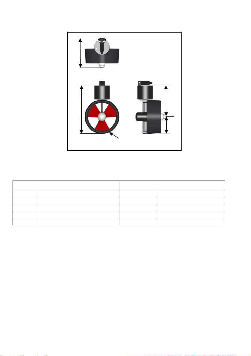
Fig. 1. Dimensions
Connection
External Internal
Pin 1 Brown Red/White +48/+24 V
Pin 2 Red Yellow Telemetry A
Pin 3 Orange Blue Telemetry B
Pin 4 Yellow Black/Grey 0 V
Pin 5 Green Green Earth
Telemetry MUST be fused at: F250mA
Supply MUST be fused at: F8A(T)
Size = mm
205
132
Ø220
192
337

Thruster SI-MCT01
7
Fig. 2. Thruster Connection

Thruster SI-MCT01
8
Seaeye Marine Thrusters - Electronics Explained
The Thruster Control Loop
To maintain constant speed under varying loads, Thrusters must operate within
a closed loop control system.
Open loop systems apply power to the motor in proportion to the operator
demand. The actual motor shaft speed, however, is dependent upon loading
and will change under different operating conditions. Only in calm, minimal sea
currents and tides would the vehicle remain stable, otherwise Auto function
control would be very unreliable.
In a closed loop control system, the power applied to the motor is determined by
the difference between the user demand and the actual shaft speed.
For a fixed user demand:
•Increased propeller loading causes the motor to slow down. This increases
the difference between actual and demand speed which is a difference
known as error. This error is measured by the thruster electronics feed
back loop and causes more power to be applied to the motor until the actual
speed equals the demand speed reducing the error to zero.
•Decreased propeller loading causes the actual speed to rise above that
required, the difference or error is negative, causing a reduction in applied
power until the motor shaft speed falls and the error is again reduced to zero.
Control loop INPUT signal
The propeller speed is determined by the mark-space ratio of the SPEED input
signal to the thruster. The actual shaft speed (as determined by the speed
feedback circuit) is subtracted from the input demand signal to produce an error
voltage, which is proportional to the difference between the required speed and
the actual propeller speed.
Overload trip
Jamming of the propeller or gradual fouling causes the thruster current to rise
above safe levels. If left unchecked, either gradual or instant current growth will
exceed the permitted levels causing thruster overheating or destruction of the
drive FETs. A current sensor provides indication of a fault condition. A
temporary over current trip may be cleared by reversing the direction of the
Thruster. If the overload condition persists, then the trip condition will continue
preventing damage to the thruster.
Thruster SI-MCT01
9
SI-MCT01 Thruster Control
Introduction
This document details the telemetry specification for the SI-MCT01 Thruster.
Node Configuration
The network of nodes uses a Master/Slave configuration. The controller Input
being the master and all other nodes are slaves. The master node initiates
communication and the slave will then reply.
Packet construction
There are two types of packets a Surface to Subsea (controller to thruster) and
Subsea to Surface (thruster to controller).
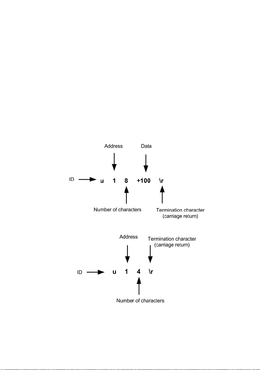
Fig. 3. Example of surface to subsea
Fig. 4. Example of subsea to surface

Thruster SI-MCT01
10
Field name Field
width Example
Character Description
ID 1
u ID of thruster node. Lower case indicates
surface to subsea, uppercase indicates
subsea to surface.
ADDRESS 1
1 Address of node. Total of 35 different
addresses for each type of node 0 to 9, then
A to Z. Address 0 is reserved for broadcast
to all nodes of ID specified. Only 35 nodes
of any type allowed.
NUMBER OF
CHARACTERS 1 8 Number of characters used in packet. This
includes the encoding characters and
carriage return. Therefore a miniumum of 4
will always be sent. Total of 36 characters
can be sent 4 to 9, then A to Z.
DATA 0 to 32 +100 Data sent in packet. This can only be up to
32 characters long.
TERMINATION 1
\r Terminating character ‘\r’ (carriage return).
The example u18+100\r specifies the following information
uthruster node addressed from surface to subsea
1address 1
88 characters in total used in this packet
+100 a demand of +100% required
A correct acknowledge reply from the node to the handcontroller would be U14\r
Uthruster node reply
1from address 1
44 characters in total used in this packet
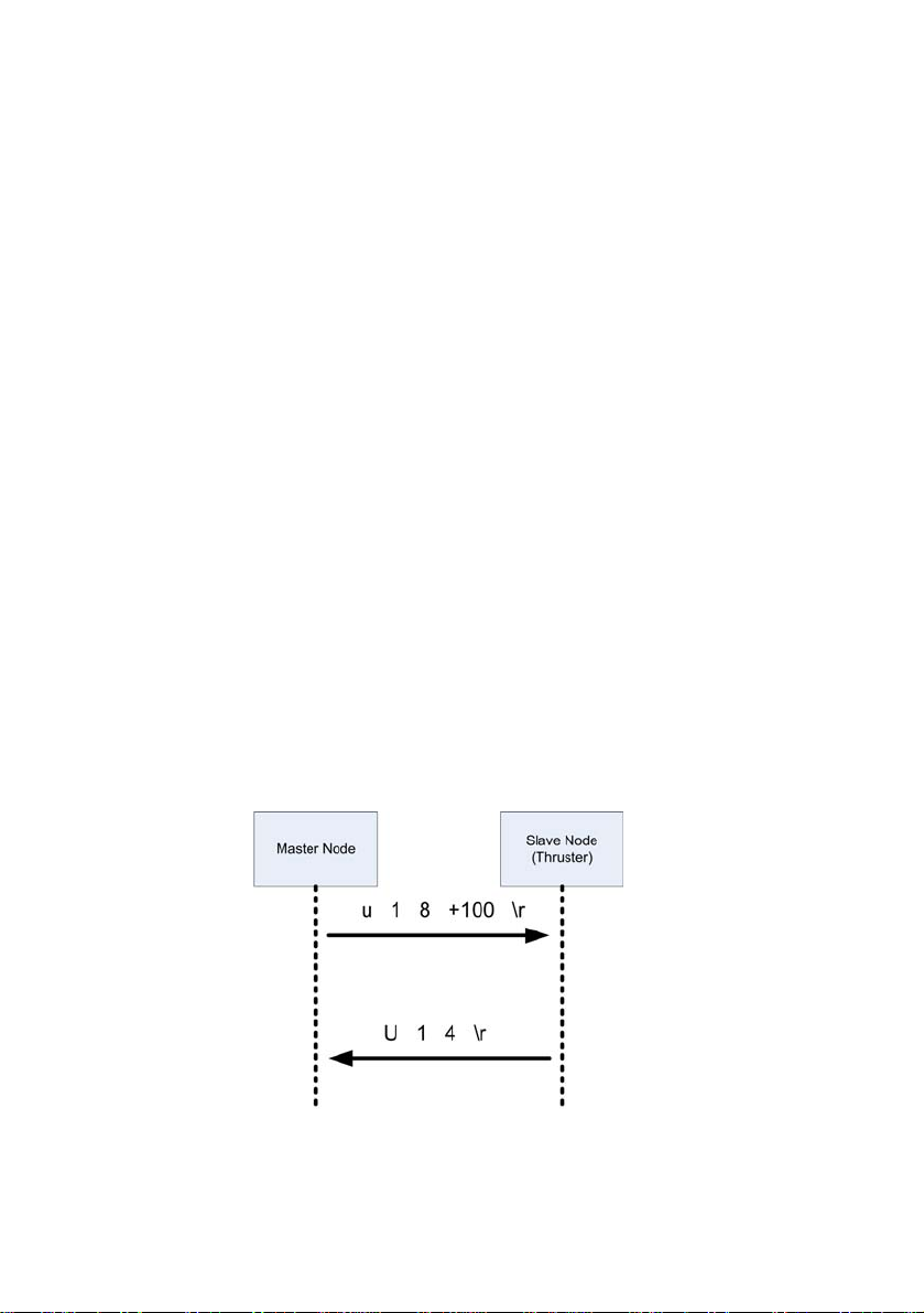
This sequence of packets shows the demand from the handcontroller to thruster
1 of +100%. The thruster then replies with a acknowledge packet.

Thruster SI-MCT01
11
The following table gives the various commands available for the MCT1 thruster.
Data
Command Value Function Reply Notes
+ 0 to 100 Forward demand 0 to +100% Ack
- 1 to 100 Reverse demand 0 to –100% Ack
? R Request output speed 0 to 6250 Motor rpm (divide by 5
to give propeller rpm)
? C Request motor current 0 to 10 0 to 6 Amps
? b Request baud rate
? h Request total time run hH mM H = hours M = minutes
? n Request node name string Up to 8 chars
? v Request version number mmnn mm - major number
nn - minor number
x 0 Disable eeprom write
x 1 Enable eeprom write
z Reset node Non zero on
success
n 0 to F Set node address Non zero on
success Eprom Write must be
enabled
b 0 Set baud rate 57600 (default) Non zero on
success Eprom Write must be
enabled
b 1 Set baud rate 4800 Non zero on
success Eprom Write must be
enabled
b 2 Set baud rate 9600 Non zero on
success Eprom Write must be
enabled
b 3 Set baud rate 19200 Non zero on
success Eprom Write must be
enabled
b 4 Set baud rate 38400 Non zero on
success Eprom Write must be
enabled
Thruster SI-MCT01
12
Control Notes
The commands are in standard ASCII format, 1 Start, 8 Data, 1 Stop, 0 Parity,
user selectable Baud Rate {57600 default) and the terminating character ‘\r’ is a
single carriage return.
To set either a new address or baud rate eeprom write must be enabled. The
new address or baud rate will not take effect until the node is reset.
If the thruster does not receive a command for 1 second or more the thruster
demand is zeroed.
Communication Example
The example u18+100\r specifies the following information
uthruster node addressed from surface to subsea
1address 1
88 characters in total used in this message
+100 a demand of +100% required
A correct acknowledge reply from the node to the handcontroller would be
U14\r
Uthruster node reply
1from address 1
44 characters in total used in this message
The figure shows the sequence of messages for a demand from the controller to
thruster address 1 of +100%. The thruster then replies with an acknowledge
message.

Thruster SI-MCT01
13
Thrust Direction due to Demand
The following diagram shows the direction of thruster travel depending on the
demand given.
Thruster SI-MCT01
14
Maintenance - Thruster Propeller Replacement
Frequency of Task
The propeller should be checked before and after thruster useage. The
propeller should be replaced when there is obvious damage to propeller.
Introduction
The purpose of this check is to ensure that the thruster is working efficiently
Tools Required
The following tools may be required:
•Allen Keys (common sizes)
Parts Required
The following parts may be required:
•Thruster Propeller (Part Number P01780).
•Loctite 222.
•Lubricating Oil (Aqua Shield or similar).
Procedure
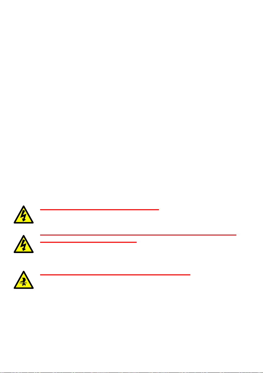
WARNINGS:
DANGER OF FATAL ELECTRIC SHOCK. BEFORE REMOVING OR
OBTAINING INTERNAL ACCESS TO THE EQUIPMENT ISOLATE
ALL THE UNITS POWER SUPPLIES.
POSSIBILITY OF FATAL ELECTRIC SHOCK AND DANGER TO
PERSONNEL AND EQUIPMENT. BEFORE SWITCHING ON THE
THRUSTER ENSURE THAT THE SYSTEM IS FULLY ASSEMBLED
AND OPERABLE AND NO MAINTENACE ACTIVITY IS IN
PROGRESS.
DANGER TO PERSONNEL AND EQUIPMENT. THRUSTERS
MOTORS MAY OPERATE WITHOUT WARNING WHEN THE
SYSTEM DC SUPPLY IS ENERGISED. ENSURE THAT THE
THRUSTER IS CLEAR OF ANY OBSTRUCTION AND PERSONNEL
PRIOR TO ENERGISING THE DC SUPPLY.
Thruster SI-MCT01
15
Proceed as follows:
1. Visually examine the propeller to see if replacement is completely
necessary.
Fig. 5. Propeller Assembly
2. Remove the socket head screw, spring washer and propeller retainer.
Fig. 6. Retainer Parts
3. The propeller assembly can now be removed; it may be difficult to remove
as it is magnetically coupled.
Propeller
Retainer

Thruster SI-MCT01
16
Fig. 7. Propeller Assembly Removed
4. The propeller assembly can now be dismantled, they are holes either side
of the nose cone and one in the magnetic coupling, these can be used for
the ‘C’ spanners to disassemble.
Fig. 8. Propeller Coupling Assembly
5. The propeller can now be changed.
Nose Cone Propeller Magnetic Coupling

Thruster SI-MCT01
17
6. When fitting the magnetic coupling to the nose cone, use Loctite 222 on
the nose cone threads.
Fig. 9. Propeller Fitment
7. Use the ‘C’ spanners to tighten the assembly together.
8. Apply a small amount of lubricating oil (Aqua Shield or similar) to the
internal propeller bearing assembly.
Fig. 10. Propeller Assembly
9. Refit the propeller assembly to the thruster using the retaining socket
screw and spring washer.
Fig. 11. Thruster Propeller Fitment
10. When fully tightened, there should still be a slight lateral movement of the
propeller to ensure that it is not ‘locked’ onto the thruster shaft.
Apply
Loctite 222
Apply
Lubricating
Oil

Table of contents


