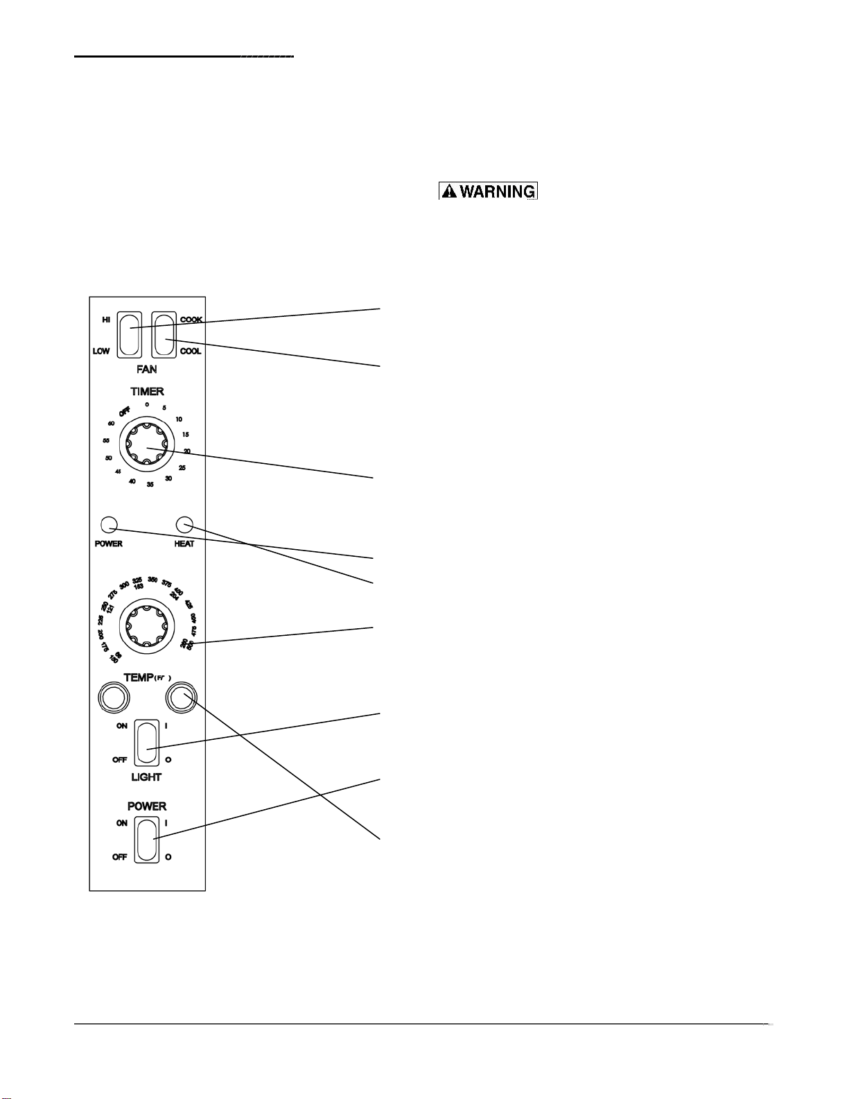
Installation and Operation of Electric Convection Oven
INSTALLATION INSTRUCTIONS
The oven should be placed in an area that is free
from drafts and accessible for proper operation
These installation instructions are for the use of qualified
installation and service personnel only. Installation or
service by other than qualified personnel may result in
damage to the oven and/or injury to the operator.
Refer to the Oven Placement Clearances Chart
before installing the oven.
Qualified installation personnel are those individuals,
firms,companies or corporations which either in personor
throughan agent is engaged in and responsible for:
OVEN PLACEMENT CLEARANCES CHART
Left Side
Rear
1"
3"
8"
0"
3"
8"
The installation of electrical wiring from the electric
meter, main control box or service outlet to the
electrical appliance.Qualified installation personnel
must be familiar withall precautions required and
have complied with all requirements of state and
local authorities having jurisdiction. See: National
Electrical Code, ANSI/NFPA70.
B. DELIVERY AND INSPECTION
Core Pro does everything with in its power
to insure you received your oven in good condition.
They are strapped down on heavy wooden skids and
Surrounded by heavy “tri-wall” carton stop revent shipping
damage. They have all been carefully inspected before
they were packaged and consigned to the carrier.
Upon delivery of your Core Pro oven:
Look over the shipping container,carefully noting any
Exterior damage on the delivery receipt, which must
also be signed bythe driver/ delivery person.
Uncrate and check for anydamage, which was not
evident on the outside of the shipping container.
This iscalled concealed damage.The carrier must be
notified within five(5) days of the delivery ofthe oven
and the carton, skid and allpackaging materials
must be retained for inspection.
It isalso important not to obstruct the natural flow of
ventilation air if the oven is to operate properly. This
oven should not be installed on a curb base or sealed
to the wall. Either condition can restrict theflow of air to
or prevent proper ventilation of the blower motor. The
blower motor has a thermal protection device,which will
trip, because of excessive ambient temperatures at the
back of the oven. This condition should be corrected
immediately to avoid damaging the oven permanently.
Before making any connections to the oven, check the
specification plate to be sure the oven specifications
concur with the voltage andphase to be supplied to
the oven.
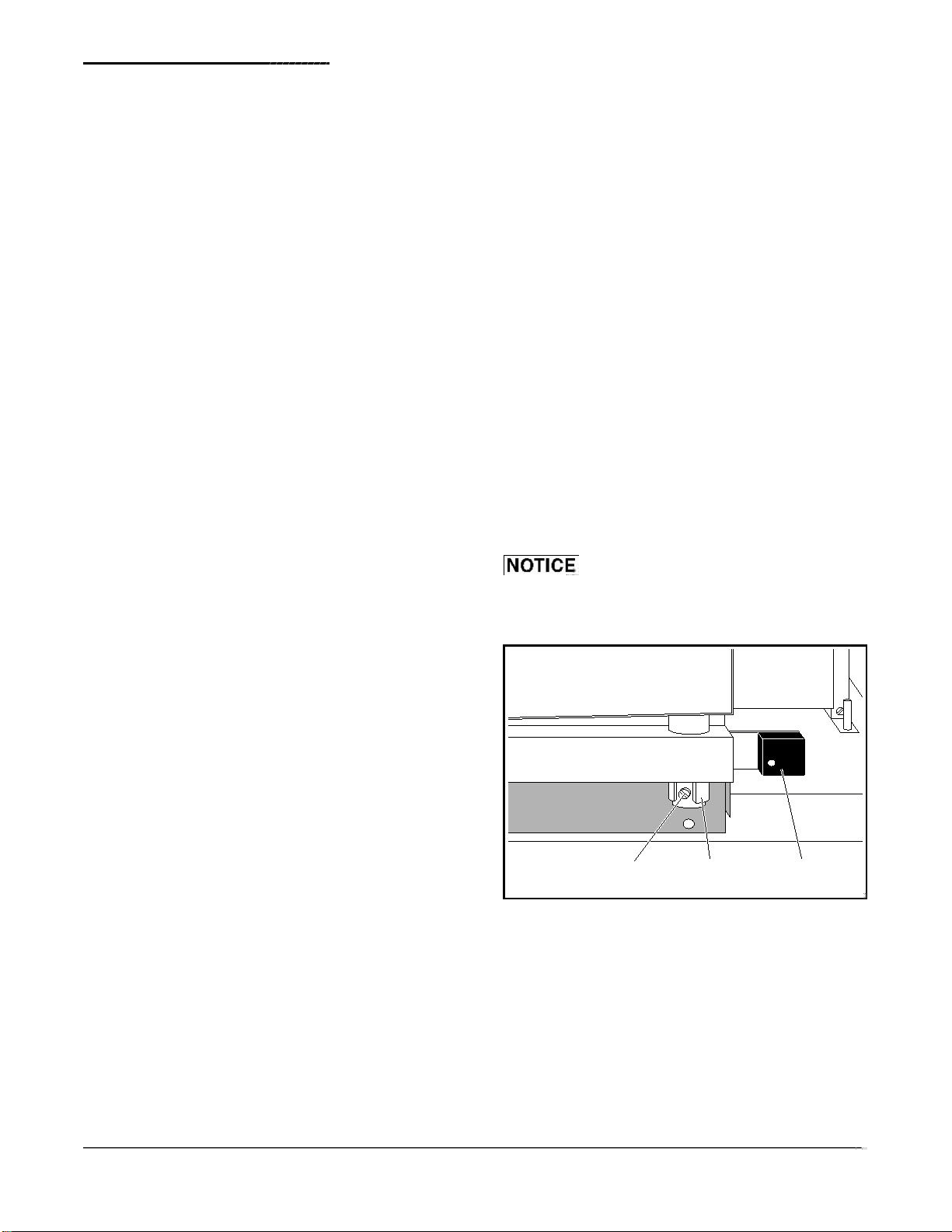
The specification plate islocated behind the lower front
panel.To access the specification plate,loosen the four
screws below the doors, and pull the panel outward.
Thespecificationplatebearingtheoven’sserialnumber
is attached to the underside of the upper ledge above
the control panel.
D. ELECTRICAL CONNECTIONS
The oven issupplied for connection to a 208V 3
PHASE grounded circuit. The electric motor, oven
lights,indicator lights andc ontrol circuits are connected
internally and require no secondary power supply.
Before making any connections to these units, check
the specification plate to assure that the voltage and
phase of the oven is compatible with the electrical
supply. When installing, all ovens must be electrically
grounded in accordance with local codes or in the
absence of local codes, with the National Electrical
Code, ANSI/NFPA 70 (in Canada – CSA Std. C22.1).
Wiring diagrams are located inthe control compartment
Ikon cannot assume liability for Loss ordamage
suffered intransit. The carrier assumes full responsibility
for delivery in good order when the shipment was
accepted. However, we are prepared to assist you in
filing your claim.
C. LOCATION OF THE OVEN
Proper planning and placement of the oven will give you
the best results in terms oflong-term user convenience
and satisfactory performance. We urge you to give
adequate thought in the placement of your oven prior
to itsarrival.