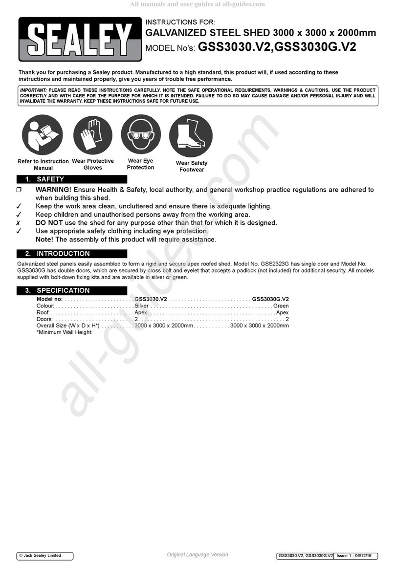
Sealey GSS2323 User manual

WARNING! Ensure Health & Safety, local authority, and general workshop practice
regulations are adhered to when building this shed.
Keep the work area clean, uncluttered and ensure there is adequate lighting.
Keep children and unauthorised persons away from the working area.
DO NOT use the shed for any purpose other than that for which it is designed.
Use appropriate safety clothing including eye protection.
Note! The assembly of this product will require assistance.
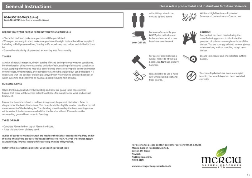
Before commencing the assembly, we recommend that you read the instructions thoroughly. Your
new shed comes with all the holes pre drilled to make for fast easy assembly. We recommend
that you assemble the shed using a trestle table or sawhorses and planks. This will ensure that
you are working off the ground and make it easier for you. Assembly is a two person job and
should not be attempted in windy conditions.
Step 1: Check all parts against the component list.
Step 2: Assemble the rear wall panels.
Step 3: Assemble the side wall panels.
Step 4: Assemble the roof wall panels.
Step 5: Assemble the front wall panels.
Step 6: Assemble front door.
Step 7: Fit the panels together.
Concrete Slab: It is recommended that your new shed is secured to a concrete slab as per the
specications in this manual.
INSTRUCTIONS FOR:
GALVANIZED STEEL SHED
MODEL No: GSS2323
Thank you for purchasing a Sealey product. Manufactured to a high standard this product will, if used according to these instructions
and properly maintained, give you years of trouble free performance.
IMPORTANT: PLEASE READ THESE INSTRUCTIONS CAREFULLY. NOTE THE SAFE OPERATIONAL REQUIREMENTS, WARNINGS AND
CAUTIONS. USE THE PRODUCT CORRECTLY AND WITH CARE FOR THE PURPOSE FOR WHICH IT IS INTENDED. FAILURE TO DO SO MAY
CAUSE DAMAGE AND/OR PERSONAL INJURY AND WILL INVALIDATE THE WARRANTY. PLEASE KEEP INSTRUCTIONS SAFE FOR FUTURE USE.

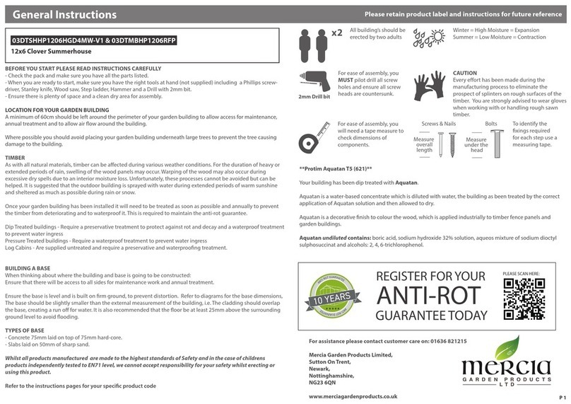
Concrete slab: Please ensure that your site is level. It is recommended that your slab is 100mm
thick and you use builders plastic and F52 reinforcing mesh. We recommend that you make your
slab 100mm bigger than the base dimensions of your shed. This will allow for a 50mm edge
around your shed. We recommend that you slope the 50mm edges downward by 10 mm so that
rain water will drain away from your shed.
Tools Required:

Step 1:Check all parts against the component list
Lay out all parts with number facing outwards and check off against parts list
Picture Description Component Location Part
No. QTY Check
Sheet Sheet 1900x770 rear wall
side wall 9S 6
Sheet Sheet 1900x770 rear wall
side wall 9M 3
Sheet Sheet 1169x770 -left roof 10L 2
Sheet Sheet 1169x770 -right roof 10R 2
Sheet Sheet 1169x770-middle roof 10M 2
Sheet Sheet 1900x735 -left front 11L 1
Sheet Sheet 1900x735 -right front 11R 1
Door Sheet 1845x770 door 5R 1
Channel channel 775 front 23A 1
Channel channel 1124 side wall
roof 26A 4
Channel channel 1124 side wall
roof 26B 4
Channel channel 1124 rear wall 26C 1
Channel channel 1124 rear wall 26D 1
Channel channel 1124 roof 26E 2
Channel channel 1124 roof 26F 2
Channel channel 1124 rear wall 26H 1

Channel channel 1124 rear wall 26I 1
Channel channel 1124 side wall 26J 2
Channel channel 1124 side wall 26K 2
Channel channel 1124 front 26L 1
Channel channel 1124 front 26M 1
Channel channel 1124 front 26N 1
Channel channel 1124 front 26P 1
Channel channel 674 front 33R 1
Channel channel 674 front 33L 1
Channel channel 1098 side wall
rear wall 34R 3
Channel channel 1098 side wall
rear wall 34L 3
Jamb jamb 1898 front 41A 1
Jamb jamb 1898 front 41B 1
Jamb jamb 775 front 42A 1
Lip lip 1172 roof 52 4
Gable cap Gable cap 1125 roof 60 2
Connector Gable cap connector450 roof 61 1
Ridge beam Ridge beam 1125 zinc roof 62 2
Gable R/H Gable 1100 roof 63R 2
Gable L/H Gable 1100 roof 63L 2
Logo cap Logo cap roof 64 2
roof brace roof brace zinc roof 65 2
Ridge beam
connector
Ridge beam connector
450mm zinc
roof 67 1
Channel
connector
Channel connector
188mm
66 11

FITTINGS PACK
Picture Component QTY Picture Component QTY
Self tapping
screws(10mm) 355 Self tapping
screws(16mm) 22
φ4x10mm Rivet 12 φ3x10mm Rivet 6
Pad bolt 1 Keeper 1
Base bracket 11 5/16”x19mm Hexagonal
bolt 11
5/16” Hexagonal Nut 11 Mid wall brace bracket 4
Mid wall channel
connector 3Self tapper safety cover 40
Channel safety cover
(L type) 1Channel safety cover
(R type) 1
Rawl bolt 11
In the unlikely event that you nd you are missing a part, please contact your Sealey dealer.

Shed Overview

Step 2: Assemble rear wall panels.
You will nd it easier to assemble your shed using sawhorses with timber studs attached (timber
needs to be the same length as the shed (2M) or alternatively, a trestle table.
Place 2 x 9S and 9M the sheeting on your work table and join together with the self tapping
screws per the diagram.

Now t 26I, 26H top channel and 26C, 26D bottom channel to the sheeting by tapping it in
(diagram A) or sliding it in. (Diagram B) Note that the small lip of the channel is always facing
out. This is to ensure that rain water can not build up inside your shed. Make sure 26I and 26H
are used as top side channels.

Now x 34R and 34L mid wall channels joint by mid wall channel connector to the sheeting by
the self tapping screws. Please note that the groove should face downwards. Fix other channels
by the self tapping screws. Apply 66 the channel connectors on top and bottom channels to
enhance the strength. (Place a block under the shadowed area when screwing as a support and
the screw with cross mark must not be xed in this stage).

Step 3: Assemble side wall panels.
Place 2 x 9S and 9M the sheeting on your work table and join together with the self tapping
screws per the diagram. Now t 26K, 26J top channel and 26A, 26B bottom channel to the
sheeting by tapping it in or sliding it in. Note that the small lip of the channel is always facing
out. This is to ensure that rain water can not build up inside your shed. Make sure 26K and 26J
are used as top side channels. Now fix 34R and 34L the mid wall channels to the sheeting by the
self tapping screws. Please note that the groove should face downwards. Fix other channels by
the self tapping screws and enhance the strength by applying 66 the channel connectors.

Place a block under the shadowed area when screwing as a support and the screw with cross
mark must not be xed in this stage. Repeat the same steps for the other side wall.
Step 4: Assemble the roof panel.
Place 10R, 10M and 10L the sheeting on your work table and join together with the self tapping
screws per the diagram.

Fix 26F, 26E 26A and 26B the channel by self tapping screws per diagram. Please note that 26A
and 26B are in the side with pre-punched holes on the sheeting.
Enhance the strength by applying 66 the channel connectors. Note that screws are applied to
both sides of the connectors.
Leave 4 corners unxed in this stage. Repeat the same steps for the other roof.

Step 5: Assemble the front wall panels
Fix 41A and 41B the jamb on 11L and 11R the sheeting by self-tapping screws.
Fix 26P, 26N top channels, 42A jamb, 26L, 26M, and 23A bottom channels by self-tapping
screws. Enhance the top channels by applying 66 the channel connector.

Now fix 33R and 33L the mid wall channels to the sheeting by the self tapping screws. Please
note that the groove should face downwards.
Step 6: Assemble the front door.
Fit 5R the pre-assembled door to the front wall panel per the diagram. Use riveter to x the door
to the pre-drilled holes.

Use riveter to x 70 the pad bolt to the pre-drill holes. Fix the pad bolt (but NOT the keeper at
this stage) to the pre-drill holes using the self tapping screws (or the rivets provided.).

Step 7: Fit the panels together.
Now x the front, side, rear panels and 2 x 63R, 2 x 63L the GABLE together using the holes
provided and then x the pad bolt using rivets.
For extra security t
rivets as below

Join 62 the ridge beams with the end marked red arrow by 67 ridge beam connector. Put on 60
gable caps and join them by 61 gable cap connector. Fix this structure using 16mm self tapping
screws.

Slide in one side of the roof panel and note that the channel type 26E, 26F end is to the ridge
beam.
Repeat the same step for the other assembled roof panel. Drill the holes through for roof brace
by 3mm DRILL BIT. Then x the roof brace per diagram. Join the sheeting and the gable by 52 the
lip and then x the 4 corners by 16mm self tapping screws. (central screws marked cross NOT
xed in this stage.)

Put on the cap 64 and then x the root panels by 16mm self tapping screws per diagram.

Now t the bolt down kit as per the diagram. Please note that bolts are not supplied with this
kit. Strengthen your mid wall brace by applying 72 the mid wall brace bracket on each corner if
necessary.
RAWL BOLT
Other manuals for GSS2323
1
Other Sealey Garden House manuals
Popular Garden House manuals by other brands
Grosfillex
Grosfillex ABRI DECO H7 Assembly instructions

Palmako
Palmako Susanna installation manual

Palmako
Palmako ETTA ELD18-4533 installation manual

USP
USP Duramax 8 Ft x 8 Ft DuraMate V2 owner's manual

Holz-Blech
Holz-Blech ELISABETH 28 Assembly instructions

Mercia Garden Products
Mercia Garden Products 01SHPWOR1610DDOW-V2 General instructions