SEALINE S28 User manual

O W N E R ’S M A N U A L

Sealine International Ltd. (V1.1)
Page - 2 - of 61
WELCOME
to the World of Sealine!
“We know that you will have many hours of enjoyable boating
& benefit from our passionate desire to be the best,
a passion with which every Sealine owner can identify.
Beneath the curving lines of your luxury motoryacht
lies a solid backbone of engineering experience,
ensuring that every Sealine meets the challenges
of the most demanding of environments
The Sea”
Gerard Wainwright
Chairman
Before using your new Sealine, we recommend that you take time to read this handbook to familiarise yourself thoroughly with your craft
Sealine International Ltd. (V1.1)
Page - 3 - of 61
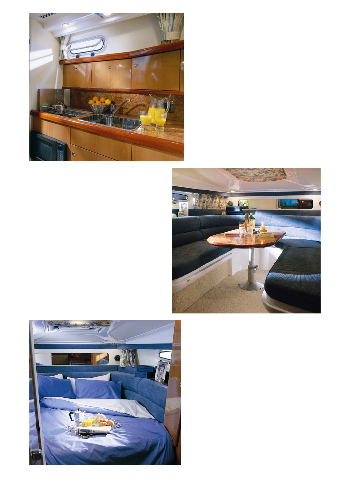
Galley
Saloon
Saloon Berth

Sealine International Ltd. (V1.1)
Page 4 of 61
Table of Contents
INTRODUCTION 1-4
TECHNICAL DATA 5
DECLARATION OF CONFORMITY 6
EU RECREATIONAL CRAFT DIRECTIVE EXPLANATION 7
OVER TO YOU & SAFETY 8 - 9
WARRANTY 10
FIREPROTECTION 11
ELECTRICAL SYSTEMS 12 - 16
BILGE PUMPS 17
ENGINES & ANCILLARY EQUIPMENT 18 - 21
STEERING SYSTEMS 22
FUEL SYSTEM 23
GAS SYSTEM 24
WATER SYSTEM 25
TOILET HOLDING & TANK SYSTEMS 26
EXTERIOR & INTERIOR CARE 27 - 28
LAYING UP & MAINTENANCE 29 - 30
Data Sheets and Diagrams
PRINCIPAL DIMENSIONS 31 - 32
DECKPLAN 33-34
EQUIPMENT LOCATION 35 - 36
SYSTEM CONTROL POINTS 37 - 38
GAS SYSTEM LAYOUT 39 - 40
SINGLE PETROL FUEL SYSTEM 41 - 42
TWIN PETROL FUEL SYSTEM 43 - 44
SINGLE DIESEL FUEL SYSTEM 45 - 46
TWIN DIESEL FUEL SYSTEM 47 - 48
BLACK & GREY WASTE DISPOSAL SYSTEM 49 - 50
MANUAL TRIM TABS OPERATION INSTRUCTIONS 51
WIRING DIAGRAMS – KEYPAGE 52
WIRING DIAGRAMS 53 - 59
NOTES 60-61
Sealine International Ltd. (V1.1)
Page 5 of 61
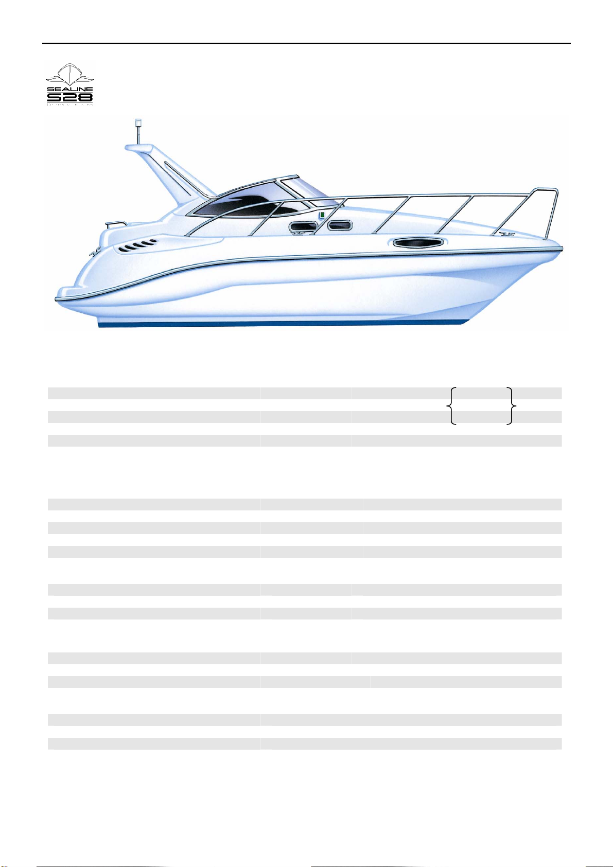
Declaration of Conformity - Technical Data
Dimensions Metric (Imperial) (to ISO 8666)
Length Overall 8.81 m (28’ 11”) LH = 8.82
Length at Waterline 6.78 m (22’ 3”)
Beam 3.02 m (9’ 11”) BH = 3.00
Air Height (above waterline inc. mast) 3.23 m (10’ 6”)
Draught (sterndrive down) Twin Engine 0.91 m (3’ 0”)
Draught (sterndrive down) Single Engine 1.09m (3’ 7”)
Capacity Metric (Imperial)
(to ISO 8666)
Fuel tank 1 x 414 L (91 Gal)
Water tank 170 L (37 Gal)
Waste Tank 94 L (20 Gal)
Grey Tank 61 L (13.5 Gal)
Gas Bottle 2 x 2.72 Kg ( 2 x 6lb.)
Weight Metric (Imperial) (to ISO 8666)
Dry weight approx. 4400 Kg (4.33 Tons)
Maximum persons 8 (8)
Maximum load 1600 Kg (3528 lb.)
(Including all optional additional equipment)
Power Metric (Imperial) (to ISO 8666)
Maximum rated engine power (Petrol) 176 kW x 2 (239 MHP x 2)
Maximum rated engine power (Diesel) 130 kW x 2 (177 MHP x 2)
Engine In board Stern Drive
Electrical
Batteries 3 x 95 ah 12 volts DC
Batteries (Twin & Electronic Engines) 1 x 95 ah Extra
Shore supply Single phase 50Hz 220-230v AC

Sealine International Ltd. (V1.1)
Page 6 of 61
Declaration of Conformity to EC Directive 94/25/EC
Sealine International Ltd. Whitehouse Road, Kidderminster, Worcs., DY10 1HT, GB
Type of Craft Pleasure Craft Notified Body RINA (#0474) Gruppo, Registro
Italiano Navale, Via Corsica,
Model Sealine S28
12-16128, Genova, Italy
Serial Number (HIN) GB-SIL28
Design Category
Hull
B
Monohull
I declare at my own and sole responsibility that the craft
mentioned above complies with all applicable essential
safety requirements in the way mentioned below and is in
conformity with the type for which the mentioned EC-type
examination certificate has been issued.
Issued By Simon Houlder
Construction Material Fibre Reinforced Plastic Design Manager
Signed
Deck Decked
EC Type Exam Cert. DIP-102197/2
Assessment Module B + c Date
08th March, 2002
Ref. Essential Safety
Requirement Standard or Documentation Reference
2. General Requirements
2.1. Hull Identification ISO 10087.95” Small craft-Hull Identification-Coding System
2.2. Builders Plate ISO 14945
2.3. Protection from Falling Overboard ISO 15085
2.4. Visibility from Main Steering Position ISO 11591
2.5. Owners Manual ISO 10240
3. Integrity and Structural Requirements
3.1. Structure RINA Rules - Sect. B Part I, III,
3.2. Stability and Freeboard ISO 12217
3.3. Buoyancy and Floatation ISO 12217
3.4. Openings in Hull, Deck and
Superstructure ISO 9093 - ISO 12216
3.5. Flooding ISO 11812 - ISO 12217 - ISO 12216 - ISO 8849
3.6. Manufacturers Recommended Load ISO 12217 – ISO 14946
3.7. Liferaft Stowage To be Developed
3.8. Escape ISO 9094 - ISO 12216
3.9. Anchoring, Mooring and Towing ISO 15084
4. Handling Characteristics ISO 8665 - RINA Rules - Sect. C. - Chap. 5
5. Installation Requirements
5.1. Engines and Engine Spaces
5.1.1. Inboard Engine ISO 28846 - ISO 9094 - ISO 7840 - ISO 10088 - ISO 10133 - ISO
11105 – ISO 16147
5.1.2. Ventilation ISO 11105
5.1.3. Exposed Parts Machinery (Safety) Regulations SI 1992/3073 and 1994/2063
5.2. Fuel System
5.2.1. General ISO 7840 - ISO 9094 - ISO 10088 - ISO 11105
5.2.2. Fuel Tanks ISO 10088 - ISO 11105
5.3. Electrical System ISO 10133 - ISO 13297 - ISO 8846 - ISO 8849 - ISO 9097 Electrical
Equipment SI 1994 / 3260 Electro magnetic compatibility SI 1992 /
2372 and 1994 / 3080
5.4. Steering System
5.4.1. General ISO 28848
5.5. Gas System ISO 10239 - Gas Appliances SI 1992/711
5.6. Fire Protection
5.6.1. General ISO 9094
5.6.2. Fire-fighting Equipment ISO 9094
5.7. Navigation Lights COLREG 1972 - CEVNI
5.8. Discharge Prevention ISO 8099
5.9. General Product Safety SI 1994 / 2328

Sealine International Ltd. (V1.1)
Page 7 of 61
EU Recreational Craft Directive Explanation
Module B
A notified body (R.I.N.A., 12, Via Corsica, Genoa 16128, Italy) to ascertain compliance with the essential health
and safety requirements of the EU Recreational Craft Directive (94/25/EC) has inspected a specimen of each
Sealine boat type.
Module C
The Declaration of Conformity declares that each boat is in conformity with the type as described in the EC type
examination certificate and lists the standards applied.
The design categories applicable are defined in the EU Recreational Craft Directive as:-
Category A “Ocean” : Craft designed for extended voyages where conditions experienced may exceed
wind force 8 (Beaufort Scale) and include significant wave heights of 4m, for vessels that
Are largely self-sufficient.
Category B “Offshore” : Craft designed for offshore voyages where conditions up to and including wind
force 8 and significant wave heights up to and including 4m may be experienced.
Category C “Inshore” : Craft designed for voyages in coastal waters, large bays, estuaries, lakes and
rivers, where conditions up to and including wind force 6 and significant wave heights up to
and including 2m may be experienced.
Category D “Sheltered Waters” : Craft designed for voyages on small lakes, rivers and canals, where
conditions up to and including wind force 4 and significant wave heights up to and including
0.5m may be experienced.
A maximum load = 1,600 Kg has been used for assessing stability and buoyancy comprising :-
Crew mass (at 75Kg per person) 600 Kg
fuel, fresh water, other fluids to maximum tank capacity 675 Kg
provisions and personal effects 200 Kg
optional additional equipment 055 Kg
inflatable liferaft(s) 030 Kg
other small craft carried aboard 040 Kg
Total Maximum Load 1600 Kg
This assessment has been made assuming that:-
the boat in the Light Craft Condition has a mass of 4,400 Kg
This boat has been given Design Category B with a crew limit of 8 in accordance with ISO 12217-1. This Category
is considered to be suitable for use in waves up to 4m significant height and a typical steady wind force of Beaufort
Force 8 or less, subject to :-
•the crew having suitable skill and experience
•satisfactory maintenance of the boat and equipment.
Users of this boat are advised that:-
•all crew should receive suitable training
•the boat should not carry more than the Maximum Load
•bilge water should be kept to a minimum
•stability is reduced by any weight added high up
•in rough weather, hatches, lockers and doorways should be closed to minimise risk of water ingress
•stability may be reduced when towing or lifting heavy weights using the crane
All Sealine Boats are being updated & improved constantly, therefore although every endeavour has been made to ensure the accuracy of the
information in this handbook, no liability can be accepted for any omissions or discrepancies that may occur

Sealine International Ltd. (V1.1)
Page 8 of 61
CAUTION
CAUTION
DANGER
WARNING
WARNING
Over To You
This manual has been compiled to help you gain maximum pleasure and safety from your vessel. We recommend
you read it carefully and familiarise yourself thoroughly with your new craft before use.
It contains details of:-
•The Craft
•The Equipment (fitted or supplied with)
•Systems
•Operating Information
•Maintenance
If this is your first craft, or you are changing to a type of craft you are not familiar with, we suggest that for the
comfort and safety of you and your crew, you gain some handling and operating experience before assuming
command. Your Sealine dealer, national sailing federation or yacht club will be pleased to put you in touch with
local sea schools or a qualified instructor.
Please retain this manual in a safe place to be handed over to future owners of this vessel.
Your Safety
Within this manual the following definitions are applied: -
DANGER - denotes an extreme intrinsic hazard exists which would result in high probability of death or irreparable
injury if proper precautions were not taken.
WARNING - denotes a hazard exists which can result in injury or death if proper precautions are not taken.
CAUTION - denotes a reminder of safety practices or direct attention to unsafe practices that could result in
personal injury or damage to the craft or components.
Regular Inspections
Attached to this handbook are instruction manuals for the components and appliances fitted to your boat. Ensure
you carry out inspections regularly in accordance with their instructions. In addition ensure you regularly check the
systems described in this handbook.
Boarding The Boat
Keep within the working deck guard rails when the boat is in motion. DO NOT use the bathing ladder when the
engines are running.
Engine and Transmission
Refer to the engine manual for operation, maintenance and winter storage of the engine.
Do not install or operate this craft with engines of rated power larger than shown on the technical data page.
Repairs
Contact a reputable boatyard or specialist installation manufacturer for the best advice and adapted parts or
materials for the repairs you can carry out by yourself. Professionals (See Warranty Conditions sections) should
preferably carry out large repairs on the hull or on the engine.
Modifications
Contact a reputable boatyard or specialist installation manufacturer about the possibilities of what you can do by
yourself. You could endanger your own safety and lose your warranty.
Lifting
Ensure a qualified crane or hoist operator with experience of lifting boats lifts the boat. Position straps in line with
the marks Sealine have fixed to the hull, and ensure the point of balance of the boat is between the straps. Use
spreaders and padding to ensure the hull is not pinched by the straps. DO NOT remain under or inside, the craft
when lifted.

Sealine International Ltd. (V1.1)
Page 9 of 61
CAUTION
WARNING
CAUTION
Your Safety
There is the potential to trap children’s fingers in the 170-degree storage hinge mechanism
As with all styles of flybridge motor yacht DO NOT motor your boat with the cockpit canopy side panels in place
and with the canopy aft panel stowed or with the accommodation access door open. This will cause the airflow
around the boat’s aft end to fill the accommodation with exhaust gasses.
Discharging
Before discharging, shut down engines and blowers.

Sealine International Ltd. (V1.1)
Page 10 of 61
Warranty Conditions
Dealer Quality Check on receipt of craft.
Sealine checks all new boats before shipment. Engines are lubricated throughout. The fresh water cooling system
(if any) is filled up with anti-freeze solution, or drained down depending on the time of year. (Drain plugs for the
engine’s raw water system are supplied separately within the boat). Some exterior fittings may have been
dismantled depending on the form of transportation, therefore on receiving the vessel from Sealine International
Ltd. the dealer/receiver undertakes to check the specification is complete and complies with the order. In addition
the boat requires a full sea trial to be carried out by the supplying dealer/receiver at which time the PDI (pre-
delivery inspection) must be completed and any necessary minor adjustments made. The dealer should set aside a
minimum of two days for the PDI and on completion is responsible for the insertion of the date of delivery to the
customer/owner on the Sealine Boat Owner Card. Failure to do so may invalidate the guarantee.
Guarantee
The Sealine International Ltd., guarantee applies for defects and flaws which may occur, despite normal use and
regular maintenance, for a period of 12 months from the date of delivery to the customer/owner. The guarantee
does not cover damage incurred in transit or the launching procedure. The guarantee does not cover docking or
transport expenses incurred in moving a vessel from, and returning it to, its home mooring or current venue to a
designated repair workshop. The individual guarantee, complaints and claims procedures specified by engine
manufacturers will apply to all engines and ancillary engine equipment. Other equipment installed in the vessel will
similarly be subject to the relevant manufacturer’s own complaints and claims procedure. The product is sold for
use as a pleasure craft and this warranty is restricted to use for these activities. The warranty is invalidated if the
craft is used for any form of commercial activities. Fair wear & tear is excluded. Evidence of maintenance being
carried out in accordance with the various manufacturers instructions must be made available at the time of making
a claim. The craft must be operated in accordance with the operating instructions contained in the Owners Manual.
Complaints and claims routines
All complaints or claims should be made to the supplying Sealine dealer, who will make a prompt report to Sealine
International Ltd. As far as possible the defect should be presented for inspection to the dealer or to someone
authorised by him. It is the responsibility of the dealer to find the most economic and competent repair service, so
that such repairs could be carried out by the dealer himself or by the nearest qualified marina or ship repair yard,
regarding the location of the vessel and restrictions concerning transport costs. The dealer must ensure that the
method of work and number of working hours involved are technically and economically justifiable. Spare parts
required for such work are to be acquired from Sealine unless the parties involved agree, in advance, to purchase
them from other sources.
Replaced parts, marked with the boat type and construction number, must be returned to Sealine within 30 days of
the completed repair work unless otherwise agreed by Sealine due to disproportional high transport costs.
A Guarantee Report Form is to be completed by the repairing agent and mailed to the Sealine dealer within two
weeks of the execution of the repair order. Provided that the repair work done is within the framework of the
provisions made in our guarantee certificate and that our complaints and claims procedures have been followed
Sealine International Ltd. will credit the dealer with proven expenses. British Courts of Law will decide any dispute
as to the above provisions.
Owner:
Address:
Post Code:
Name of Boat: Boat No:
Engine Type:
Purchased From: Date of Purchase:
Dealer Address:
Sealine International Ltd, Whitehouse Road, Kidderminster, Worcestershire DY10 1HT
Tel: 01562 749100 Fax: 01562 747709
Dealers
Seal

Sealine International Ltd. (V1.1)
Page 11 of 61
WARNING
Fire Protection
The boat is equipped with two fire extinguishers with a combined capacity of 10A/68B. They are in the following
locations;
Location: Aft end of saloon at centre of sliding door Fire Rating: 5A/34B
Location: Galley. Fire Rating: 5A/34B
See diagram in manual.
Your boat is equipped with an automatic fire extinguisher system, located in the engine compartment.
(Read the manufacturers information booklet provided). It can also be manually set-off by means of the pull toggle
at the helm station(s).
In the event of a fire, the heat sensitive automatic head in the engine compartment will release a fire-extinguishing
vapor, totally flooding the area.
The dashboard contains an indicator light for the automatic fire extinguishing system. The light will be ON when
the ignition is on and indicates that the system is ready. If the light goes out while the ignition is on, the system has
discharged.
WHEN DISCHARGE OCCURS, IMMEDIATELY SHUT DOWN ALL ENGINES, POWERED VENTILATION,
ELECTRICAL SYSTEMS, GAS SYSTEMS AND EXTINGUISH ALL SMOKING MATERIALS. DO NOT
IMMEDIATELY OPEN THE ENGINE COMPARTMENT!!! THIS FEEDS OXYGEN TO THE FIRE AND THE FIRE
COULD RE-START.
Wait at least fifteen (15) minutes before opening the engine compartment. This permits the fire extinguishing vapor
to ‘soak’ the compartment long enough for hot metals and fuels to cool. Have portable extinguishers at hand and
ready to use in case the fire reignites.
DO NOT inhale fumes or vapors caused by the fire.
It is the responsibility of the owner to:
•Have fire fighting equipment checked at intervals indicated on the equipment.
•Replace fire-fighting equipment, if expired or discharged, by devices of identical or greater fire fighting
capacity. Fixed fire extinguishing system must be suitable for compartment volume of
3.87 m3 (137) cu ft.
This is based on gross compartment volume less permanently installed tankage.
•Inform members of the crew about the location and operation of fire fighting equipment.
•Ensure that fire-fighting equipment is readily accessible when the boat is occupied.
•NEVER obstruct passageways to exits or hatches
•NEVER obstruct safety controls, e.g. fuel valves, gas valves, switches of the electrical system
•NEVER obstruct portable fire extinguishers stowed in lockers
•NEVER leave the craft unattended when cooking and/or heating appliances are in use.
•NEVER modify any of the crafts systems (especially electrical & fuel)
•NEVER fill any fuel tank when machinery is running or heating appliances are in use.
•NEVER smoke whilst handling fuel.
•Keep the bilges clean and check for fuel vapours at regular intervals.
•When replacing parts of the fire fighting installation only use matching components, which bear the same
designation or are equivalent in their technical and fire resistant capabilities.
•Combustible material shall not be stowed in the engine space. If non-combustible materials are stowed in the
engine space they shall be secured against falling into the machinery and shall cause no obstruction to access
in or from the space.

Sealine International Ltd. (V1.1)
Page 12 of 61
Electrical Systems
BATTERY CHARGING
General
The battery charger fitted is a 12V 40A device capable of keeping all the batteries in a good state of charge. When
the battery charger is not in use and the engines are running the engine alternators maintain the batteries and 12V
systems.
Main Panel Display
The 12V DC section of the AC/DC panel displays all the relevant information you need to keep your batteries in a
fully charged state; all that is required is a little understanding. By turning the main isolator switches to the "on"
position the voltage display will indicate the starboard/auxiliary battery voltage level. The port engine battery
voltage can be obtained from the engine voltmeter on the dashboard.
Next to the voltage display is the Amp Meter, which indicates (when the engine is not running), whether the 12V
system is charging (green) or discharging (red).
The idea of the display and battery charger is best-described using water as a medium. If you imagine your
batteries as a reservoir, and your battery charger as the water topping it up you will have a certain amount of
surplus when your reservoir is full (batteries fully charged). This surplus will be used up when your auxiliary circuits
are in use.
The battery charger is not an endless source of DC power, when you are using a lot of your auxiliary circuits the
display will fall into the red. This is when you are emptying your reservoir (discharging auxiliary batteries). This, in
normal use, will be topped up when you are using less auxiliary circuits (display in the green).
Prolonged use with the display in the red will lead to flat batteries. When shore power is not available, your
starboard engine will take care of auxiliary battery charging. To recharge these batteries will take some time
provided that auxiliary circuits are used to a minimum. Should you discharge your batteries to an extent that you
are unable to start your starboard engine, firstly start the port engine then press and hold the battery link switch to
start the starboard engine.
Engine Charging System
The 12V DC system has one (two for electronic engine) battery for starting the port engine and three (two for
electronic engine) batteries for starting the starboard engine and running auxiliary equipment.
The port engine charges its own batteries.
The starboard engine charges the starboard/ auxiliary batteries.
The port and starboard battery banks are independent. There is no link for charging.
Battery Link Solenoid
Should one of your battery banks become discharged and you are unable to start
one of the engines, you should first start whichever engine has good batteries.
Press and hold the battery link push button and at the same time start the other engine.
BATTERIES
General
In order to supply auxiliary circuits, ignition, starter motor etc., you need an efficient reliable constant source of
energy. To achieve this a little understanding and care is needed. The battery is not an inert object, it leads a highly
interesting electrochemical life.
Battery Self Discharge
Any charged battery left standing, gradually loses its charge, this is unavoidable. The average rate of discharge is
about 1% of the capacity per week. This can be more if batteries are not cleaned. Taking this into consideration, if
you are leaving your boat for a long time, such as winterising, some maintenance is required.

Sealine International Ltd. (V1.1)
Page 13 of 61
WARNING
Electrical Systems
Service Life
The service life of your batteries is directly linked to the maintenance and treatment received. Every time a battery
is discharged below 60% of its capacity its service life is reduced.
Recharging
Under normal conditions the battery charger will take care of battery recharging. Should your batteries become
discharged because you are unable to use shore support and engines have not been used, a little consideration
will have to be given to recharging.
An interesting point here is that a battery will only recharge at approximately 10% of its total capacity i.e. if you
have used 20A of power for 4 hours a 100AH battery will be 80% discharged. To replace the charge the battery
charger will take 8 hours. That is if you are careful not to use too much power during this time as the shore support
will be using a percentage of its output recharging batteries.
Boost charging will recover discharged batteries quicker, but you are strongly advised not to use this method in the
confines of the engine compartment or even on your boat.
Battery Terminals
Acid corrosion is far more serious than generally realised. It can cause sluggish starter operation and create
charging problems. The battery terminals should be clean and coated with suitable acid free and acid proof grease.
Always connect the positive cable first, negative last. Conversely, remove the negative cable first.
Maintenance
Do not smoke, produce sparks or work with a naked flame near a battery, this may cause an explosion. Always
wash hands thoroughly after handling batteries. Do not place tools or equipment on the battery as this could cause
a short circuit and explosion.
Batteries Taken Out Of Service
Should you take your battery out of service, such as winterising, it must be stored in a cool dry place and be
recharged every 1 to 2 months.
Bow thruster and generator starting batteries (when fitted) must also be included in the maintenance schedule.
MAIN POWER PANEL
General
This is mounted inside the cabin. It is split into two sections 220v AC main power to the left and 12v DC battery
power to the right. (Refer to wiring diagram Sht. 6)
AC Section
The 220V-230V AC section of the main power panel has a main switch which is a Residual Current Device
(R.C.D.). This switch has two functions; firstly it is the main switch, which turns the AC systems on;
ON (Up) OFF (Down)
Secondly it will trip itself off if there is a fault within the AC system.
The R.C.D. is also fitted with a test button, which should be pressed weekly with the system on to check that the
system is working correctly.
In the AC section there are also circuit breakers/switches for various items such as battery charger, water heater,
sockets, etc., should one of these become overloaded it will trip to the OFF position.
ON (Down) OFF (Up).

Sealine International Ltd. (V1.1)
Page 14 of 61
WARNING
WARNING
WARNING
CAUTION
Electrical Systems
Polarity Check
The polarity check should be used when connecting to shore supply to ensure that the source is correctly installed
and will not cause any damage to the boats electrical system.
1. Connect shore power cable
2. Ensure that the centre and right hand LEDs are illuminated brightly
3. Switch to shore power ONLY if polarity is correct.
DO NOT switch to shore power if the polarity is incorrect.
Consult your dealer or an electrician before using the AC system, if the 220V R.C.D. switch fails to trip to the OFF
position when tested whilst connected to shore supply.
DC System
The 12V DC system section of the main panel has similar rows of circuit breaker switches to those in the AC
section. These all operate in the same manner.
Should a particular breaker repeatedly require setting then there is obviously a fault. Consult your dealer or an
electrician.
Helm Panel
The helm panel is made up of switches. These require the relevant circuit breaker\switches on the main panel to be
in the ON position before they will operate, i.e. wipers, horn, bilge, blower, etc.
1. To prevent personal injury, always disconnect power source before servicing commences.
2. To prevent personal injury, never use 240v AC power tools while working in water or a wet environment.
3. Never modify the electrical installations and relevant diagrams unless carried out by a qualified marine
electrician.
4. Never alter or modify the rated current of the over-current protective devices.
Sealine International Ltd. (V1.1)
Page 15 of 61
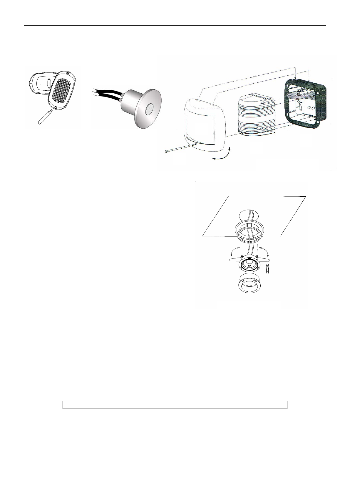
Cabin and Deck Lights
There are different types of cabin lights fitted to your Sealine. Should any of the lighting circuits become overloaded
they are all protected by circuit breakers on the main power panel. The following diagrams show how to replace the
lamps. The deck lights have a 100,000 hour L.E.D.life. The deck bulbs can not be changed, the whole unit needs
to be changed.
Navigation Lights
The appropriate switch on the main panel operates the
navigation Lights. If one of your navigation light bulbs need
replacing, simply remove the screw, which retains the lens,
and pull the cover off. The lamps fitted in the navigation lights
vary slightly depending on where they are fitted,
i.e. Stern light 10W, Port, Stbd and steaming navigation lights
25W. The anchor light lens simply twists off and uses a
10W-festoon type lamp.
To open the navigation light follow diagram, turn screw A loose
and pull It until blocked. Remove housing B by pulling the
bottom part. Pull Lens C straight out to change bulb D.
.
Bow Thruster (if fitted)
The bow thruster battery and battery master switch are located under the floor in the forward cabin. To operate the
bow thruster, ensure that the master switch is ON.
Moving the joystick in the required direction, port or starboard will move the bow as required. A delay of
approximately 1½ seconds is built into the system when changing rapidly from one direction to another. This is to
enable the motor and hence the propeller to stop before changing direction. Only use the bow thruster with engines
running. Always switch off the master switch before leaving the boat.
NOTE: Never run the bow thruster continuously for a long period of time.
As a guide the maximum “on” time must not exceed 50% per 10-minute period. DO NOT exceed a running period
of 5 min. continuously.
Engine Room Light Deck Light
Navigation Light
A
B
C D
Cabin Light

Sealine International Ltd. (V1.1)
Page 16 of 61
WARNING
Cabin and Deck Lights
Electric Windlass
The electric windlass is operated from the foredeck or from either helm panel. The on/off switch on the main power
panel isolates all windlass switches. This will prevent the windlass from accidentally being operated by someone
standing on the foredeck etc. A great deal of power is required to operate the electric windlass, it is therefore
advised that you have your starboard engine running to prevent unnecessary drain on your batteries. It is good
seamanship to assist the windlass by motoring very slowly towards the anchor during recovery. Should the
windlass fail to operate check the circuit breaker mounted on the battery switch panel.
Please read the manufacturers operating and maintenance information booklet provided.
Windlasses are virtually maintenance free; only occasional inspection and greasing of moving parts is necessary.
The solenoids, which operate the winch, should occasionally have their electrical connections checked for
tightness. They should also be sprayed with a suitable moisture repellent spray.
Modifications to Electrical Circuits
Owners should not add components to the electrical circuits of the boat without reference to the current audit. This
is available from authorised Sealine dealers.

Sealine International Ltd. (V1.1)
Page 17 of 61
Bilge Pumps
Bilge Pumps/Float Switches
All bilge pumps fitted to your Sealine have float switches. In the case of the forward and aft bilge pumps this is for
safety reasons. Should a leak occur when the vessel is unattended these float switches have a permanent source
of power from the push to reset circuit breakers fitted in the battery isolation panel in the cockpit locker (see System
Control Points Diagram).
In the interest of safety, the operation of the float switches on these pumps should be checked from time to time to
ensure that they operate smoothly. An occasional check should be made on the condition of the bilge pump
strainer; this should be kept clear of debris and other foreign matter.
The pump itself is not affected by freezing temperatures.
The instructions below will help you obtain the maximum output and life from your pump: -
Symptom Possible Cause Cure
Repeatedly
tripping
circuit
breaker
Faulty wiring CONSULT QUALIFIED ELECTRICIAN
Reduced
Flow Blocked
strainer Clean out side of strainer and clean debris from around impeller
Discharge line
blocked with
trash
Clean out hose by back flushing
Low battery
voltage Check battery condition and charge if necessary
Kinked
discharge hose Repair or replace hose
No water
pumped Wire
connections Make sure wire connections are not corroded. Visual check is not enough - a slight pull on each wire should
tell if the wires are still joined. Check to be sure no wire joints are hanging down into the water
Tripped
breaker Reset circuit breaker. If breaker still blows, check impeller through inlet opening to be sure it is not jammed
or stuck with debris
Float switch
failure Lift end of float switch up - if pump runs, switch is OK. If pump does not run, turn Manual Switch to ON
position - if pump runs, automatic switch has failed
Pump won’t
shut off
Something
under float Clean under float to make sure that debris is not holding the float up
Stuck float Check to see that the float is loose and free of gummy oil. If float action appears sluggish and/or the float
does not move freely, intermittent or sporadic operation of the pump may occur. This condition is usually the
result of oil and/or dirt accumulating in and around the movable parts of the switch. To correct try soaking
the entire switch in the bilge cleaner for ten minutes agitating several times and checking for smooth and
free operation of the float. Repeat if necessary.
Switch
mounted to low If the pump is sucking air and the automatic switch has not reached the OFF position, then the switch may
be mounted too low for the pump and should be re-installed higher than the pump base.
Shower Sump
The only maintenance required on the sump system is to drain the unit during the winter months when not in use.
To drain; disconnect and drain all lines to the unit. Remove hold down screws and empty the unit. In some
installations it may be impossible to completely drain the system. As a result of this it is recommended that non-
toxic RV/Marine antifreeze be added to the shower drain and circulated throughout the system. Periodic cleaning of
the filter for improved performance is recommended. Ensure the cover gasket is in place when reinstalling the filter
and cover.
Problems
Pump will not turn on: - Pump will not turn off: -
Line is blocked Float switch is jammed in the ON position
Line is broken Air is trapped in the pump
No power to the pump Output pipe is blocked/restricted
Circuit breaker tripped
System improperly wired
Air is trapped in the box - vent box
Pump output is low: -
System is incorrectly wired
Outlet is blocked/restricted

Sealine International Ltd. (V1.1)
Page 18 of 61
WARNING
Engines and Ancillary Equipment
General
The engines and stern drive fitted in your Sealine are designed for running in a hostile environment. Engine
owner’s manuals should be studied thoroughly. It is recommended that the manufacturer’s service schedule be
followed due to the specialised nature of the engines.
Running In
Your new engines and stern drives must be run in. Care should be taken during the first 20 hours not to operate
engines on full load. Details of this can be found in the engine owner’s manual. After running in, the engines must
be serviced or the manufacturers warranty may be become invalid. It is good practice even after the running in
period not to use the engines at peak revolutions for sustained periods.
Starting Engines
Before starting the engines check the engine and power steering oil levels, the engine’s fresh water coolant level
(not when hot) and the cleanliness of seawater filters (if fitted). When those few checks have been carried out
lower the drives, turn the fuel tap to the “on” position then run the engine blower for a minimum of 4 minutes before
cranking. On petrol engines it may be necessary to use the throttle. To do this push in the button situated in the
base of the control lever. This will put the lever in the “Throttle Only” position. If necessary use the battery link
switch to provide extra power for starting. The battery link switch can be found on the helm panel and should be
held down during engine starting. If the engine will not crank, check that the neutral gear has been selected.
The engine compartment bilge blower must be run for a minimum of 4 minutes prior to the engine start up. This will
remove any explosive vapours such as petrol and gas.
1. Warning
2. Run engine compartment blower for at least 4 min.
3. Start engine
Neutral Safety Switch
Every control system has a safety switch incorporated into it. This device prevents the engine from being started
whilst the gearshift lever is in any other than the neutral position.
If the engine will not crank over, slight movement of the gearshift lever may be necessary to locate the neutral
position and disengage the safety cut out switch.
Control or cable adjustments are required to correct the above situation should it persist.
Diesel Alarm
The diesel alarm monitors engine temperature, alternator and oil pressure. Should the alarm keep sounding or
sound during use, stop the engine and investigate the problem, if in doubt refer to the engine manufacturer's
manual. There is a manual test switch for the alarm on the instrument should you wish to check that the alarm is
functioning correctly.
NOTE: This alarm does not monitor the gearbox oil levels.
Engine Instrumentation
Instruments will vary according to the different engine manufacturers. The normal operating condition for each
individual gauge should be noted from the engine handbook. Generally the following instruments are fitted as
standard:
Tachometer
The tachometer gives an accurate indication of engine speed in revolutions per minute (rpm). It is also essential for
the ‘running in’ period and economical cruising.

Sealine International Ltd. (V1.1)
Page 19 of 61
CAUTION
Engines and Ancillary Equipment
Oil Pressure Gauge
This indicates the engine oil pressure. Should low oil pressure be noted, switch off the engine and check the engine
oil level. If this is correct seek professional advice - serious damage may otherwise occur.
Temperature Gauge
This indicates the coolant water temperature. If, after running the engine for a period of time, a high reading is
evident, switch off the engine and check the raw water coolant system.
If the engine is fitted with a fresh water system the coolant level should be checked remembering that the coolant
becomes pressurised when heated and the cap must be removed with great care. Should this level be low, fill the
system, run the engine for a short period of time and then check the system for leaks.
Volt Meter
This indicates the relevant engine battery condition. The normal reading with the ignition switched on should be 11-
12 volts. When the engines are running at or above fast idle the reading should increase to 13-14V as the
alternator charges the battery banks.
Fuel Gauge
This indicates the amount of fuel onboard. The most accurate reading will be given when the boat is static.
Engine Hour Meter
This is used for recording engine operating times and obtaining maintenance and cruising information.
Ignition/Starter Switch
The ignition switch (petrol’s) turns on power to the engine and instrumentation and starts the engine when turned
fully. The starter switch (diesels) turns on power to the engine and instrumentation and also provides a heater
position for diesel engine installations and a stop position for activating the fuel stop solenoid
Throttle and Gear Controls
The gear/throttle levers, which operate the engine, consist of three components per engine, the mechanism and
two throttle cables. On single lever controls, when only throttle is needed, it is necessary to press in the button on
the lower part of the control lever. This will put the control lever in “throttle only” mode.
Power Trim
The stern drives can be trimmed using the appropriate switches on the dash panel, this in turn will raise or lower
the stern drive whichever you require. When planning, greater economy can be achieved by trimming the stern
drives. This will require a little practice, but you will soon learn which is the best position. Trim positions will vary,
depending on sea conditions and loading of the boat.
DO NOT under any circumstance raise the stern drive fully when the engine is running as serious damage may
result.
NOTE: Frequent checks of power trim pump oil levels should be made.
Trim Tabs
Trim tabs, if fitted, provide maximum control in all water and load conditions. When used properly they will improve
performance and efficiency. Planing speed can be achieved quickly and more economically if the trim tabs are fully
extended. Once the boat has achieved planing speed the trim tab should be raised allowing the nose to rise,
therefore reducing the amount of hull in the water.
Should the boat list due to bad weight distribution or weather conditions it can be counteracted using the trim tabs.
A little practice will perfect trim tab operation and their use will become natural. The trim tab gauge reflects the
relative position of the trim tab to the hull.
Trim tab damage may result if the tabs are fully extended (down) at more than 20 Knots.
Propellers
The propellers fitted on your Sealine will be matched to the engine installation to gain the best compromise of
performance and economy. Pitch and diameter or code size as with a duo prop, is stamped on the propellers.
If your propeller becomes damaged, slight nicks and bends can easily be repaired. Should the damage be more
serious it will be necessary to seek professional repairs.

Sealine International Ltd. (V1.1)
Page 20 of 61
WARNING
WARNING
Engines and Ancillary Equipment
Propeller Installation
IMPORTANT: Correct rotation propeller MUST match direction of rotation of propeller shaft.
Be sure that the remote control is in neutral position and ignition key is removed from switch prior to installing the
propeller.
Place a block of wood between the anti-ventilation plate and propeller to protect hands from propeller blades and to
prevent the propeller from turning when tightening propeller nut.
Stern Drives
IMPORTANT: Installation is correct when at least 2 threads of propeller shaft are exposed through the
propeller nut after applying the torque required.
Install the propeller with attaching hardware as shown. Tighten nut until a minimum of 55lb. ft. (75 N-m) is attained;
then, continue to tighten until the 3 tabs on the tab washer align with the grooves on the spline washer. Bend the 3
tabs down into the grooves.
a - Apply lubricant on splines of propeller shaft
b - Forward thrust hub
c - Propeller
d - Continuity/spline washer
e - Tab washer
f - Locknut
Volvo Single Prop.
Volvo Duo Prop.
Duo prop has two counter rotating propellers and is claimed to give up to 15% greater thrust. This means better
acceleration and higher top speed.
NOTE: Small nicks or bends in the propeller blades will greatly reduce performance.
Table of contents
Other SEALINE Boat manuals


