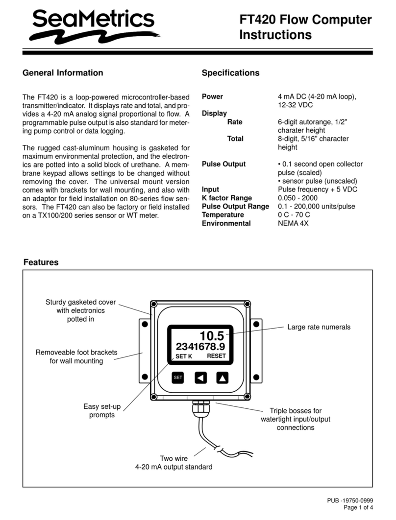
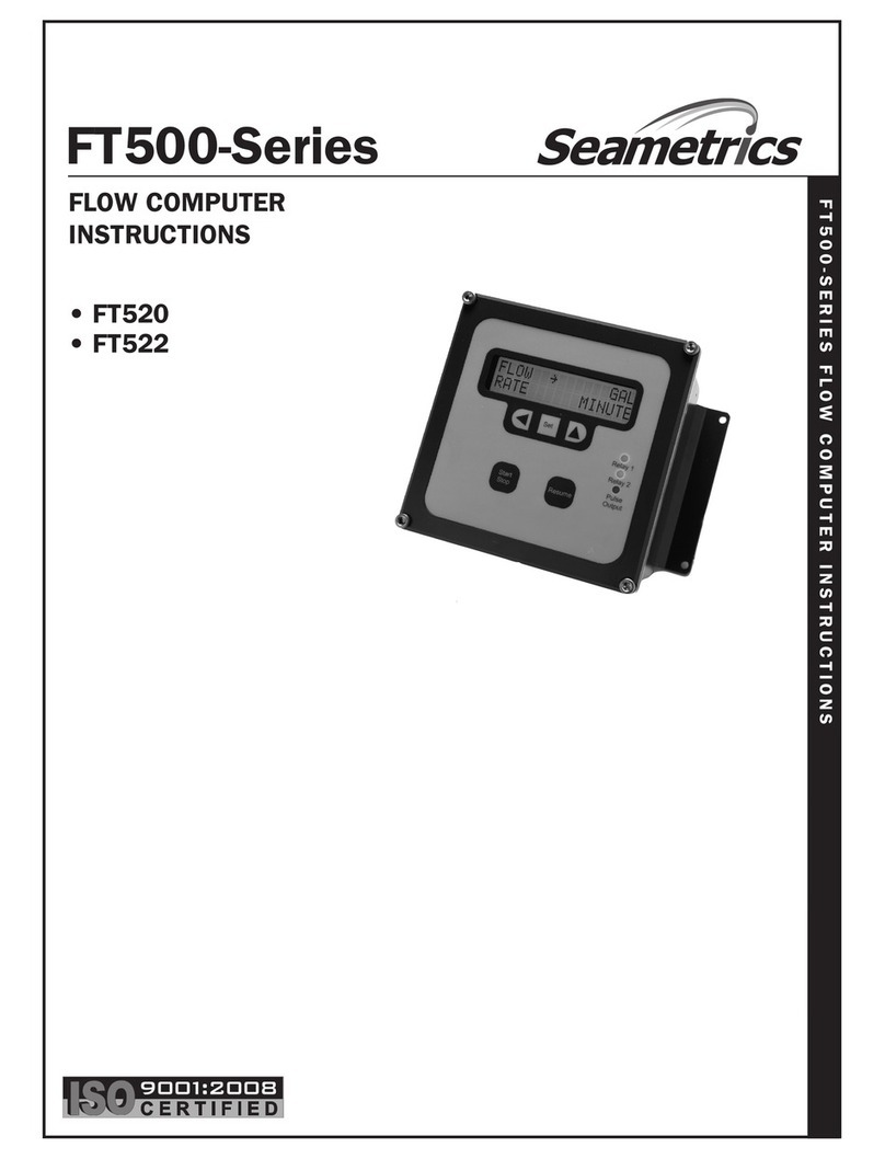
Seametrics FT500 Series User manual

PUB -19501-0796
Page 1 of 4
SpecificationsGeneral Information
The FT500 flow computer provides rate and total flow
display, as well as additional output features. It is de-
signed for use with SeaMetrics meters, as well as many
other meters which provide a pulse-type output. Flow
rate and total are alternately shown, in user-selectable
units, on a large alphanumeric LCD display. The accu-
mulated total can be reset with a series of keystrokes.
High-flow and low-flow alarm setpoints are a standard
feature. The relay outputs of these alarms can be used
to operate a warning device such as an autodialer, or to
shut off critical equipment, such as a pump. The stan-
dard programmable pulse output is useful for metering
pump proportional feed or telemetry.
An optional analog output (0-10 V or 4-20 mA) is easily
field-calibrated. Zero and span are front-panel pro-
grammed in flow units.
The FT500 comes in a weathertight enclosure with a
hinged clear cover over the membrane front panel. Ter-
minal acccess is simplified by a separate cover. Both
12 VDC and 115 VAC versions are available.
Power 115 VAC or 12-16 VDC
(optional), 4 watts max
Temperature 32°- 130°F (0°- 55°C)
Humidity 85% non-condensing relative
Enclosure Polystyrene (NEMA 4X with
conduit connection option)
Outputs Two form C SPDT relay 120
VAC 5 A max.
Max Pulse Output 100 mA at 60 VDC (100ms)
Memory Type Battery-backed RAM
(10 year retention)
Sensor Power 12-16 VDC, 50 mA
Totalizer 8 digit (resettable)
Rate Display 5 digit (0-99999)
Engineering Units 1000 gal., cubic mtr., cubic ft.,
Imp. gal., gal., liters, 0.1 gal.,
fluid oz., cubic in., and mm.
Analog Output Optional 0-10 VDC or 4-20
mA 8-bit resolution, 500 ohm
max load
Sensor Input Max. current 25 mA at 12
VDC, Max. frequency 500 hz
Shipping Weight 5 lbs.
FT500 Flow Computer
Instructions
Terminal cover
removes for
easy access
High/Low flow
alarm indicators
(correspond to relays) Automatic recalculation
of units
Large, alphanumeric
display
Hinged door cover
for protection
Press to select
displayed function
Decrease
setting value
Back to
previous display
Forward to
next display
Increase setting value
FT500
FLOW COMPUTER

Installation
Caution: The FT500 like any
other electronic control can
suffer failure. If failure of the
unit could result in personal
injury or property damage,
safeguards must be installed to prevent such
injury or damage.
!
!
Caution: Always disconnect
power to the unit before open-
ing the terminal cover. Do not
reconnect power until all con-
nections have been made and
the terminal cover has been replaced.
Mounting. The FT500 enclosure can be mounted to
any secure surface with three screws. Drive the center
screw first, leaving the head protruding slightly from the
surface. Locate the center mounting lug on the back of
the control, and slide it over the shaft of the screw. Re-
move the terminal cover to expose the other two holes.
Insert screws through them and tighten.
Connections.
All connections are made with the lower terminal cover
removed. Follow the connection diagram or the termi-
nal markings on the board(s) to make connections.
Connect the meter first, then the outputs, and the power
last. Leave the other end of any outputs disconnected
until output programming is completed, since they may
activate unexpectedly and unpredictably when the un-
programmed unit is powered up.
Meter Input. Note that either powered (3-wire, typically
with Hall-effect sensors) or unpowered (2-wire, reed
switch) meters can be connected by following the con-
nections diagram. The strain relief provided with the
meter can be used with most types of meter cable. If
the FT500 is equipped with a SeaMetrics 3-pin connec-
tor, a SeaMetrics meter with mating connector can be
plugged in with no additional connection.
Pulse Output. This open-collector transistor output is
useful for proportional feed using an electronic metering
pump, for telemetry, or for remote indication. Follow the
diagram, noting the proper polarity. Cables are avail-
able from SeaMetrics for specific metering pumps, if re-
quired.
Flow Alarm Outputs. If you are using the high-flow or
low-flow alarms, connect to the K1 or K2 relay termi-
nals, following the diagram. The relays energize when
their respective flow rate setpoints are reached. You
can use the normally-open contacts (they close when
thesetpointisreached)ornormally-closedcontacts(they
open when the setpoint is reached).
Analog Output. If the optional analog board has been
specified, it will be present on the right hand side of the
terminal compartment. There are two sets of terminals
on the board, one pair for 4-20 mA and one pair for 0-10
V. The board is factory-configured for one output or the
other, and is marked accordingly in the appropriate box.
Connect following the diagram. Note that the standard
internal power source for the 4-20 mA current loop will
drive up to a 500 Ohms load. If your load exceeds this
amount, it is necessary to connect an external power
source in series to drive it.
Programming
Run/Program Key. Pressing this key switches back
and forth between RUN and PROGRAM. Normal op-
erationisinRUN. ChangestosettingsaremadeinPRO-
GRAM.
Arrow Keys. Either key may be used at any time. The
forward key brings up the next display, and the back
arrow returns to the last one.
Increase/Decrease (▲/ ) Keys. Any setting which is
being displayed is increased by the (▲) key and de-
creased by the ( ) key. The longer a key is held down,
the faster the setting changes. If the desired setting is
overshot, use the other key to go back to it.
Select Key (*). When this key is pressed it selects the
option displayed. For example, pressing this key when
the display reads “ * for OUTPUT change” brings up the
first of the output settings.
!
Caution: When the control is
powered up, relay or analog
outputs may be present. If this
could be a hazard, wait to make
external connections until pro-
gramming is complete.
2 of 4
▲
▲

Displays
Connections
GND
+12VDC
POWER SUPPLY INPUT
- (BLACK)
+ (RED)
GND (BLACK)
INPUT SIGNAL (WHITE)
+12VDC {RED}
}
}
}
TO FLOW METER
SCALED OUTPUT PULSE
TO METERING PUMP
N.O.
COMMON
N.C.
N.O.
COMMON
N.C.
K1 RELAY
LOW FLOW
ALARM
{
{
K2 RELAY
HIGH FLOW
ALARM
FOR REED SWITCH TYPE METERS
USE GND AND INPUT TERMINALS ONLY
CHART RECORDER -
CHART RECORDER +
CHART RECORDER -
CHART RECORDER +
0-10 VDC
OUTPUT 4-20mA
OUTPUT
NOTE: OUTPUT TYPE IS FACTORY SET
CONSULT FACTORY TO CHANGE
N.O.
COMMON
N.C.
N.O.
COMMON
N.C.
K1 RELAY
LOW FLOW
ALARM
{
{
{
{
{
K2 RELAY
HIGH FLOW
ALARM
110 VAC
INPUT NEUTRAL
HOT
GND
GND
INPUT
+12 VDC
GND
+ OUTPUT
TO FLOW METER
FOR REED SWITCH TYPE METERS
USE INPUT AND GND TERMINALS ONLY
SCALED OUTPUT PULSE
TO METERING PUMP
Optional 12-18 VDC Power
Standard 110 VAC Power
Optional Analog Output
RATE 1234 GPM
TOTAL 12345678 GAL
RESETS TOTAL
AND UPDATES UNITS
UNITS = GALLONS/MIN
Dsply Contrast = 14
for 4-20ma change
K Factor 1.000 UPDATE TIME=1000ms
HI ALM 195 GPM
LO ALM 97 GPM
10 Gals. / Pulse
4mA 0 GPM
20mA 195 GPM
RUN
PROGRAM
for METER change for UPDATE change
When in PROGRAM the “ ” and “ ”
keys add or subtract from the
value displayed
The 4-20ma display only appears if
the optional AC10 board is installed.
for OUTPUT change
TO RESET TOTAL
Note:
Note:
3 of 4

Total. Theaccumulated total isshown up to99,999,999
units. To reset to zero, press the select (*) key while
total is showing on the display. Then press ( ) as in-
structed to reset.
High/Low Alarm. Whenever flow exceeds the “HI”
setpoint, an up arrow appears on the Rate display and
the appropriate relay energizes. When flow drops be-
low the “LO” setppoint, a down arrow appears and the
matching relay energizes.
Analog Output. If this option is installed, the 4-20 mA
or 0-10 V signal varies continuously with the flow, be-
tween the two programmed endpoints.
Maintenance and Repair
Repair. The circuit boards of the FT500 are not de-
signed for field repair. If the unit fails for any reason
other than a blown fuse or lack of power, it is generally
advisable to contact the distributor through whom the
unit was purchased. The distributor or factory can gen-
erally repair and return the unit quickly, for a flat fee re-
pair. Any returns to SeaMetrics must be accompanied
by an RMA (returned material authorization) number.
FrontPanelRemoval. Thefrontpanelmustberemoved
to change a fuse, or to add an analog or other acces-
sory board. To remove it, open the front (clear) cover.
Remove the two screws on the left side and the two hex
standoffs on the right. Gently loosen the panel and lift it
out. The main (display) board is attached and will come
out with the panel. This exposes the fuses, which are
on the power supply board.
Fuses. The power supply and the pulse output circuit
have fuse protection. The two fuses are on the power
supply board. If it is necessary to replace a fuse, use a
1/2AmpAGC, readily available from auto parts or elec-
tronic supply stores.
Units Setting. This determines which flow rate and
volume units will be displayed. Pressing the ▲key
changestolargerunits,andpressingthe keychanges
to smaller ones. The largest unit is 1,000 gallons, and
the smallest is milliliters.
Meter Setting. Select this setting to set the
K-factor
.
This is the number of pulses per gallon which the meter
produces. For SeaMetrics meters, this number is either
on a tag (80-Series IP, S-Series, M-Series, WTTurbine)
or in a chart for the particular pipe size (100/200-Series
IP). For other meters, it may be given as a meter factor
or as a “pulse rate”, in pulses per gallon.
Update Setting. This determines the interval at which
the flow rate display is updated. It can be set anywhere
fromone to 2,000milliseconds. Typically 1,000 to2,000
is the best range. Longer intervals stabilize the display
byaveragingmorepulses,butalsodecrease the respon-
siveness to fast fluctuations. This setting applies to rate
only, and does not effect total.
Output Settings. There are three output settings:
LO ALARM is the low-flow setpoint. When flow drops
below this setting, the LO relay energizes and a down
arrow appears in the Rate display.
HIALARMis the high-flowsetpoint. When flow exceeds
this setting, the HI relay energizes and an up arrow ap-
pears in the Rate display.
PULSEOUTPUT controls the ratio, in units perpulse, of
the open-collector transistor pulse output.
Analog Settings. This choice only appears if the op-
tionalAC10 analog output board has been installed, ei-
ther in the factory or the field. The two settings are:
4 mA = ( set in flow rate units, for example, 0 GPM)
20 mA = (again, set in units, for example, 200 GPM)
Display Contrast Setting. A number between 1 and
14 controls the contrast of the LCD display. The best
setting depends on location (high or low on the wall)
and lighting (indoor or outdoor) but typically a number
between 10 and 14 gives the best results.
Operation
Rate Display. Flow rate is displayed in the selected
units. If units are changed at any point, all of the set-
tings will recalculate themselves into the new units. To-
tal will remain in the previous units, however, until it is
reset to zero.
20419 80thAve. So., Kent WA. 98032 USA
Phone: 206-872-0284 Fax: 206-872-0285
4 of 4
▲▲
Other manuals for FT500 Series
1
Other Seametrics Desktop manuals
