Seamless Group Inteligain SG800 User manual
SG800 Signal Amplifier Installation Manual Page 1 of 2
Copyright 2002, Seamless Group, Inc., All rights reserved. Made in North America
Note: Before installing the SG800 Signal Amplifier, please read the entire contents of this manual.
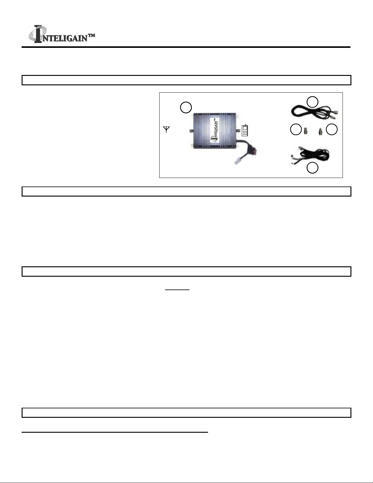
Parts List
Item Qty Description
1 1 SG800 InteligainTM Signal Amplifier
2 1 1.5 Meter (59”) RF Cable
3 1 2 Meter (78”) DC Power Cable
4 1 Connector Adapter FME Female to
TNC Male
5 1 Connector Adapter FME Male to TNC
Male
3A
Fuse
PHONEANTENNA
12
3
5 4
3A
Fuse
PHONEANTENNA
12
3
5 4
Tools and Other Materials Required
Item Description
1 Electric drill (as required for signal amplifier mounting holes)
2 Screw driver
3 Qty 4 screws (length and type as required for signal amplifier mounting)
4 Wire cutters / strippers
5 Qty 2 wire connection insulators or insulating material (as required for DC power cable connection to 12V DC system)
WARNINGS!
∇ Directly wired vehicle antennae, mounted a minimum distance of 50 cm (19.5”) away from any person, are
recommended.
∇ Mounting a signal amplifier in the engine cavity or on the underside of the vehicle will void the manufacturer’s
warranty.
∇ Subjecting the amplifier to voltages greater than 30 Volts DC will damage the amplifier and void the manufacturers
warranty.
∇ Any vehicle with an electrical system of greater than 30 Volts DC should use a step-down voltage regulator to bring
the voltage within the DC operating power range of the amplifier (10 to 30V dc).
∇ Under no circumstances should the amplifier be powered up without a properly connected 50 ohm 800 MHz
cellular antenna or the amplifier may be damaged and the manufacturer’ warranty will be void.
∇ An antenna of not more than 5dBd gain shall be used with the amplifier or the manufacturer’s warranty will be void.
∇ Use of cellular amplifiers with antennae of higher gains is in violation of FCC regulations for which the offender will
be fully liable.
It is recommended that only certified automotive installation technicians install this product in a
vehicle. Installation by any other person is at the risk of the vehicle owner and operator.
Installation
Selecting a Suitable Location To Mount The Signal Amplifier
Locate a suitable place to mount and conceal the signal amplifier. Suggested mounting locations include: under the dashboard,
under a seat, or in the trunk. For peak performance the signal amplifier should be mounted as close to the phone handset as
SG800 Signal Amplifier Installation Manual Page 2 of 2
Copyright 2002, Seamless Group, Inc., All rights reserved. Made in North America
possible. The amplifier’s location should be easily accessible and mounted away from moving parts, as well as excessive heat
and moisture.
Installation Cautions
∇ Use caution to avoid drilling through or near fuel lines or fuel tanks; brake lines; or electrical wiring.
∇ Do not mount the signal amplifier or its associated wiring in a location that may interfere with the safe operation of
the vehicle.
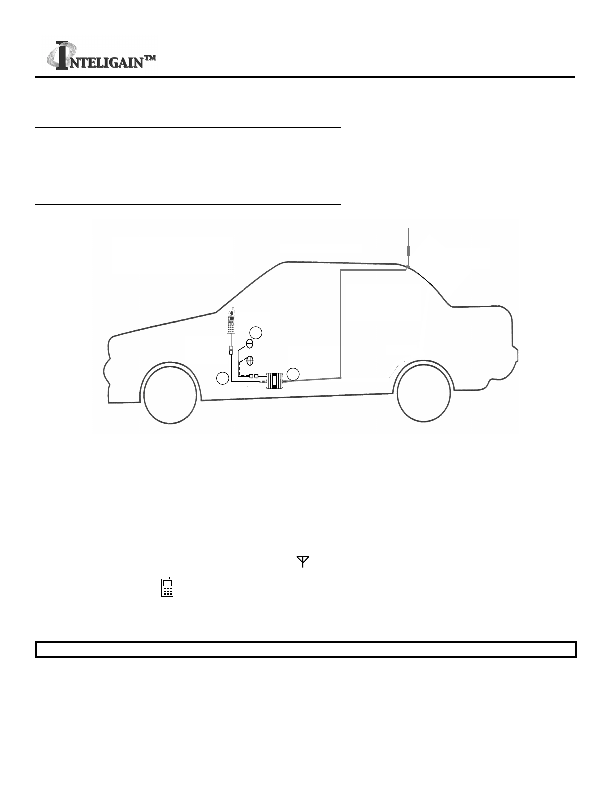
Installation Of The Signal Amplifier
Signal Amplifier
1.5 M
Cable Color/ Black
Black
(12 V DC)
Antenna *1
Antenna
Cable *1
*1Optional items must be purchased separately
.
Phone/Cradle or RF
output device *1
1
2
3
Signal Amplifier
1.5 M
Cable Color/ Black
Black
(12 V DC)
Antenna *1
Antenna
Cable *1
*1Optional items must be purchased separately
.
Phone/Cradle or RF
output device *1
1
2
3
Typical Installation For Under The Seat Mounting
1. For safety, disconnect the vehicle’s negative “−
−−
−“ battery terminal to remove power from the vehicle.
2. Drill holes and mount the signal amplifier (ITEM 1) in the selected location.
3. Connect the coloured striped black wire of the supplied 2 Meter (78”) power cable (ITEM 3) for the signal amplifier to a
positive connection on the vehicle’s electrical system. Choose a 10 to 30 Volt DC circuit that is: fuse protected; and ignition
switched. (Often referred to as the “Accessory output”)
4. Attach the solid black wire of the supplied 2 Meter (78”) power cable (ITEM 3) to a vehicle electrical ground point.
5. Attach one end of the antenna cable*1to the antenna. The other end is connected to the cellular phone handset via a
cradle or an RF output cable*1 to the signal amplifier’s ANTENNA output connector. Use the supplied FME to TNC
adapters (ITEM 4 or 5) if necessary.
6. Connect the amplifier’s PHONE input connector to the cellular phone handset via a cradle or an RF output cable using
the provided 1.5 Meter (59”) RF cable (ITEM 2) and adapter (ITEM 4 or 5) if necessary.
7. Reconnect the vehicle’s negative “−
−−
−“ Battery terminal.
Limited Warranty
Seamless Group Inc. warrants that this product is free from any defects in material or workmanship for a period of one year. If a
defect in material or workmanship is found, Seamless Group Inc. agrees to repair or replace the product at its own discretion,
free of charge to the original purchaser. Please return the product along with proof of purchase to the original authorized dealer.
This warranty is null and void if the product has been modified, abused, tampered with, subjected to abnormal conditions, or
transferred to someone other than the original purchaser.
All brands and trademarks are the property of their respective owners. Designed and manufactured in North America
Table of contents
Popular Car Amplifier manuals by other brands

Pioneer
Pioneer GM-9027ZT/UC Service manual

DLS
DLS SOUND HANDBOOK manual

Sony
Sony XM-475GSX Marketing Specifications, Connections... operating instructions

Boss Audio Systems
Boss Audio Systems CXX1002 user manual

Boss Audio Systems
Boss Audio Systems BE1600 user manual

Sinus Live
Sinus Live SL-A1500 manual


Boss Audio Systems
Boss Audio Systems Riot GT1000M Service manual

Blaupunkt
Blaupunkt ProComponent PCA2120 owner's manual

Bryston
Bryston C Series 7B SST Schematic diagram

Sundown Audio
Sundown Audio SAZ-1000D owner's manual

Sony
Sony XM-5026 operating instructions

Boss Audio Systems
Boss Audio Systems CHAOS REV-1000 user manual