Sears 934.53802391 SERIES User manual

OWNERS
MANUAL
MODEL NO.
934.53802391
SERIES
KNOW YOUR UNIT
Read th_s booklet so you will be
able to enjoy all the features m
your video camera/recorder.
Record m space prov=ded below
the Model No. and the Senal No,
as found on the label on the rear
of your video camera/recorder.
Model No.
Serial No.
Retain this informat=on for future
reference
[vgsl
VIDEO CAMERA/
RECORDER
Operation
Sears, Roebuck and Co., Hoffman Estates, IL 60179, U.S.A.

WARN,NG"TOP.EVENTFIREORs.ocK .AZA"O' 0ONOT
EXPOSE THIS UNIT TO RAIN OR MOISTURE.
This symbol warns the user that uninsulated voltage within
the unit may have sufficient magnitude to cause electric
shock. Therefore, it is dangerous to make any kind of con-
tact with any inside part of this unit.
CAUTION: TO REDUCE THE RISK OF ELECTRIC sHOCK,
DO NOT REMOVE COVER (OR BACK).
NO USER -SERVICEABLE PARTS INSIDE.
REFER SERVICING TO QUALIFIED SERVICE
PERSONNEL.
This symbol alerts the user that important literature con-
cerning the operation and maintenance of this unit has
been included. Therefore, it should be read carefully in
order to avoid any problems.
Caution to the user: Changes or modifications not expressly approved by the manufacture could void the
user's authority to operate the equipment.
CAUTION: Avoid operating your Camera/Recorder immediately after moving it from a cold area to a warm
humid area. Give the Camera/Recorder 2 to 3 hours to acclimate to the surroundings before inserting a video
cassette. When moved from a cold area to a warm humid area, moisture may condense on the head drum
inside the machine. This moisture could cause the tape to stick to the headwheel and damage the headwheel
or tape.
PRECAUTIONS
• No water, dust or sand
Be careful that no water, dust or sand enters the
Camera/Recorder because it may cause damage.
•When you are not using the Camera/Recorder,
switch off the power and attach the lens cap.
•When you shoot at a scene which contains an ex-
tremely bright object such as the sun or a light
source, a bright vertical bar may appear in the
picture.
Your Camera/Recorder is functioning properly, but
the solid-state pickup device (C.C.D) usually causes
this as an inherent characteristic. Try to avoid shoot-
ing an excessive bright object directly.
• Be sure not to leave it in a place where the
temperature exceeds 122°F, or the pickup device will
deteriorate. Be careful not to leave the unit in the
following places:
• Inside a car with the windows closed and in direct
sunshine.
• Near heating appliances.
• In direct sunshine in summer.
• Do not leave the viewfinder lens facing sunlight for
a prolonged period, or the phosphorescent surface of
the cathode ray tube may be damaged.

Congratulations on buying the VIIS, Video Camera/Recorder. For maximum pleasure and convenience
please read these simple instructions before operating your Camera/Recorder.
NOTES: * This Video Camera/Recorder is compatible with any video cassette bearing the _IIS_ mark.
• _VlISI is designed to expand your opportunities for in-home TV viewing and not for any usage
which might violate the copyright laws.
• L-_I_I The Video Camera/Recorder with this marking incorporates _high-quality
i1_ picture technology and is compatible with any Video Cassette Recorders bearing the
rvgs _ mark.
FEATU RES
+ Digital Signal Processor
• Program AE (Auto Exposure)
• CCD Solid-state Camera Pickup
• HQ,_ High Quality Picture Technology
• Auto Focus Power Zoom Lens with Macro Feature
• Electronic Viewfinder
• Full Record and Playback Capability with Standard
[VlI_ Cassette
ACCESSORIES
Check to make sure you have the following components
and accessories (besides the Camera/Recorder Unit
itself) before disposing of the packing material.
1. DC Cord
2. Lead-acid Rechargeable Battery Pack (1-hour type)
3. AC Adaptor/Charger (VM-AC66AS)
4. Audio/Video Output Cable
5. Clock Battery 3-volt Micro Lithium Cell (such as
Maxell #CR2025 or equivalent)
See Warning on Page 7.
6. Audio/Video Input Cable (*) (Part No. 46-23864-3)
7. Bulb for Camera Light (*)
(Sears Stock No. 57-53802 BULB)
8. RF Converter and 75-ohm Coaxial Cable with
Antenna Adaptor (*) (Part No. 46-83930-3)
9. Synchro Edit Cord (*)
(Part No. 46-23890-3)
10. Car Battery Cord (*)
(Part No. 46-23858-3)
CAUTION: See notes on page 9.
11. Earphone (*) (Part No. 33-8-2)
12 Antenna Adaptor (*) (Part No. 46-45733-3)
(*) Optional--not supplied.
Order from any Sears Service/Parts Department,
mentioning the part number, Div. 57, Price List 528.
• Built-in Camera Light
• Fade in/Fade out
• Artificial Intelligence Color Fidelity Exposure Zones
• Flying Erase Head
• Video Dub
• Audio Dub
• Time and Date
• Titler
• Index Signal
®
(.)
(*)
@@
(,1
®
®Q(.)
(_) ....

IMPORTANT SAFEGUARDS
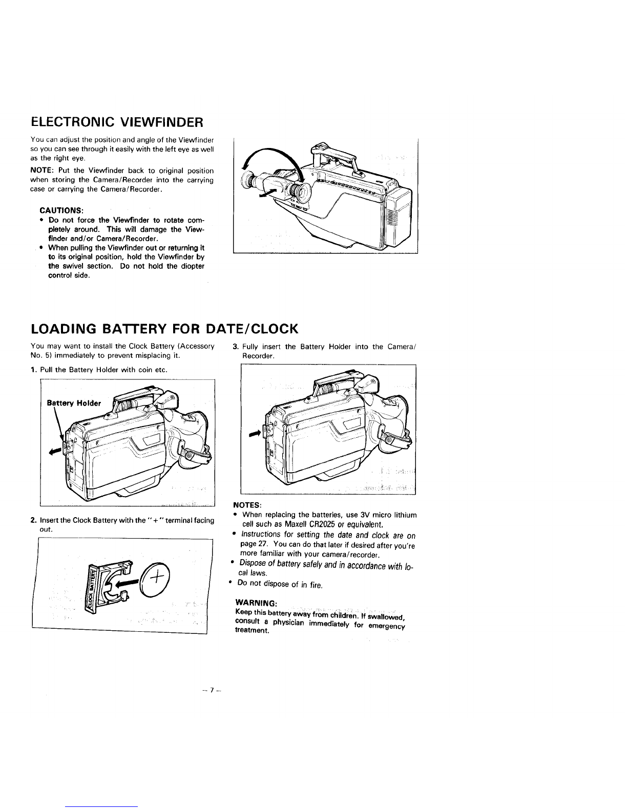
In addition to the careful attention devoted to quality standards in the manufacture of your video product, safety _s_ nJalc,i luctot ill Iht_
design of every instrument But, safety ts your responsibility too
This page lists important information that will help to assure your enloymenl and proper use of a Video CameraJRecorder and accessory
equipment Please read it carefully before operating your video product and keep it in a handy place for future reference
INSTALLATION
1Read and Follow Instructions--All the safety and operat-
ing instructions should be read before the video product
_s operated. Follow all operating and use instructions
2Retain Instructions--The safety and operating mstruc-
tions should be retained for future reference
7Power-Cord Protection--Power-supply cords should be
routed so that they are not likely to be walked on or pinched
by items placed upon or against them, paying particular attention
to cords at plugs, convenience receptacles, and the point where
they exit from the appliance.
8 Ventilation--Slots and opemngs in the cabinet are pro-
vided for ventilation to ensure reliable operation of the video
product and to protect it from overheating. These openings must
not be blocked or covered. The openings should never be blocked
by placing the video product on a bed, sofa, rug, or other similar
surface This video product should never be placed near or over
a radiator or heat register This video product should not be
placed in a built-in installation such as a bookcase or rack unless
proper ventilation is provided or the video product manufacturers
instructions have been followed.
3Heed Warnings--Comply with all warnings on the video
product and in the operating instructions
4Polarized Pluj--This video product is equipped with a
polarized alternating-current line plug (a plug having one
blade wider than the other). This plug will fit into the power outlet
only one way. This is safety feature. If you are unable to insert the
plug fully into the outlet, try reversing the plug. If the plug should
still fail to fit, contact your electrician to replace your obsolete
outlet. To prevent electric shock do not use this polarized plug
with an extension cord, receptacle or
other outlet unless the blades can be I _-----"_
fully inserted without blade exposure If
you need an extension, use a polarized
cord.
5Power Sources--This video product should be operated
only from the type of power source indicated on the
marking label. If you are not sure of the type of power supply to
your home, consult your video dealer or local power company. For
video products intended to operate from battery power, or other
sources, refer to the operating instructions
6Overloading--Do not overload wall outlets and extension
cords as this can result in a risk of fire or electric shock
Overloaded AC outlets and extension cords are dangerous, and
so are frayed power cords, damaged or cracked wire insulation
and broken plugs. They may result in a shock or fire hazard.
Periodically examine the cord and have it replaced by your service
technician if appearance indicates damage or deteriorated insu-
)ation.
9 Attachments--Do not use attachments unless rec
ommended by the video product manufacturer as they may
cause hazards
Caution: Maintain electrical safety Powerline operated equip
merit or accessorjes connected to this unit should bear the UL list-
ing mark or CSA certification mark on the accessory itself and
should not have been modified so as to defeat the safety features
This will help avoid any potential hazard from electric shock or
fire If in doubt, contact qualified service personnel
10 Water and Moisture--Do not use this video product near
water--for example, near a bath tub, wash bowl, kitchen
sink, or laundry tub, in a wet basement, or near a swimming pool,
and the like.
11 Accessories--Do not place this video product on an un-
stable cart, stand, tripod, bracket, or table The video
product may fall, causing serious injury to a child or adult, and
senous damage lo the appliance Use only with a carl, stand,
tripod, bracket, or table recommended by the manufaclurer, or
sold with the video product Any mounting of the product should
follow the manufacturer's instructions, and should use a mounting
accessory recommended by the manufacturer.
11A An appliance and cart
combination should be
moved with care. Quick stops, ex-
cessive force, and uneven surfaces
may cause the appliance and cart
combination to overturn.
3

2Outdoor Antenna Groullding--II dll Ugtbld_:_ JHterlrlLl Ut
cable syslem =s connected to the video product, be sure
tile antenna or cable system is grounded so as to provide some
protection against voltage surges and built-up static charges. Sec-
tion 810 of the National Electrical Code, ANSI/NFPA No. 70-1984,
provides information with respect to proper grounding of the mast
and supporling structure, grounding of the lead-in wire to an
antenna discharge unit, size of grounding conductors, location of
antenna-discharge unit, connection to grounding electrodes, and
requirements for the grounding electrode. See example below.
EXAMPLE OF ANTENNA GROUNDING
LEAO IN
WIRE
FGROUN D CLAMP
I<"
.A_TENNA
j{NECSECTION8_020_
"_!_OUNDING CONDUCTORS
(NECSECTION8_C-21)
_ _ GROUN0CLAMPS
............ --22:::................
EQ_IPt_Et_ ELECTRODE SYSTEM
(NEC ART 250 pART H]
NEC NATIONAL ELECTRICAL CODE
13 Power Lines--An outside antenna system should not be
located in the vicinity of overhead power lines or other
electric light or power circuits, or where it can fall into such power
lines or circuits When installing an outside antenna system,
extreme care should be taken to keep from touching or approach-
mg such power lines or circuits as contact with them might be
fatal Installing an outdoor antenna can be hazardous and should
be left to a professional antenna installer
USE
14 Cleaning--Unplug this video product from the wall outlet
before cleaning. Do not use liquid cleaners or aerosol
cleaners. Use a damp cloth for cleaning
15Object and Liquid Ent_--Never push obiects of any kind
into this video product through openings as they may touch
dangerous voltage points or short-out parts that could result in a
fire or electric shock. Never spill liquid of any kind on the video
product
16 Lightning--l-or added p_utuuilorl tor this videu plo,3uu_
during alightning storm, or when it is left unattended
and unused for long periods of time, unplug it from the wall
outlet and disconnect the antenna or cable-system This will
prevent damage to the video product due to lightning and
power-line surges.
SERVICE
17 Servicing--Do not attempl to service this vrdeo product
yourself as opening or removing covers may expose you to
dangerous voltage or other hazards Refer all servicing to quali-
fied service personnel.
18 Conditions Requiring Service--U nplug this video product
from the wall outlet and refer servicing to qualified service
personnel under Ihe following conditions.
aWhen the power-suppfy cord or plug is damaged
bIf liquid has been spilled, or objects have fallen into the video
product
C. If the video product has been exposed to rain or water.
d. If the video product does not operate normally by following Ihe
operating instructions. Adjust only those controls that are
covered by the operating inslructions. Improper adjustment of
other controls may result in damage and will often require
extensive work by a qualified technician to restore the video
product to its normal operation.
e. Ifthe video product has been dropped or the cabinet has been
damaged.
f. When the video product exhibits a distinct change _n
performance--this indicates a need for service.
19 Replacement Parts--When replacement parts are re-
quired, have the service technician verify that the replace-
ments he uses have the same safety characteristics as the orig-
inal pads. Use of replacements specified by the video product
manufacturer can prevent fire, electric shock or other hazards
20 Safety Check--Upon completion of any service or repairs
to this video product, ask the service techniciarl to perform
safety checks recommended by the manufacturer to determine
thal the video product is in safe operating condition.
4

IMPORTANTSAFETYINSTRUCTIONS
FORAC ADAPTOR/CHARGER
1. Save these instructions -- This page contains
important safety and operating instructions for AC
Adaptor/Charger Model VM-AC66AS.
2. Before using AC Adaptor/Charger, read all instruc-
tions and cautionary markings on (1) AC Adap-
tor/Charger, (2) battery and (3) product using
battery,
3. Also read all instructions on pages 3 and 4.
4. Caution -- To reduce risk of injury, charge only
rechargeable battery, VM-BP64AS, VM-BP66AS,
57-53.983 or 57-53982.
Other types of batteries may burst causing personal
injury and damage.
5. Do not expose charger to rain or snow.
6. Use of an attachment not recommended or sold by
the battery charger manufacturer may result in a
risk of fire, electric shock, or injury to persons.
7. To reduce risk of damage to electric plug and cord,
pull by plug rather than cord when disconnecting
charger.
8. Make sure that cord is properly located so that it
will not be stepped on, tripped over, or otherwise
subjected to damage or stress.
9. Do not operate charger with damaged cord or plug
-- replace them immediately.
10. An extension cord should not be used unless _,b
solutely necessary.
Use of improper extension cord could result in a risk
of fire and electric shock. If extension cord must be
used, make sure:
A. That pins on plug of extension cord are the same
number, size, and shape as those of plug on
charger.
B. That extension cord is properly wired and in
good electrical condition; and
C. That wire size should be met below:
Minimum
AWG size Length of extension cord (feet)
18 Equal to or less than 100
16 Equal to or less than 150
11. Do not operate charger if it has received a sharp
blow, been dropped, or otherwise damaged in any
way; take it to aqualified serviceman.
12. Do not disassemble charger; take it to a qualified
serviceman when service or repair is required. In-
correct reassembly may result in a risk of electric
shock or fire.
13. To reduce risk of electric shock, unplug charger
from outlet before attempting any maintenance or
cleaning.

TABLE OF CONTENTS
Features ......................................................... 2
Accessories .................................................... 2
Important safeguards ...................................... 3
Important safety instructions for
AC Adaptor/Charger .................................... 5
Electronic viewfinder ...................................... 7
Loading battery for date/clock ........................ 7
Power sources ............................................... 8
Battery pack checking .................................... 9
Charging the battery pack ............................. 10
Making asample camera recording ................ 11
Identification and operation of controls .......... 13
Auto focus ................................................... 19
Fade in/Fade out ........................................... 20
Power zoom ................................................. 21
Macro lens ................................................... 21
Instant review ............................................... 22
Program AE (Auto Exposure) ......................... 22
Auto iris ....................................................... 22
Recording TV program .................................. 23
Audio dubbing .............................................. 24
Video dubbing .............................................. 25
Automatic rewind ......................................... 26
Date/clock setting ........................................ 27
Title making ................................................. 29
Index signal recording ................................... 30
Using the built-in camera light ....................... 31
Eyepiece adjustment ..................................... 32
Producing best color program ....................... 32
Viewing the picture played back
on your TV ................................................ 33
Display button .............................................. 35
Linear time counter ....................................... 35
Memory ....................................................... 35
Time remaining ............................................. 36
F-search and R-search ................................... 36
Still .............................................................. 36
Microphone mixing ....................................... 37
Edit search ................................................... 37
Operating hints ............................................. 37
Flying erase head .......................................... 37
Camera/Recorder to VCR dubbing ................. 38
Troubleshooting ............................................ 39
Routine maintenance .................................... 41
Sears service ................................................ 41
How to order repair parts .............................. 41
Specifications ............................................... 41
Using the optional synchro edit cord .............. 42
"Note to CATV system installer: This reminder is provided to call the CATV system installer's attention to
Article 820-40 of the NEC that provides guidelines for proper grounding and, in particular, specifies that
the cable ground shall be connected to the grounding system of the building, as close to the point of cable
entry as practical".
-6

ELECTRONIC VIEWFINDER
You can adjust the position and angle of the Viewfinder
so you can see through it easily with the left eye as well
as the right eye.
NOTE: Put the Viewfinder back to original position
when storing the Camera/Recorder into the carrying
case or carrying the Camera/Recorder.
CAUTIONS:
•Do not force the Viewfinder to rotate com-
pletely around. This will damage the View-
finder and/or Camera/Recorder.
•When pulling the Viewfinder out or returning it
to its original position, hold the Viewfinder by
the swivel section. Do not hold the diopter
control side.
LOADING BATTERY FOR DATE/CLOCK
You may want to install the Clock Battery (Accessory
No. 5) immediately to prevent misplacing it.
1. Pull the Battery Holder with coin etc.
Holder
2. Insert the Clock Battery with the "+" terminal facing
out.
3. Fully insert the Battery Holder into the Camera/
Recorder.
NOTES:
• When replacing the batteries, use 3V micro lithium
call such as Maxall CR2025 or equivalent.
•Instructions for setting the date and clock are on
page 27. You can do that later if desired after you're
more familiar with your camera/recorder.
•Dispose of battery safely and in accordance with lo-
cal laws.
•Do not dispose of in fire.
WARNING:
Keep this battery away from ci_iid;en i ti swaliowed
consult a physician immediately for emergency
treatment.
--7--

POWER SOURCES
•WHEN USING WITH THE BATTERY PACK (Accessory No. 2)
1. To attach, align the mark "11_'" of the fully charged
Battery Pack (Accessory No. 2) with that of the
Video Camera/Recorder, and slide the Battery Pack
downward, as illustrated.
Mark "I_"
Battery Pack
(Accessory No. 2)
2. To remove, _licle thu l_attery Pack OpWdrU white
pushing the "'BA3-rERY'" Eject Lever in the direction
of the arrow.
"BA'rrERY" Eject Lever
•WHEN USING WITH THE AC ADAPTOR/CHARGER (Accessory No. 3)
See the rating label of the AC Adaptor/Charger.
To "DC OUTPUT"
1. Plug the AC Adaptor/Charger power cord into AC
electrical outlet.
2. Connect one end of the DC Cord (Accessory No. 1)
to the "DC IN 9.6 V" jack of the Camera/Recorder.
Connect the other end of the DC Cord to the "'DC
OUTPUT" of the AC Adaptor/Charger.
NOTES:
•The AC Adaptor/Charger cannot charge the Battery
and operate the Camera/Recorder at the same time.
•When using the AC Adaptor/Charger to power the
Camera/Recorder, the battery level indicator may
display "'I_3". This indicator is used for battery
operation and has no meaning when using the AC
Adaptor/Charger to power the Camera/Recorder.
-8-

•WHEN USIN_ WIIH Tri_. _AH UA! It-H¥
(By using optional Car Battery Cord Sears Part P_o. ,,b-Z3868-3)
To cigarette lighter
socket Car Battery Cord (*)
1. Connect the small ;)lug of the Car Battery Cord to the
"DC IN @.6V" jack of the Camera/Recorder.
2. Connect the other end of the Car Battery Cord to the
car's cigarette lighter socket.
(*) Optional--not supplied.
See page 2 for ordering information.
NOTES:
• The Car Battery Cord is _eslgned to be used
only with automobiles having a 12-volt negative
ground system.
•To prevent fire or shock hazard or damage to
your camera/recorder, please use only with
Sears car battery cord (Part No. 46-23858-3).
BATTERY PACK CHECKING
When the" gPl "' indication in the Electronic Viewfinder
appears and flashes while the Video Camera/Recorder
is operated with a Battery pack (Accessory No. 2), it in-
dicates that the battery charge is insufficient. Then,
charge it or replace it with a charged battery pack.
NOTE: Whenever the linear time counter or tape re-
maining display is present in the viewfinder, the battery
level indicator "'C_] "" is displayed in the viewfinder in-
dicating the condition of Camera/Recorder battery
power. When the Battery is fully charged, "_Z]" is
displayed.
After several minutes, the symbol will change to
"" _"'. When the Battery is very near empty, the sym-
bol will change to "_ "and start blinking. You should
find an alternative power source or recharge the battery
before continuing to use your Camera/Recorder.
¸¸!5¸!¸¸¸
0 O0 O0 < i 0 2500
aF"
0 50 O0
-- 9-

CHARGING THE BATTERY PACK
1. Plug the AC Adaptor/Charger (Accessory No. 3)
power cord into AC electrical outlet.
2. Attach the Battery to the AC Adaptor/Charger.
Align the reference arrow on the Battery with that of
AC Adaptor/Charger and push the Battery.flush with
the AC Adaptor/Charger and slide it in the direction
of arrow.
NOTE: You must remove the DC cord from the AC
Adaptor/Charger to charge the battery. If the DC
cord is connected, "CHARGE" Light will not light.
3. The "CHARGE" Light will be lit while the Battery is
accepting a charge, and will go out when the Battery
is fully charged.
"CHARGE" Light
Light
NOTES:
1. The time required for charging the Battery is
approx, two hours.
2. When fully charged, the Battery should supply
approx. 45 - 60 minutes of operating time (de-
pending on how much you use zoom and pause).
3. An optional long play battery (Sears Stock No.
57-53983) may also be charged by the AC Adap-
tor/Charger. The time for battery charging is ap-
prox. three hours.
4. Charge the Battery after use and store it at nor-
mal room temperature.
5. Recharge your Battery at least once every six
months. The Battery is a Lead-acid Battery.
This Battery tends to discharge if not used for an
extended period of time. If the Battery is stored
for a extended length of time without being
recharged, you may not be able to recharge it.
6. ABattery charged after being stored for a long
period may not supply power for the specified
time. Additional rechargings will help restore the
Battery's operation time.
7. The Battery should be charged at a temperature
of 32°F -- 95°F (0°C -- 35°C) to prevent
damage.
8. Do not operate the Battery at temperatures be-
low 14°F (--10°C) or above 95°F (35°C). The
Battery may be damaged if operated at temper-
atures above 122°F (50°C). Operation time will
decrease at extremely low temperatures.
9. After repeated chargings and use, the operation
time will gradually decrease. When operation
time becomes too short to be useful, it is time to
replace the Battery.
10. If "CHARGE" and "POWER" Lights on the AC
Adaptor/Charger start flashing, remove the bat-
tery and then reattach it. If after several at-
tempts both Lights continue to flash, this means
your battery cannot take a charge and must be
replaced with a new one.
The "CHARGE" Light will not light if a hot bat-
tery is attached to the AC Adaptor/Charger. At-
taching an extremely hot Battery to the AC
Adaptor/Charger is not recommended; it should
be allowed to cool down before being attached.
11. Do not short the Battery's terminal.
12. Do not attempt to disassemble or modify the Bat-
tery. There are no user serviceable parts inside.
13. Throwing the Battery into a fire or exposing the
Battery to excessive heat -- over 149°F (65°C)
could be hazardous.
14. Be sure to set the "POWER" Switch to the
"OFF" position before removing the Battery.
ATFENTION:
The product that you have purchased contains a rechargeable battery. The battery
is recyclable. At the end of its useful life, under various state and local laws, it may
be illegal to dispose of this battery into the municipal waste stream. Check with your
local solid waste officials for details in your area for recycling options or proper
disposal. Pb
10

MAKING A SAMPLE CAMERA
1. Connect the POWER SOURCE. (See pages 8 and
9.)
2. Press "EJECT" Button and insert the cassette so
the transparent window is toward you and the
arrow toward the Cassette Holder. Slide the
Cassette into Cassette Holder as far as it will go..
NOTE: Push in the center of the Cassette all the
way until it is latched by the Cassette Holder.
3. Press the Cassette Holder. The Holder will latch in
the operating position.
"EJECT" Button
Cassette Holder
4. Press and hold the small button on "POWER"
Switch while sliding it to the "CAM" position.
The "POWER" indicator will light and the Video
Camera/Recorder will enter record/pause mode
automatically.
NOTE: If the erase prevention tab on the cassette
is removed, "TAPE" in the Viewfinder will flash for
several seconds and the Camera/Recorder will not
enter record/pause mode and recording is not
possible.
"POWER" Switch
RECORDING
5. Set "FOCUS AUTO/MAN" Switch tu "AUTO".
NOTE: See page 32 for "EYEPIECE ADJUST-
MENT".
"REC/STILL" Button
7.
"FOCUS AUTO/MAN" Swltch
Now, press Record Start/Stop or "REC/STILL"
Button to start shooting the picture. "REC" indi-
cation appears in the viewfinder and you are now
recording the picture you see through the Elec-
tronic Viewfinder.
Press Record Start/Stop or "'REC/STILL" Button
to stop recording. Press the Button again to re-
sume recording. The "'REC" indication in the Elec-
tronic Viewfinder goes off in the record/pause
(stand-by) mode.
NOTE: The "TAPE END" indication starts flash-
ing in the Viewfinder when there is less than three
minutes recording time left on the cassette.
Record Start/Stop Button
-11--

I_. Attel rucurd_flg, plu,_s dlJd hold ttlu sIHail buttoll on
"POWER" Switch while you slide it to "'VOR",
and the Camera/Recorder will be now in the stop
mode.
12. Press arid hold the small button oil "POWER"
Switch while you place it in "OFF" position to turn
off the Camera/Recorder, and then press "EJECT"
Button to remove cassette.
"POWER" Switch
9. Press'REW'" Button. The tape will be rewound to
the beginning.
10. Press "PLAY" Button. The picture you just
recorded will be seen through the Viewfinder and
sound can be heard by earphone (Not supplied).
NOTE: If you connect the Video Camera/Recorder
to your TV, you can see the picture played back on
your TV. Refer to "VIEWING THE PICTURE
PLAYED BACK ON YOUR TV" on pages 33 and
34.
11. After playing, press "STOP" Button.
"POWER" Switch
13. Always remove the power source from the Video
Camera/Recorder after use.
,REW" Button
"PLAY" Button
"sTop"
// IIIIW
To prevent an accidental erasure of recorded
material:
If you have a cassette tape that has already been
partially recorded on and you want to record on the
remaining blank section, see "EDIT SEARCH" on
page 37.
-12

IDENTIFICATION AND OPERATION OF CONTROLS
Record Indicator
This indicator lights during the record mode
and goes off during the stand-by (record/
pause) mode.
Camera Light
If the camera light is raised when _.he
"POWER" Switch is set to "CAM", it lights
automatically. Return the light to its original
position after using it; it turns off automatically.
NOTE: If the "POWER" Switch is set to
"VCR" or "OFF", the camera light does not
turn on even when it is raised.
"REVIEW" Button
Used to review the lastfew secondsof the re-
corded segment in the record/pause
(See page 22.)
Zoom Ring (Manual Zooming)
The picture size can be magnified !2 times with
the use of the zoom feature. Just rotate
Zoom Ring for a close up (T) or wide angle (W)
picture. Macro close-up, as close as 1cm from
object, is possible.
"MACRO" Button
Used to shoot objects as close as 1cm from the
lens tip.
(See "MACRO LENS" on page 21.)
Focus Ring
Do not attempt to manually turn the Focus
Ring when the Camera/Recorder is in the auto
focus mode.
Lens (with Lens Capl
F2.2 (6.7-80.4 ram) 12:1 power zoom lens
features auto focus and auto iris functions.
Auto Focus Window
To automaticatly focus the camera lens,
window transmits and receives infrared light
which is reflected off the object. Make sure
you don't obstruct this window when
recording.
Microphone
Sensitiveto soundscomingfrom the di,
in which the camera is pointed.
"TITLE" Button
Press this Button to create and record persona-
lized titles on your videos with the Camera/
Recorder's built-in titler.
_See "TITLE MAKING" on page 29.)
"RESET/T-160/T-180" Button
When the linear time counter is displayed in the
viewfinder, pressing this Button resets the
counter to "0:00:00".
When the time-remaining read-out is displayed,
pressing this Button changes the display for ex-
tended length T-160 or T-180 tape. "'T-160" or
"T-180" will appear in the viewfinder.
-13-

L_io_J L_I _orl[roJ
TO use the Electronic V_ewill_Uuf vv,[hout _y_
glasses on, turn this control ring for your opti-
mum focus adjustment.
Electronic Viewfinder (EVF)
Displays what the Camera/Recorder lens sees.
The electronic viewfinder also functions as a
convenient black-and-white monitor during
playback of recorded material.
"PUSH/AUTO" Focus Button
Auto focusing can be also performed during
manual focus mode by pushing this Button.
"DISPLAY" Button
Pressing this Button once causes a5 digit linear
counter and battery indicator to appear in
the Camera/Recorder's viewfinder.
Pressing the Button again will cause battery in-
dicator and the amount of time remaining on
the cassette in the Camera/Recorder. Press a
third time to delete all displays.
"DATE/TIME" Button
Press this Button to display the date and clock
in the vievvfinder.
Whenever the date and clock appear in the
viewfinder, they will be recorded on the tape.
"MEMORY" Button
If this Button is pressed while the linear time
counter or time remaining read-out is displayed
in the viewfinder, "'M'" appears in the display
and it memorizes the tape position of
"0:00:00".
(See page 35.)
"FADE" Button
=During recording you can add aprofessional
touch to your recordings by fading in and out
of scenes,
NOTE: When you use "FADE" Button to fade
in and out, the sound will also fade in and out
with the picture. (See page 20.)
"FOCUS AUTO/MAN" Switch
Set this :Switch to the "AUTO" position for
automatic focusing, and to the "MAN"
position for focusing with the Focus Ring.
14-

"REWIND" Button
Press this Button during Stop (Jr Fast lorward
mode, and fast-rewinding starts. "REWIND"
appears in the viewfinder whenever the linear
time counter or time remaining is present.
Press the Button during playback of tape, and
the tape is played back in the rewind direction
approximately 3 times faster than the normal
speed to confirm the recorded contents.
Press "PLAY" Button to return to normal play-
back mode or press "STOP" Button to stop
tape movement.
NOTE: You can also visually scan backward
when the Camera/Recorder is in record/
(stand-by) mode by pressing and holding this
Button.
"EJECT" Button
Operateswith "POWER" either on or off, if a
power source is connected to the Camera
Recorder.
"PLAY" Button
Used for playback of tape _colded in the SP
mode.
NOTE: When the Camera/Recorder is in
record/pause (stand-by) mode, pressing and
holding this Button will play the tape at normal
speed.
"POWER" Light
"POWER" Switch
This Switch changes the Camera
the record mode or to the playback mode.
Press and hold the small button on this Switch
while sliding it to "CAM", "OFF" or "'VCR".
"EAR"phone Jack
Sound being recorded by the microphone ol
played back may be monitored by attaching
earphone (Not supplied) to this jack.
"MIC" Jack
Connect an external microphone (Not supplied)
here to record sound from the external
microphone.
NOTE: Connecting an external microphone
automatically switches off the built-in
microphone.
"MIC WIND/NORM" Switch
This Switch is used to reduce
due to wind.
Set the Switch to the "NORM" position for
normal use.
,i
'INORMCAMIOIFFVCR EJECT--,REW PLAY
MIC POWER TITLE_ -- PAGE
newwl=umle=hi=
-15

"F.FWD"-Buttol_
Press this Button during Stop or Rewind fllode,
and fast-forwarding starts. "FAST FWD" ap-
pears in the viewfinder whenever the linear time
counter or time remaining is present.
Press the Button during playback of tape, and
the tape is played back in the forward direction
approximately 3 times faster than the normal
speed to confirm the recorded content.
Press "PLAY" Button to return to normal play-
back mode or press "STOP" Button to stop
tape movement.
NOTE: You can also visually scan forward
when the Camera/Recorder is in record/pause
(stand-by) mode by pressing and holding this
Button.
:.F_/D STOP anSTILL AUDIO VIDEO TRACKING
-I- SHIFT iREC I--DUB--I
"STOP" Button
The "STOP" Button is used to stop playback,
rewind, and fast forward operations. The
"STOP" Button has no effect during record
operation.
//"REC/STILL'" Button
When this Button is pressed during recording,
the tape stops and the Camera/Recorder enters
the record/pause (stand-by) mode. When this
Button is pressed again, the tape runs to
resume recording.
This Button may be also used to
display a still picture during playback mode.
"AUDIO DUB" Button
This Button is used to record new audio in
of existing audio without erasing the
video. See page 24.
"VIDEO DUB" Button
Button is used to record new video in
place of existing video without erasing the
audio. See page 25.
•These Buttons are used for title making
buttons when the "TITLE" Button is
pressed. (See "TITLE MAKING" on page
29.)
• These Buttons may be also used to set the
date and clock during pause (stand-by)
mode. (See "DATE/CLOCK SE'R'ING" on
page 27.)
"TRACKING" Control
Used when playing a tape recorded on another
VCR. Adjust for best picture. Ejecting the cas-
sette returns the tracking to the normal
position.
CAUTION:
Do not hold the unit by the Viewflnder when
carrying as this could cause a malfunction.
16

"BA'I-rERY" Eject Lever
Releases the Battery attached to the Video
Camera/Recorder.
Clock Battery Compartment
Pull the Battery Holder and install the Clock
Battery (Accessory No. 5).
Cassette Holder
Press "EJECT" Button to open the Cassette
Holder. Be aware of the Cassette direction_
when inserting.
NOTE: Power source must be connected to
open the Cassette Holder.
"'DC IN 9.6V'" Jack
When using the AC Adaptor/Charger (Acces-
sory No.3) or the Car Battery Cord (optional),
connect this jack and the "'DC OUTPUT" of
the AC Adaptor/Charger or the car's cigarette
lighter socket.
"MIC MIX (ON/OFF)" Switch
This Switch lets you add additional comments
(or music) to a tape while you are copying a
tape from your camera/recorder onto another
VCR.
"AV OUT" Jack
Connect the Audio/Video Output Cable (Ac-
cessory No. 4) to this jack and to the audic
video inputs of your TV/monitor receiver. You
may also connect the RF Converter Unit (op-
tional) to this jack and your TV receiver.
"'AV IN" Jack
Use this connector jack when you want to con-
nect signals from another device into your
Camera/Recorder for recording.
17

Power Zoom Switch
.... _-_'_This Switch performs zooming electrically.
"W": Picture becomes wider gradually.
"T": Picture becomes telescopic gradually.
Record Start/Stop Button
This Button is used to control the Camera/
Recorder. When this Button is pressed with
the Camera/Recorder set to the recording
mode, the tape runs to start recording. "REC"
,ppears in the viewfinder.
When this Button is pressed again, "'PAUSE"
appears instead of "'REC" and the tape stops
and the Camera/Recorder enters the record/
pause (stand-by) mode.
Lens Cap Tab
Place the lens cap on this tab when you are
ready to record a scene. The tab also prevents
the lens cap from swinging around on its cord.
Hand Strap
Adjust to best fit to your hand.
Graphics in the Electronic Viewfinder
TAPE I
0:00:00 REC
Displays the shutter speed according to the lighting condition.
r---Indicates the battery condition;
I" When the battery is fully charged, "_" is displayed. When the bat-
_ . tery isvery near empty, "IF" starts blinking. You should find an alter-
£J native power source or recharge the battery.
When the Record Start/Stop Button is pressed, if acassette without its
safety tab is inserted, "TAPE" blinks for several seconds. When the
Record Start/Stop Button is pressed, if no cassette is inserted, "NO
TAPE" blinks for several seconds.
]0/]2:02AM]/934_ Indicates the date/clock during the record or record/pause (stand-by)
mode. You can record the clock and/or date with object when
recording.
Indicates the operating modes;
•"'REC'" appears during the record mode.
•"REWIND" appears during the rewind mode.
•"FAST FWD'" appears during the fast forward mode.
•"PAUSE" appears during the record/pause (stand-by) mode.
•Shows linear time counter and time remaining.
18

AUTO FOCUS
The auto focus system utilizes
Infrared light and will focus on
the nearest object that reflects
this light.
Auto Focus Window
Auto focusing can also be_ --FOCUS
, PUSFI/AUTO MAN • • AUTO
performed during manual_
focus mode by pushing this _
Button.
When the "FOCUS AUTO/MAN" Switch is set to "AUTO" position, ordinary objects are automatically in optimum
focus.
•OBJECTS HARD TO AUTO FOCUS
The distance between the Auto Focus Window and the object is measured, and the Focus Ring is automatically turned
for focusing. However, with the scenes such as shown below, the auto focusing may not operate properly, and
manual focus must be performed. See next page.
1. Object is not in the
center. 2. Object in far and near
positions at the same
time.
3. Object with continuous
variation from far to
near positions.
4. Object behind glass.
5. Black object or water
which does not reflect
infrared light.
6. Object always moving
such as a crowd.
/'l., 1
_, <_ >_. ".o .. ,.
t ', '5 "° J
7, Object in the snow or
fog. 8. Objects more than 50
feet away.
19
Table of contents
Other Sears Camcorder manuals
Popular Camcorder manuals by other brands

Panasonic
Panasonic Palmcoder PalmSight PV-L550 operating instructions

Hitachi
Hitachi DZ-MV580E Specifications

Sony
Sony HANDYCAM DCR-TRV130ERMT-814 Service manual

Sony
Sony PMW-150 operating instructions

Pinnacle Systems
Pinnacle Systems Dazzle 150 quick start guide

JVC
JVC GY-HD200UB - Camcorder - 1080i owner's manual