TRIGGER
Fig. 1
..-CAP
SCREW
A
lL
FORWARD
REVERSE -
VARIABLE SPEED
CONTROL SELECTOR
AUXILIARY HANDLE
'0' HANDLE
LOCK-ON BUTTON
The operation of any Drill can result in foreign objects being thrown into your
eyes, which can result in severe eye damage. Before commencing power tool
operation, always wear safety goggles or safety glasses with Side shields and
a full face shield when needed. We recommend Wide Vision Safety Mask for
use over spectacles or standard safety glasses with side shields, available at
Sears Catalog Order or Retail Stores.
ACAUTION:
Page 5
OPERATION
OPERATION (Cont.)
KNOW YOUR DRILL
Before attempting to use your drill, familiarize
yourself with all operating features and safety re-
quirements.
WARNING: DO NOT ALLOW FAMILIARITY
WITH YOUR DRILL TO
MAKE
YOU CARELESS.
REMEMBER
THAT A CARELESS FRACTION OF A
SECOND IS SUFFICIENT TO INFLICT
SEVEREIN-
JURY.
WARNING: ALWAYS WEAR SAFETY GLASSES
OR EYESHIELDS WHEN OPERATING YOUR
DRILL. FAILURE TO DO SO COULD RESULT IN
DUST, SHAVINGS, OR LOOSE PARTICLES BEING
THROWN INTO YOUR EYES, RESULTING IN
POSSIBLE SERIOUS INJURY.
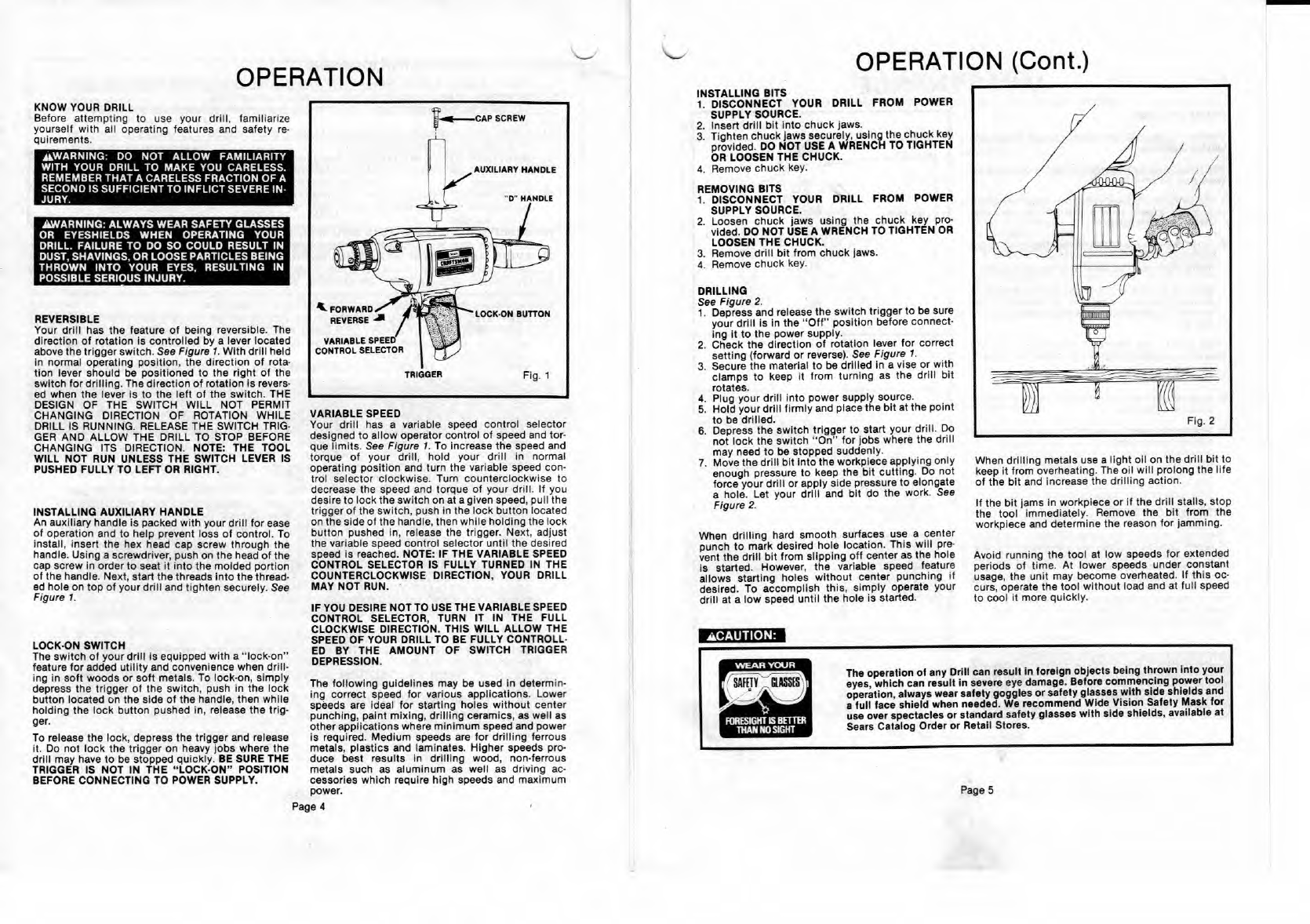
REVERSIBLE
Your drill has the feature of being reversible. The
direction of rotation is controlled by a lever located
above the trigger switch.
See Figure 1.
With drill held
in normal operating position, the direction of rota-
lion lever should be positioned to the right of the
switch for drilling. The direction of rotation is revers-
ed when the lever is to the left of the switch. THE
DESIGN OF THE SWITCH WILL NOT PERMIT
CHANGING DIRECTION OF ROTATION WHILE
DRILL IS RUNNING. RELEASE THE SWITCH TRIG-
GER AND ALLOW THE DRILL TO STOP BEFORE
CHANGING ITS DIRECTION. NOTE: THE TOOL
WILL NOT RUN UNLESS THE SWITCH LEVER IS
PUSHED FULLY TO LEFT OR RIGHT.
INSTALLING AUXILIARY HANDLE
An auxiliary handle is packed with your drill for ease
of operation and to help prevent loss of control. To
install, insert the hex head cap screw through the
handle. Using a screwdriver, push on the head of the
cap screw in order to seat it Into the molded portion
of the handle. Next, start the threads into the thread-
ed hole on top of your drill and tighten securely. See
Figure 1.
LOCK-ON SWITCH
The switch of your drill is equipped with a lock-on'
feature for added utility and convenience when drill-
ing in soft woods or soft metals. To lock-on, simply
depress the trigger of the switch, push in the lock
button located on the side of the handle, then while
holding the lock button pushed in, release the trig-
ger.
To release the lock, depress the trigger and release
it. Do not lock the trigger on heavy jobs where the
drill may have to be stopped quickly.
BE
SURE THE
TRIGGER IS NOT IN THE "LOCK-ON" POSITION
BEFORE CONNECTING TO POWER SUPPLY.
VARIABLE SPEED
Your drill has a variable speed control selector
designed to allow operator control of speed and tor-
que limits.
See Figure 1.
To increase the speed and
torque of your drill, hold your drill in normal
operating position and turn the variable speed con-
trol selector clockwise. Turn counterclockwise to
decrease the speed and torque of your drill. If you
desire to lock the switch on at a given speed, pull the
trigger of the switch, push in the lock button located
on the side of the handle, then while holding the lock
button pushed in, release the trigger. Next, adjust
the variable speed control selector until the desired
speed is reached. NOTE: IF THE VARIABLE SPEED
CONTROL SELECTOR IS FULLY TURNED IN THE
COUNTERCLOCKWISE DIRECTION, YOUR DRILL
MAY NOT RUN.
IF YOU DESIRE NOTTO USETHE VARIABLE SPEED
CONTROL SELECTOR, TURN IT IN THE FULL
CLOCKWISE DIRECTION. THIS WILL ALLOW THE
SPEED
OF YOUR DRILL TO BE FULLY CONTROLL-
ED BY THE AMOUNT OF SWITCH TRIGGER
DEPRESSION.
INSTALLING BITS
1.
DISCONNECT YOUR DRILL FROM POWER
SUPPLY SOURCE.
2.
Insert drill bit into chuck jaws.
3.
Tighten chuck jaws securely, using the chuck key
provided.
DO NOT USE A WRENCH
TO TIGHTEN
OR LOOSEN THE CHUCK.
4.
Remove chuck key.
REMOVING BITS
1.
DISCONNECT YOUR DRILL FROM POWER
SUPPLY SOURCE.
2.
Loosen chuck jaws using the chuck key pro-
vided.
DO NOT USE A WRENCH
TO TIGHTEN OR
LOOSEN THE CHUCK.
3.
Remove drill bit from chock jaws.
4.
Remove chuck key.
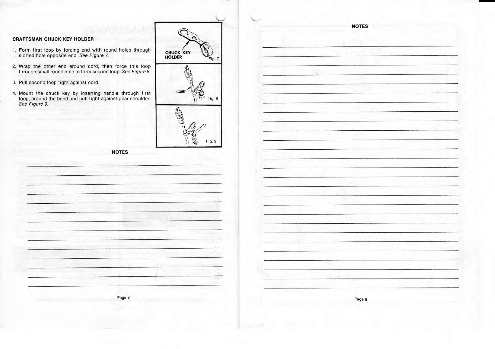
DRILLING
See Figure
2.
1.
Depress and release the switch trigger to be sure
your drill is in the "Off' position before connect-
ing it to the power supply.
2.
Check the direction of rotation lever for correct
setting (forward or reverse).
See Figure 1.
3.
Secure the material to be drilled in a vise or with
clamps to keep it from turning as the drill bit
rotates.
4.
Plug your drill into power supply source.
5.
Hold your drill firmly and place the bit at the point
to be drilled.
6.
Depress the switch trigger to start your drill. Do
not lock the switch "On" for jobs where the drill
may need to be stopped suddenly.
7.
Move the drill bit into the workplace applying only
enough pressure to keep the bit cutting. Do not
force your drill or apply side pressure to elongate
a hole. Let your drill and bit do the work.
See
Figure 2.
When drilling hard smooth surfaces use a center
punch to mark desired hole location. This will pre-
vent the drill bit from slipping off center as the hole
is started. However, the variable speed feature
allows starting holes without center punching if
desired. To accomplish this, simply operate your
drill at a low speed until the hole is started.
When
When drilling metals use a light oil on the drill bit to
keep it from overheating. The oil will prolong the life
of the bit and increase the drilling action.
If the bit
tams
in workpiece or if the drill stalls, stop
the tool immediately. Remove the bit from the
workplace and determine the reason for lamming.
Avoid running the tool at low speeds for extended
periods of time. At lower speeds under constant
usage, the unit may become overheated. If this oc-
curs, operate the tool without load and at full speed
to cool it more quickly.
The following guidelines may be used in determin-
ing correct speed for various applications. Lower
speeds are ideal for starting holes without center
punching, paint mixing, drilling ceramics, as well as
other applications where minimum speed and power
is required. Medium speeds are for drilling ferrous
metals, plastics and laminates. Higher speeds pro-
duce best results in drilling wood, non-ferrous
metals such as aluminum as well as driving ac-
cessories which require high speeds and maximum
power.
Page