Seaside DCT 5000 User manual
Digital Cable Box
USER MANUAL
DCT 5000
Wiring Instructions
Additional Information
SEASIDE TV

CAUTION
RISK OF ELECTRIC SHOCK
REFER SERVICING TO QUALIFIED SERVICE PERSONNEL.
TO REDUCETHE RISK OF ELECTRIC SHOCK,
DO NOT REMOVE COVER (OR BACK).
NO USER-SERVICEABLE PARTS INSIDE.
CAUTION:
Graphical symbols and supplemental warning marking locations on bottom of terminal.
WARNING
TO PREVENT FIRE OR SHOCK HAZARD, DO NOT EXPOSE THIS APPLIANCE TO
RAIN OR MOISTURE.
CAUTION
TO PREVENT ELECTRICAL SHOCK, DO NOT USE THIS (POLARIZED) PLUG
WITH AN EXTENSION CORD, RECEPTACLE, OR OTHER OUTLET UNLESS
THE BLADES CAN BE FULLY INSERTED TO PREVENT BLADE EXPOSURE.
The lightning ash with arrowhead symbol, within an equilateral triangle, is
intended to alert the user to the presence of uninsulated “dangerous voltage”
within the product’s enclosure that may be of sufcient magnitude to constitute
a risk of electric shock to persons.
The exclamation point, within an equilateral triangle, is intended to alert the
user to the presence of important operating and maintenance (servicing)
instructions in the literature accompanying the appliance.
This installation should be made by a qualied service person and should conform to all
local codes.
REPAIRS
If you nd the unit in need of repair, contact your cable system operator for repair or
replacement.
NOTE TO CATV SYSTEM INSTALLER
This reminder is provided to call the CATV system installer’s attention to Article 820-40 of
the NEC that provides guidelines for proper grounding and, in particular, species that the
cable ground shall be connected to the grounding system of the building, as close as
possible to the point of cable entry as practical.
EXAMPLE OF ANTENNA GROUNDING
A n t en n a l ea d
in w ire
G ro un d
cla m p
A n t en n a
d is ch ar ge u n it
(N E C Se ct io n 8 10 -2 0 )
G ro un d in g co nd u c to r s
(N E C S ec tio n 8 1 0-21)
G ro un d in g
c la m p s
P ow e r s er v ic e g ro u n d in g
elect ro d e s ys tem
(N E C A r t ic le 2 50 , P a r t H )
E le c tr ic s er vice
eq uip m e nt
N EC =N AT IO N A L EL EC T RIC A L CO D E

IMPORTANT SAFEGUARDS
1Read instructions
All the safety and operating instructions should
be read before the appliance is operated.
2Retain instructions
The safety and operating instructions should be
retained for future reference.
3Heed warnings
All warnings on the appliance and in the
operating instructions should be adhered to.
4Follow instructions
All operating and use instructions should be
followed.
5Cleaning
Unplug this product from the wall outlet before
cleaning. Do not use liquid cleaners or aerosol
cleaners. Use a damp cloth for cleaning.
6Attachments
Do not use attachments not recommended
as they may cause hazard.
7Water and moisture
Do not use this equipment near water; for
example, near a bath tub, wash bowl, kitchen
sink, or laundry tub, in a wet basement, or near
a swimming pool, and the like.
8Accessories
Do not place this product on an unstable cart,
stand, tripod, bracket, or table. The product may
fall causing serious injury and serious damage to
the appliance. Use only with a cart, stand, tripod,
bracket, or table recommended by the
manufacturer, or sold with the equipment. Any
mounting of the appliance should follow the
manufacturer’s instructions, and should use a
mounting accessory recommended by the
manufacturer.
9Ventilation
Slots and openings in the cabinet are provided for
ventilation and to ensure reliable operation of the
equipment and to protect it from overheating. The
openings should never be blocked by placing the
product on a bed, sofa, rug, or similar surface.
Equipment should never be placed near or over a
radiator or heat register, or in a built-in installation
such as a bookcase or rack unless proper
ventilation is provided.
1 0 Power sources
This product should be operated only from the
type of power sources indicated on the marking
label. If you are not sure of the type of power
supplied to your home, consult your local power
company. For equipment intended to operate from
battery power, or other sources, refer to the
operating instructions.
1 1 Ground or polarization
This equipment may be equipped with a polarized
alternating-current line plug (a plug having one
blade wider than the other). This plug will t into
the power outlet only one way. This is a safety
feature. If you are unable to insert the plug fully
into the outlet, try reversing the plug. If the plug
should still fail to t, contact your electrician to
replace your obsolete outlet. Do not defeat the
safety purpose of the polarized plug.
1 2 Alternate warnings
This equipment may be equipped with a 3-wire
grounding-type plug, a plug having a third
(grounding) pin. This pin will only t into a
grounding-type power outlet. This is a safety
feature. If you are unable to insert the plug into
the outlet, contact your electrician to replace your
obsolete outlet. Do not defeat the safety purpose
of the grounding-type plug.
1 3 Power cord protection
Power supply cords should be routed so that they
are not likely to be walked on or pinched by items
placed upon or against them, paying particular
attention to cords at plugs, convenience
receptacles, and the point where they exit from
the appliance.
1 4 Outdoor Antenna Grounding
If an outside antenna or cable system is connected
to the equipment, be sure the antenna or cable
system is grounded as to provide some protection
against voltage surges and built-up static charges.

1 5 Lightning
For added protection for this equipment during
a lightning storm, or when it is left unattended
and unused for long periods of time, unplug it
from the wall outlet and disconnect the antenna
or cable system. This will prevent damage to
the video product due to lightning and power
line surges.
1 6 Power lines
An outside antenna system should not be
located in the vicinity of overhead power lines
or where it can fall into such power lines or
circuits. When installing an outside antenna
system, extreme care should be taken to keep
from touching such power lines or circuits as
contact with them may be fatal.
1 7 Overloading
Do not overload wall outlets and extension
cords as this can result in a risk of re or
electrical shock.
1 8 Object and liquid entry
Never push objects of any kind into this
equipment through openings as they may touch
dangerous voltage points or short-out parts that
could result in a re or electrical shock. Never
spill liquid of any kind on the product.
1 9 Servicing
Do not attempt to service this equipment
yourself as opening or removing covers may
expose you to dangerous voltage or other
hazards, refer all servicing to qualied
service personnel.
2 0 Damage requiring service
Unplug this equipment from the wall outlet and
refer servicing to qualied service personnel under
the following conditions:
aWhen the power supply cord or plug is
damaged.
bIf the equipment has been exposed to rain
or water.
cIf liquid has been spilled, or objects have fallen
into the equipment.
dIf the equipment does not operate normally by
following the operating instructions. Adjust
only those controls that are covered by the
operating instructions as an improper
adjustment of other controls may result in
damage and will often require extensive work
by a qualied technician to restore the
equipment to its normal operation.
eIf the equipment has been dropped or cabinet
has been damaged.
fWhen the equipment exhibits a distinct change
in performance, indicating a need for service.
2 1 Replacement parts
When replacement parts are required, be sure the
service technician has used replacement parts
specied by the manufacturer or have the same
characteristics as the original part. Unauthorized
substitutions may result in re, electric shock, or
other hazards.
2 2 Safety check
Upon completion of any service or repairs to this
video product, ask the service technician to
perform safety checks to determine that the
product is in proper operational condition.
2 3 Telephone equipment
Observe the following precautions when installing
telephone modem equipment:
aNever install telephone wiring during a
lightning storm.
bNever install telephone jacks in a wet
location unless the jack is specically designed
for wet locations.
cNever touch uninsulated telephone wires or
terminals unless the telephone lines have been
disconnected at the network interface.
dUse caution when installing or modifying
telephone lines.
2 4 Battery usage
Notwithstanding any information provided by GI in
this manual regarding the use of batteries, the end
user assumes all responsibility and liability to use
and dispose of batteries in accordance with all
applicable laws, rules and regulations. GI will not
be liable to anyone for the end user’s failure to use
and/or dispose of batteries in the proper manner
and in accordance with such laws, rules and
regulations, or for any defect contained in
batteries which may cause injury damage to
persons or property.

CONTENTS
Introduction..................................................2
Front Panel..........................................................................3
Rear Panel ...........................................................................4
Recording Your Connections ...................... 7
Remote Control ............................................8
Installing Batteries .......................................................... 12
Basic Operation ........................................... 13
Turning Power On and Off.......................................... 13
Changing Channels......................................................... 13
Adjusting the Volume.................................................... 13
Audio/Video Connections.......................... 14
RF Bypass Switch.............................................................15
Data Features ..............................................18
Data Device Connection ..............................19
Troubleshooting......................................... 20

2
I NT R O D UC TIO N
This handbook will introduce you to the basic features of the DCT 5000 and
provide several options for integrating it into your current entertainment
system.

3
INTRODUCTION
Front Panel
The DCT 5000 front panel has 12 keys and an LED display. Use the keys to
perform basic functions such as access the electronic program guide, navigate
menus, and purchase pay-per-view events.
The LED can display the currently selected channel or time of day, depending
on your default setting in the electronic program guide. For more
information on the front panel, see the Remote Control section.
,1752 $%
0(1 8
*8, ' (
32:( 5 6(/(&7
&
+
$
1
1
(
/
&
8
5
6
2
5
60$57&$5'
3
087(
06* 6
21 5(0 27 (
$%
4
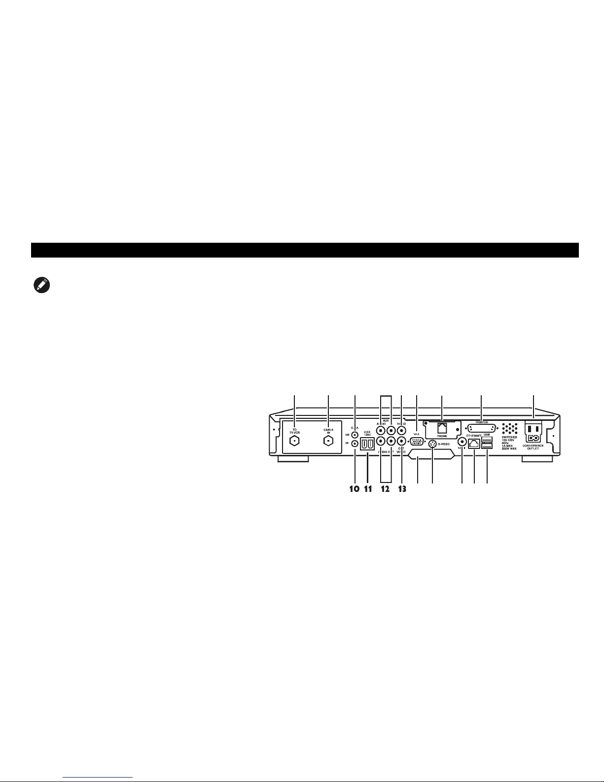
INTRODUCTION
NOTE
The rear panel of your DCT 5000 may vary from this
drawing because of different configurations that are
available. Please contact your service provider to
determine which connections are supported on your
system.
Rear Panel
The DCT 5000 was designed to connect to more than a standard TV. The
rear panel consists of two types of interfaces — audio/video and data. The
table following this drawing describes each connection and its potential use.
9*$
63',)
10 11 12 13 14
15
16
17
18
123456
7
89

5
INTRODUCTION
Key Description
1TO TV/VCR This coaxial output connector, when operating on channel 3 or 4, is used to connect the DCT 5000 to a TV or
VCR.
2CABLE IN The CABLE IN connector provides the incoming signal from your service provider.
3DATA HS For future use.
4AUX AUDIO IN R
AUX AUDIO IN L
These connectors are used for connecting the set-top between a CD player and a stereo tuner (or other audio
peripheral). Audio from the auxiliary device will pass through the DCT 5000 when it is turned off.
5IN VIDEO This connector can accept a baseband video input from a VCR, camcorder, or other video device.
6VGA This is an SVGA interface connector for a monitor or other SVGA video display device.
7PHONE The phone connector enables interface from an in-home phone line to the DCT 5000 modem.
8PRINTER This parallel port is used to interface to a printer or other parallel port device.
9CONVENIENCE
OUTLET
This is the AC outlet to connect the power plug from the TV to the DCT 5000.
10 DATA IR This connector enables the DCT 5000 to control a VCR while recording a selected program. Not all electronic
program guides support this feature.
11 IEEE 1394 This high-speed data interface connector will support PCs, entertainment system devices, data storage, and
future high definition TVs.

6
INTRODUCTION
Key Description
12 AUDIO OUT R
AUDIO OUT L
The RCA phono-type connectors are used to deliver audio to a stereo receiver.
13 OUT VIDEO The OUT VIDEO connector is used to deliver video to an external device such as a VCR or TV.
14 TV PASS CARD For future use.
15 S-VIDEO This connector is used to deliver high quality video to external devices that accept S-Video inputs, such as a
high-end VCR or TV.
16 SPDIF The SPDIF connector is a digital output connection that carries Dolby Digital 5.1 audio or PCM audio (digital
audio recording) for cable programs.
17 ETHERNET The Ethernet 10Base-T port that supports PC networking.
18 USB The Universal Serial Bus (USB) is used to support devices such as keyboards, joy sticks, scanners, disk storage,
PCs, printers, and digital cameras.
7
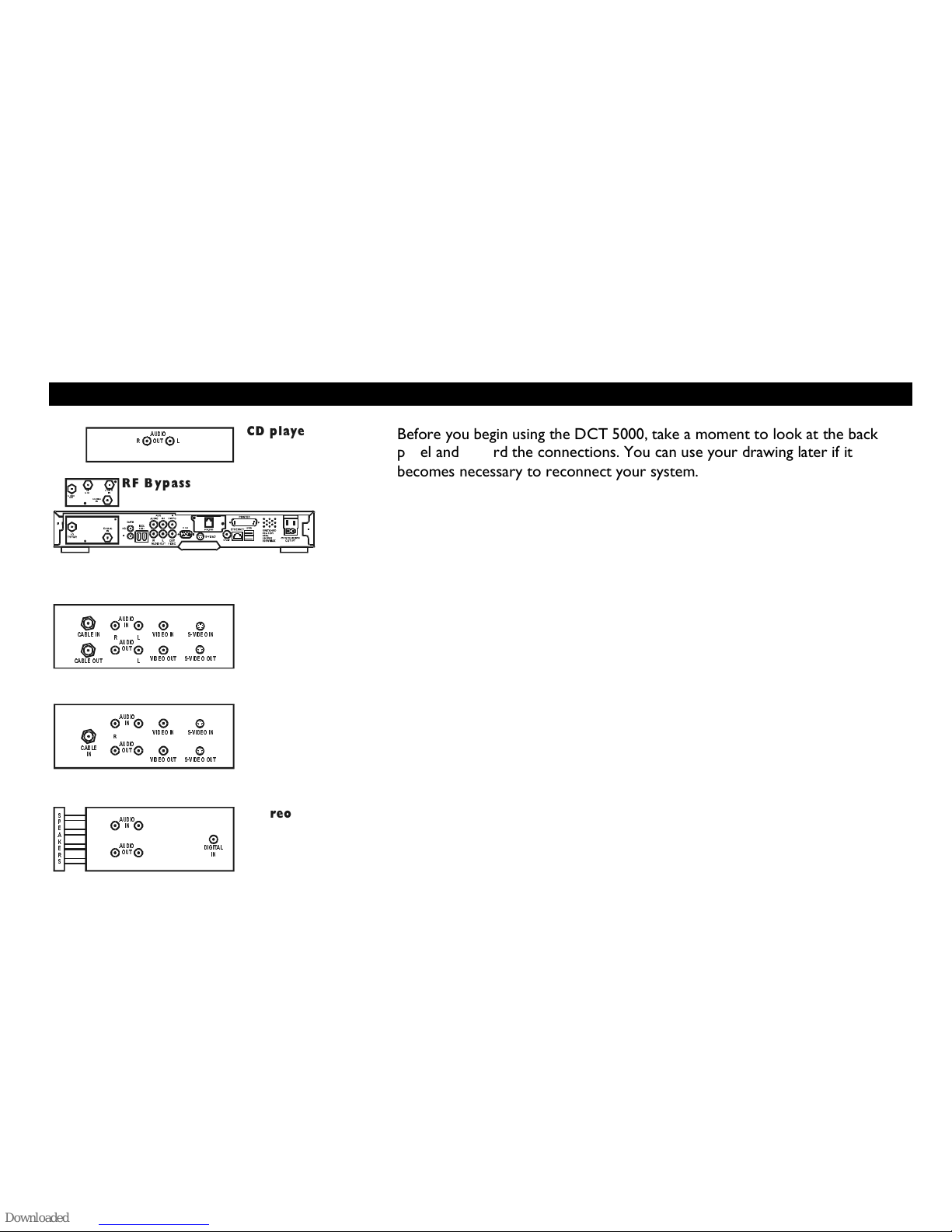
RECORDING YOUR CONNECTIONS
DCT 5000
9*$
63', )
CD player
$8',2
287
5/
VCR
&$%/(287
6
3
(
$
.
(
5
6
&$%/(
,1 9,'(2
,1 6 9 ,'(2
,1
69,'(2287
/5
9,'(2287
$8',2
287
/
TV
$8',2
,1
L
L
R
R
',*,7$/
,1
$8',2
287
$8',2
287
&$%/(
,1
$8',2
,1
$8',2
,1
69,'(2
,1
69,'(2287
9,'(2,1
9,'(2287
&219
28 7 &$%/(
,1
&219
,1
5)
287
RF Bypass
Stereo
Before you begin using the DCT 5000, take a moment to look at the back
panel and record the connections. You can use your drawing later if it
becomes necessary to reconnect your system.
8
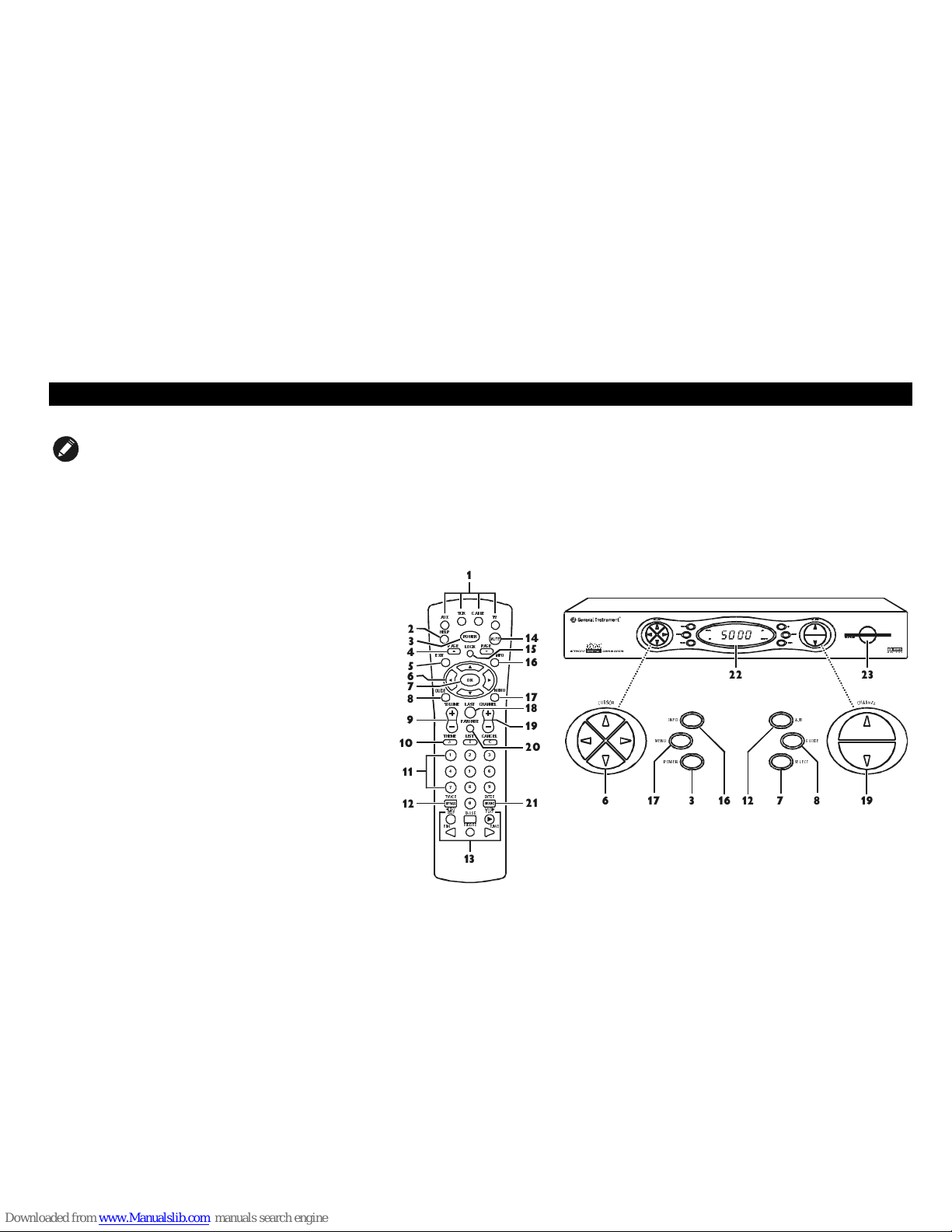
REMOTE CONTROL
NOTE
The remote control you receive may differ from the
remote control pictured here. Your service provider will
supply user instructions.
The DRC 400 provides basic control of the DCT 5000, TV, VCR, and
auxiliary devices such as a second TV or VCR. For programming instructions
refer to the instructions supplied by your service provider.
Notice that many of the keys on the front panel share the same function as
keys on the remote control.
,1)2 $ %
0(18 *8,'(
32:(5 6(/(&7
&
+
$
1
1
(
/
&
8
5
6
2
5
$8;
+(/3
/2 &.
3$*(
(;,7 ,1)2
0(18
3$*(
9&5 &$%/(
32:(5
79
2.
/$67
/,67
&+$11(/
&$ 1&( /
92/80(
7+(0(
$
799&5
5(:
6723
'$<
%
&
(17(5
) ):'
3$86(
5(&25'
3/$<
'$<
)$925,7(
,1752 $%
0(18 *8, '(
32:(56(/(&7
&
+
$
1
1
(
/
&
8
5
6
2
5
60$5 7
&$5'
3
087(
06*6
215(027(
$%
11
10
9
8
7
6
5
4
3
2
1
14
15
16
17
18
20
19
21 6 17 3 16 12 7 8 19
22 23
12
13

9
REMOTE CONTROL
Use this information with a basic electronic program guide. If your program guide is different, refer to the remote control
instructions.
Key Description
1AUX, VCR,
CABLE, OR TV
Selects a desired device to control. The selected mode will remain active until you press another key.
2HELP Displays the help screen.
3POWER Turns the selected home entertainment component on or off.
4PAGE
PAGE Pages through menu screens and the program guide.
5EXIT Exits a menu or program guide.
6
CURSOR Moves the cursor around the program guide and menu screens.
7OK/SELECT Selects menu options, pay-per-view events or tune programs from the program guide.
8GUIDE Displays the program guide.
9VOLUME +
VOLUME -
Increases or decreases the volume of the currently selected device.

10
REMOTE CONTROL
Key Description
10 A THEME
B LIST
C CANCEL
Functionality is determined from services offered by your service provider.
11 NUMBER KEYS Use to directly select a channel.
12 TV/VCR BYPASS
or A/B
Use to manually enable the RF bypass function. You must have a cable-ready TV for this function to operate.
13 STOP, PAUSE,
PLAY, REW.,
RECORD, F.FWD.
Controls the VCR.
14 MUTE Toggles the sound on and off.
15 LOCK/PPV Use to limit viewing of selected programs or to view the Pay-Per-View menu.
16 INFO Displays the current channel and program information (not supported by all applications).
17 MENU Displays the main menu.
18 LAST Recalls the last channel or goes back one screen in the menu.
19 CHANNEL +
CHANNEL -
Changes the channels by moving up or down.

11
REMOTE CONTROL
Key Description
20 FAVORITE Displays preset favorite cable channels.
21 ENTER/MUSIC Displays digital music channel menus. On some TV models press to enter channels.
22 LED Displays the channel number or time of day.
There are four indicator lights on the LED screen:
MSGS. — the DCT 5000 has received messages for you to read
ON — the DCT 5000 is powered on
A/B — the RF bypass is active
REMOTE — the remote control is in use
23 SMART
CARD SLOT
This interface is intended to support electronic commerce activity utilizing a smart card. Contact your service
provider for availability.
12
REMOTE CONTROL
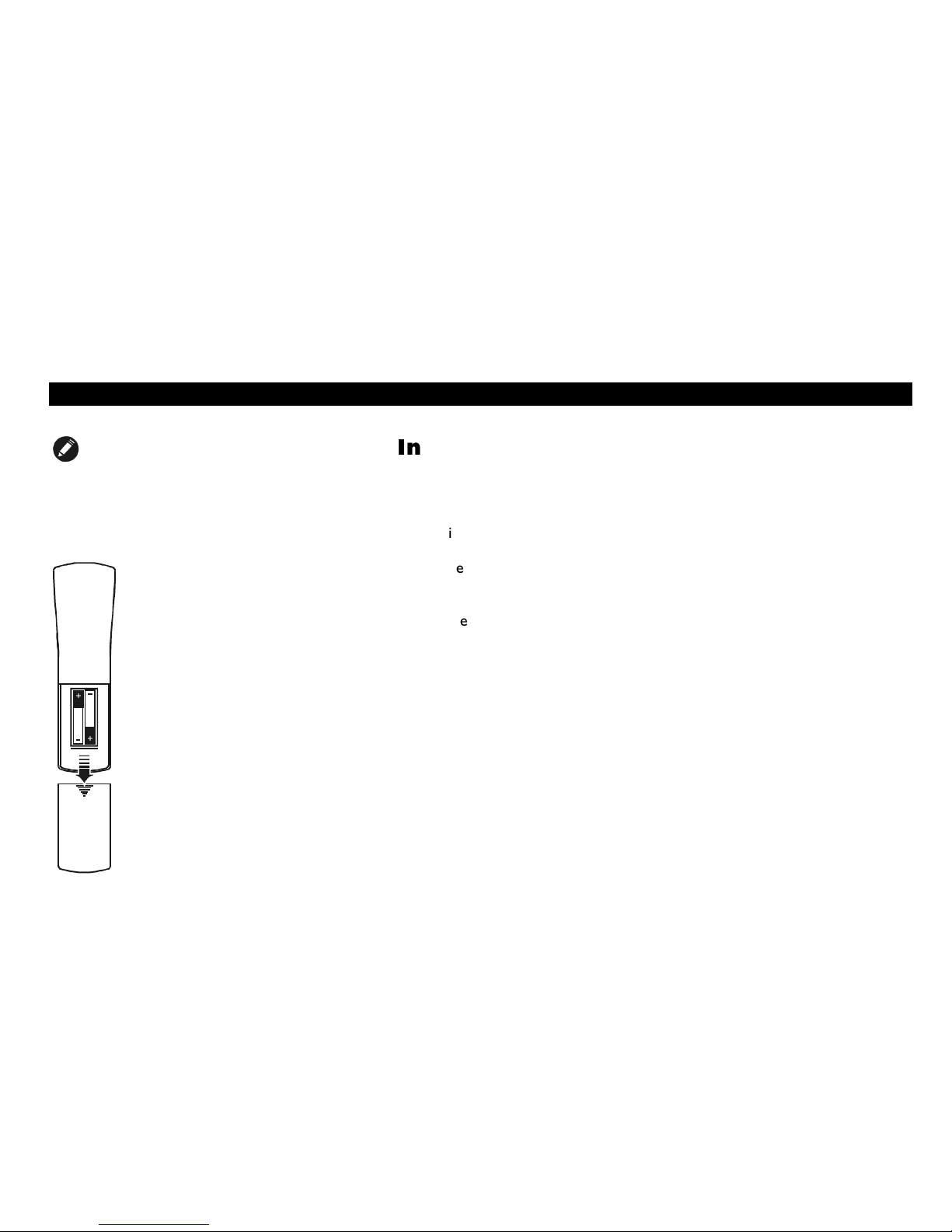
NOTE
Batteries installed incorrectly can cause battery
leakage and corrosion that will damage the remote
control
Installing Batteries
Before you can use the remote control, you must install two AA (1.5-volt)
alkaline batteries:
1
Slide open the battery door on the back of the remote control.
2
Insert the batteries in the direction indicated on the inside of the
battery compartment.
3
Slide the battery door closed until it snaps into place.
4
Point the remote control at the DCT 5000, press CABLE and then
press POWER. If the DCT 5000 does not turn on, check the orientation
of the batteries or replace with new batteries

13
BASIC OPERATION
NOTE
If the TO TV/VCR connector on the DCT 5000 is
connected to the coaxial CABLE IN connector on the TV,
you must tune your TV to channel 3 or channel 4.
Turning Power On and Off
Press POWER on the front panel, or press CABLE and then press POWER on
the remote control.
Changing Channels
You can change channels in two ways:
Press CHANNEL
or
on the front panel of the DCT 5000 or press
CHANNEL
or
on the remote control to step through the channel
selection.
Enter the number of the channel you want to tune using the numeric
keys on the remote control.
Adjusting the Volume
Press VOLUME
or
²
on the remote control to adjust the volume. When
you adjust the volume, the volume scale is displayed on the screen. Press
MUTE on the remote control to turn the sound off and on again.
For best audio quality, use the remote control to set the DCT 5000 to
approximately ¾ of maximum volume level and then adjust the audio levels
on the external devices.

14
AUDIO/VIDEO CONNECTIONS
NOTE
It is important to remember not to place anything on
top of the DCT 5000 and to provide for adequate
ventilation to prevent overheating.
Before you move or change components on your entertainment system,
review the following:
For basic cable connections, use 75-ohm coaxial cables equipped with
F-type connectors. (The coaxial connection will not provide stereo on
digital channels).
For audio or video outputs, use cables equipped with RCA-type
connectors.
Disconnect power from the DCT 5000 before moving it or changing
cable connections.
Do not place anything on top of the DCT 5000, especially other
home video components.
The DCT 5000 requires adequate ventilation and airflow during normal
operation to prevent overheating.

15
AUDIO/VIDEO CONNECTIONS
RF Bypass Switch
The DCT 5000 may be equipped with the optional RF Bypass switch.
When the optional RF bypass switch is activated it routes the cable signal
directly to a cable-ready TV, bypassing the DCT 5000. This configuration
enables you to view clear analog programming on the direct cable signal
should the DCT 5000 be powered off.
9*$
63',)
&219
287 &$%/(
,1
&219
,1
5)
287
From cable outlet
RF Bypass
To T V
16
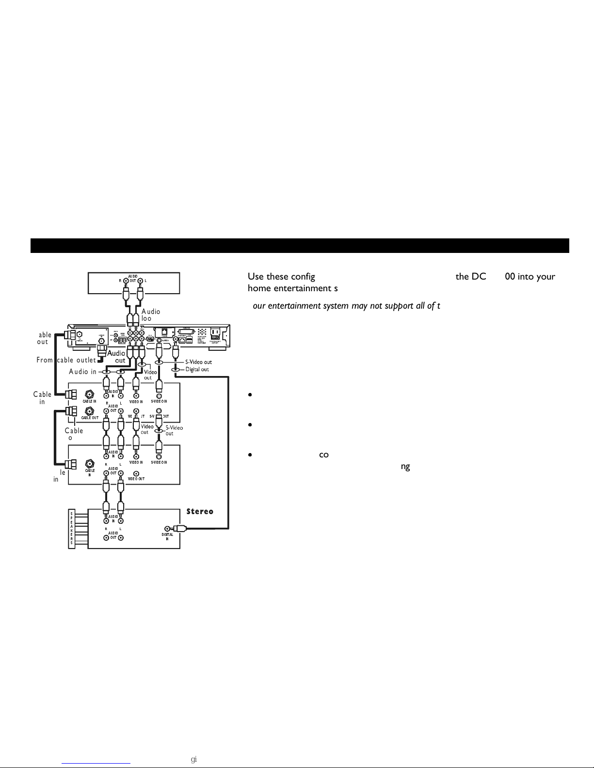
AUDIO/VIDEO CONNECTIONS
DCT 5000
9*$
63', )
Audio
loop-thru
Audio out
CD player
$8',2
287
5
/
VCR
&$%/(287
&$%/(
,1 9,'(2
,1
69,'(2,1
69,'(2287
/5
9,'(2
287
$8',2
287
/
TV
Cable
in
Cable
out
Cable
out
Audio in
$8',2
,1
L
L
R
R
',*,7$/
,1
$8',2
287
$8',2
287
&$%/(
,1
Cable
in
$8',2
,1
$8',2
,1
69,'(2,1
9,'(2,1
9,'(2
287
6
3
(
$
.
(
5
6
Stereo
From cable outlet
Use these configurations as aides when connecting the DCT 5000 into your
home entertainment system.
Your entertainment system may not support all of these connections.
This drawing illustrates audio/video connections with a stereo at the end of
the chain. Use this connection to view your TV with sound coming through
your stereo system. An advantage to this connection is that you use one set
of RCA input connectors on your stereo.
It is important to remember:
The channel 3 and 4 coaxial cable connection does not carry stereo
for digital channels.
The RCA audio connections carry stereo for both analog and digital
channels.
The SPDIF connection is capable of passing through Dolby Digital 5.1
audio for those programs offering Dolby Digital content.
Table of contents
Other Seaside Cable Box manuals


