SeasonsComfort Morillo 32101 User manual

Owner’s Manual
Parts # 269606, 269608, 269610
Models # 32101, 32099, 32100
1
Morillo™ 52” LED
Ceiling Fan
If you are experiencing diculty in installation, please
contact Customer Service: 1-800-431-3000.
Exclusively Distributed by:
HD Supply Facilities Maintenance, Ltd.
Atlanta, GA 30339
Made in China
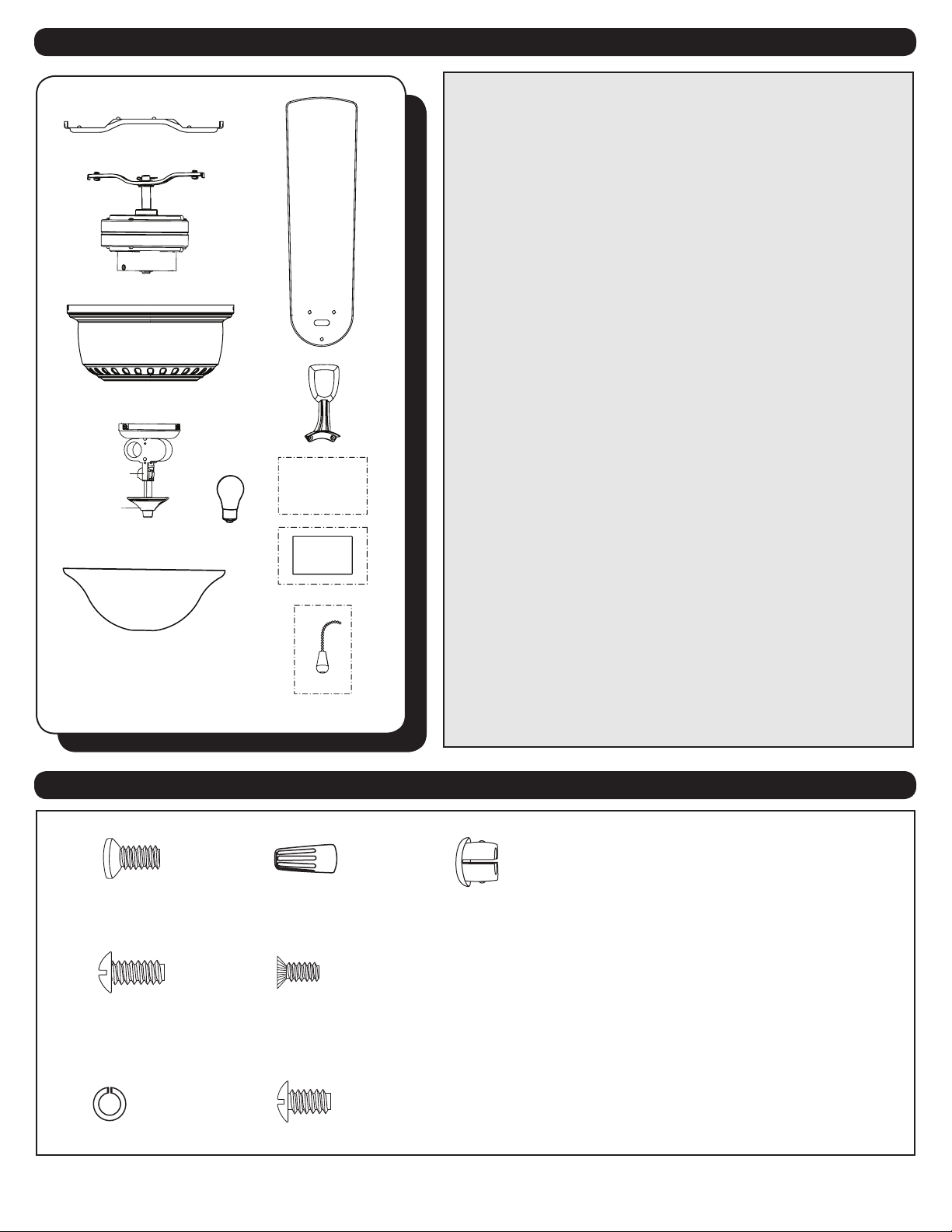
PACKAGE CONTENTS
2
HARDWARE CONTENTS
18
19 22
23
21
20
1. Mounting Bracket
2. Lower Bracket
3. Motor
4. Switch Housing
5. Motor Housing
8. Finial Cap
9. Finial
10. Bulb (x 2)
11. Glass Bowl
12. Blade (x 5)
13. Blade Arm (x 5)
15. Installation Instructions
18. Bracket Screw (x 4)
19. Lock Washer (x 4)
20. Wire Connector (x 3)
21. Switch Housing Screw (x 3)
22. Mounting Screw (x 4)
Unpack your fan and check the contents. You should
have the following items:
PACKAGE CONTENTS
HARDWARE CONTENTS
Note: Some extra hardware has been included. The quantity
listed above is the number required for installation.
14
15
16
1
2
3
4
6
5
8
7
9
10
11
13
12
Installation
Instructions
Hardware Kit

3
Mounting Bracket
Switch Housing Cap
Lower Bracket
Motor Housing
Motor
Switch Housing
Bulb
Glass Bowl
Finial Cap Finial
Blade
Blade Arm
EXPLODED VIEW DETAIL
3
DIMENSION REFERENCE
D
B
A
C
4
WARNING:
READ ALL SAFETY INFORMATION AND INSTALLATION INSTRUCTIONS BEFORE YOU BEGIN INSTALLING THE
FAN AND SAVE INSTRUCTIONS.
All set screws of the fan must be checked and retightened where necessary before installation.
To reduce the risk of personal injury, do not bend the blade brackets when installing the brackets, balancing
the blades or cleaning fan. Do not insert foreign objects in between rotating fan blades.
Before changing the fan direction, turn o the fan and wait for the fan blades to stop completely.
If a stationary appliance is not provided with a supply cord and a plug, or with other means for
disconnection from the main supply having a contact separation of at least 3 mm in all poles, that means for
disconnection must be incorporated in the xed wiring in accordance with the wiring rules.
The safeguards provided by these safety instructions and by the separate installation instructions are not
meant to cover all possible conditions and situations that may occur. It must be understood that common
sense, caution and care are factors which can not be built into this product. These factors must be supplied
by the person(s) installing, caring for and operating the fan.
The fan weight is
to the building structure and is marked “Acceptable For Fan Support”. Failure to do so can result in serious
injury.
This equipment has been tested and found to comply with the limits for a Class B digital device, pursuant
interference in a residential installation. This equipment generates, uses and can radiate radio frequency
energy and, if not installed and used in accordance with the instructions, may cause harmful interference
to radio communications. However, there is no guarantee that interference will not occur in a particular
installation. If this equipment does cause harmful interference to radio or television reception, which can be
determined by turning the equipment o and on, the user is encouraged to try to correct the interference by
one or more of the following measures:
--Reorient or relocate the receiving antenna.
--Increase the separation between the equipment and receiver
--Connect the equipment into and outlet on a circuit dierent from that to which the receiver is connected.
--Consult the dealer or an experienced radio/TV technician for help.
void the user’s authority to operate the equipment.
To avoid risk of electric shock, be sure to shut o power at the main fuse or circuit breaker box before
installing or servicing this xture. Turning o the electrical power by using the light switch is not
sucient to prevent electrical shock.
oor and at least 18 inches (0.5 Meters) from the tip of the blades to the wall.
To reduce the risk of re, electric shock, or personal injury, mount to outlet box marked “acceptable for
fan support” and use mounting screws provided with the outlet box.
codes. If you are unfamiliar with the methods of installing electrical wiring, seek the services of a
qualied licensed electrician.
SAFETY INSTRUCTIONS
CAUTION:
5
ASSEMBLY INSTRUCTIONS
Lower Bracket
Bracket Screw
Mounting Bracket
Hook
Slots
Outlet Box
Hanger
Bracket
3
2
1
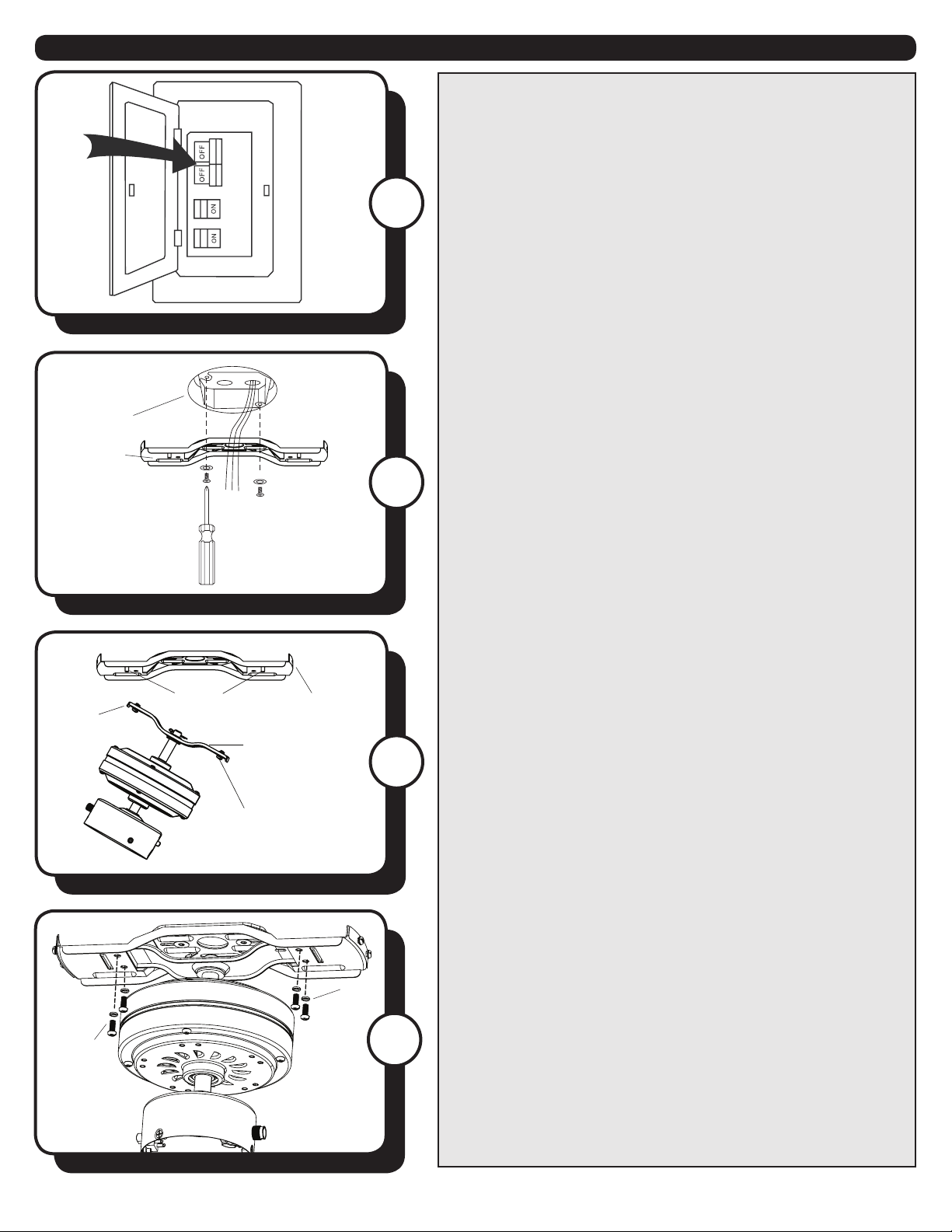
1. Turn OFF the electrical power at the main fuse or circuit
breaker.
2. Secure the mounting bracket to the outlet box (not
included) using the two mounting screws supplied with
outlet box and the at washers from the hardware bag.
Warning: To reduce the risk of re, electrical shock, or
personal injury, mount the fan to the outlet box marked
“acceptable for fan support”.
Note: Remove the wire restraint from the wires on top of
the lower bracket.
3. Remove the pre-assembled bracket screws from the
lower bracket. Insert the hook from one side of the lower
bracket into the slot of the mounting bracket. Then insert
the other side of the lower bracket into the second slot in
the mounting bracket until the four mounting screw holes
are aligned.
4
4. Secure the lower bracket to the mounting bracket with
the four bracket screws.
Bracket
Screws
Lock
Washer

6
ASSEMBLY INSTRUCTIONS
Black (live)
White (neutral)
Bare/Green (ground)
Black
Blue
White
Green
7
6
5
bracket to determine which two mounting screws in
the sides of the mounting bracket align with the J-slots
the two mounting screws that align with the J-slots.
Remove the other two mounting screws from opposite
sides of the mounting bracket. Lift the motor housing
over the motor aligning the J-slots in the motor housing
with the loosened mounting screws in the mounting
bracket. Twist the motor housing clockwise to lock. Then
re-insert the two previously removed mounting screws
and tighten all four mounting screws.
lock to secure the blade.
Repeat for the remaining blades and blade arms.
8
8. Secure the blade arm to the underneath side of the
motor using the previously removed motor screws.
Completely secure each blade arm to motor before
moving to the next.
To install the fan without the light kit, skip to Step 16.
Motor Screw Blade
Arm
Blade
Blade
Arm
Blade
Lock
Mounting
Screw
Mounting
Bracket
J-Slot
Motor
Housing
5. Use wire connectors to connect the fan wires to the
power supply wires according to the wiring diagram and
the following instructions:
bare/green (ground) supply wire.
(neutral/common) supply wire.
black (live/hot) supply wire.
Note: If there is a second hot/power wire coming from
the outlet box, connect it to the Blue (light power) fan
wire for separate light and fan control.
Important: After the connections have been made, the
connected wires should be turned upward and pushed
wire connections on opposite sides of the outlet box.
Wire Connector

7
ASSEMBLY INSTRUCTIONS
11
10
9
9. Remove the switch housing screws that were
pre-assembled to the switch housing cap at the top of the
light kit. Then, connect the single-pin connectors from the
fan to the single pin connectors from the light kit -- blue to
black and white to white.
10. Secure the light kit to the switch housing using the
three previously removed switch housing screws. Then,
remove the nial and nial cap from the bottom of the
light kit.
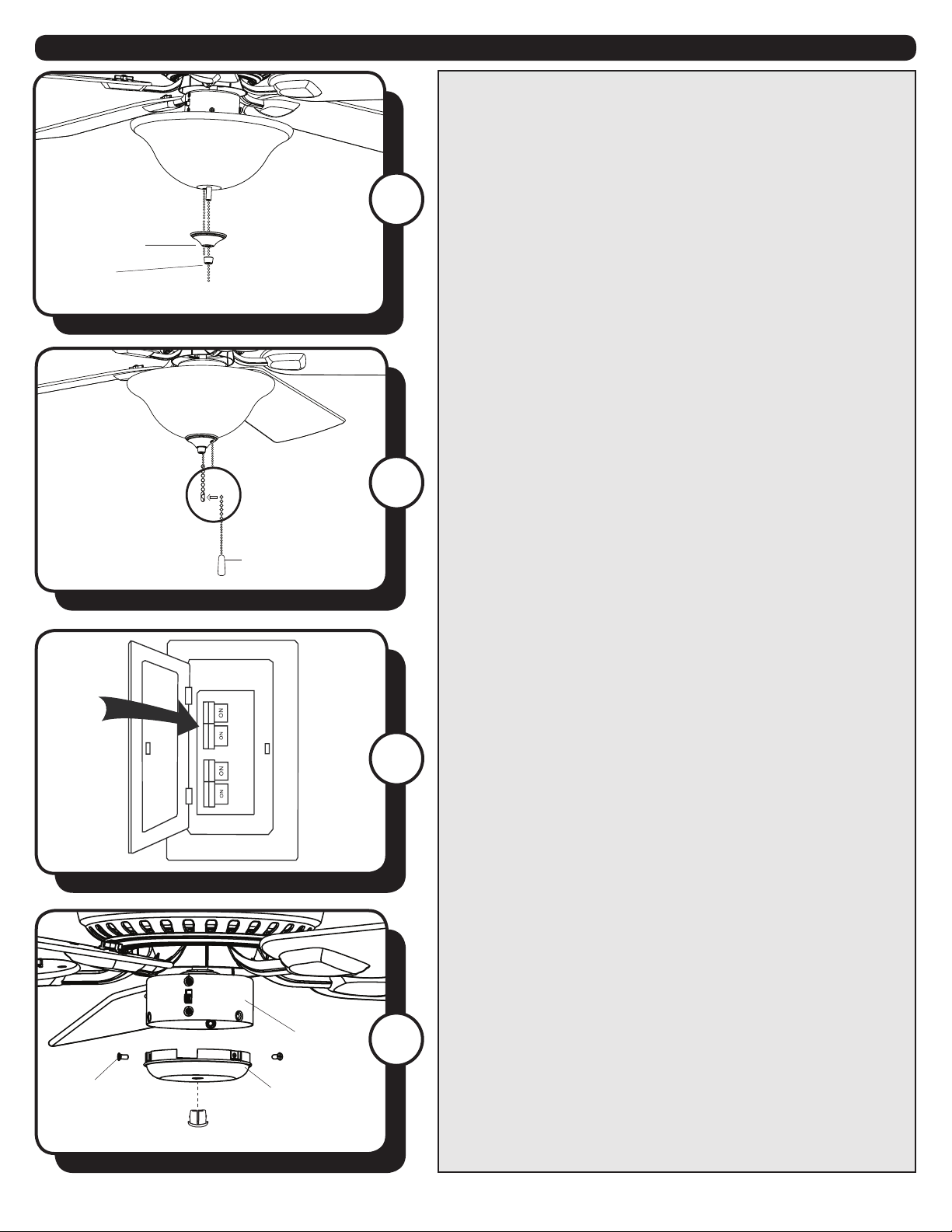
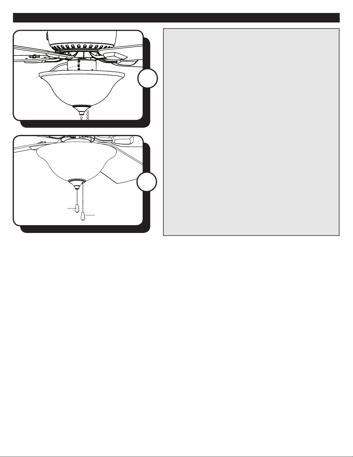
11. Feed fan pull chain coming from the switch housing
down through the grommet in the lower part of the light
sockets of the light kit.
12. Feed the pull chain coming from the grommet in the
light kit through the o-center hole in the glass bowl.
Feed the pull chain coming from the center of the light
kit through the center hole in the glass bowl. Then, lift
the glass bowl onto the threaded rod at the bottom of
the light kit.
12
Switch
Housing
Screw
Switch Housing
Glass Bowl
Finial Cap
Finial
Switch
Housing Cap
Switch
Housing Cap
Single-pin
Connector
Switch
Housing
Screws
Grommet
Bulb
ASSEMBLY INSTRUCTIONS
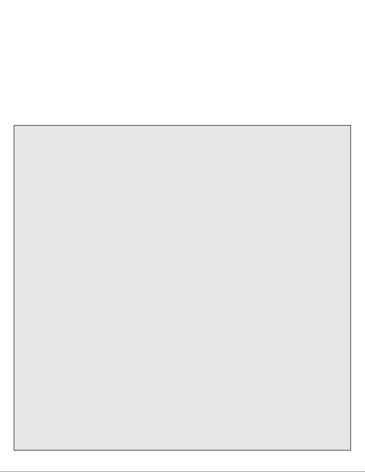
14
14. Attach the pull chain extensions to the fan and light
pull chains.
15. Restore the power at the main fuse or circuit breaker.
13. Feed the pull chain through the appropriate holes
in the nial cap and the nial. Lift the nial cap up until
it is ush with the glass bowl. Screw the nial onto the
threaded rod of the light kit to secure the glass bowl.
Finial Cap
Finial
13
15
Switch
Housing Cap
Switch
Housing
Screw
Switch
Housing 16
NO LIGHT KIT OPTION
a. Remove the switch housing screws from the switch
housing cap at the top of the light kit.
b. Remove the light kit from the switch housing cap by
removing the hex nut and washer from inside the switch
housing cap.
c. Insert plug button into center of switch housing cap.
d. Install the switch housing cap to the bottom of the
switch housing with the three switch housing screws.
e. Attach the pull chains extension (Step 14).
f. Restore the power at the main fuse or circuit breaker.
8
9
OPERATING INSTRUCTIONS
1
2. The fan pull chain has four positions to control the fan
speed. One pull is HIGH, two is MEDIUM, three is LOW,
and four turns the fan OFF.
The light pull chain has two positions to control the light,
ON and OFF.
2
1. Use the fan reverse switch, located on the switch
housing to optimize your fan for seasonal performance.
Using a ceiling fan will allow you to raise your thermostat
setting in summer and lower your thermostat setting in
winter without feeling a dierence in your comfort.
Note: Wait for the fan to stop before moving the reverse
switch.
In warmer weather, push the reverse switch down which
will result in downward airow creating a wind chill eect.
In cooler weather, push the reverse switch up, which will
result in upward airow that can help move stagnant, hot
air o the ceiling area.
Reverse
Switch
Chain
Chain

10
PROBLEM SUGGESTED REMEDY
TROUBLESHOOTING
1. Fan does not start 1. Check main and branch circuit fuses or circuit breakers.
2. Check power supply wire connections to fan and switch wire connections in switch
housing.
CAUTION: Make sure main power is turned o.
3. Make sure forward/reverse switch pushed completely up or down. Fan will not operate
when switch is in the middle.
4. Make sure that the wall control is turned ON.
1. Make sure all screws in motor housing are snug, but not overtightened.
2. Make sure the screws which attach the blade arm to the motor are tight.
3. Make sure wire connectors in switch housing are not rattling against each other or
against the interior wall of the switch housing.
CAUTION: Make sure main power is turned o before entering switch housing.
4. If using a light kit, be sure the glass shades are nger tight. Check to be sure light bulb are
snug in sockets and not touching glass shade(s). If vibration persists from glass, remove
glass and install a 1/4 in. wide rubber band on glass neck to act as an insulator. Replace
glass and tighten screws against rubber band.
5. Some fan motors are sensitive to signals from Solid State variable speed controls. DO NOT
USE a Solid State variable speed control.
1. Ensure all blades are screwed rmly into blade arms.
2. Ensure all blade arms are tightened securely to motor.
3. Ensure canopy and mounting bracket are tightened securely to outlet box and outlet box
is mounted rmly to ceiling joist.
4. Switch one blade with a blade from the opposite side. Or balance the fan using a
balancing kit.
5. If blade wobble is still noticeable, interchanging two adjacent (side by side) blades can
redistribute the weight and possibly result in smoother operation.
1. Ensure the single pin connectors from the switch housing are rmly connected to the
single pin connectors from the light kit -- black to blue and white to white.
2. Check for loose or disconnected wires in fan switch housing.
3. Check for loose or disconnected wires in light kit.
4. Check for faulty light bulbs.
CAUTION: Make sure main power is turned o before entering switch housing.
2. Fan is noisy
3. Fan wobbles
4. Light does not work:
If you have diculty operating your new ceiling fan, it may be the result of incorrect assembly, installation or
wiring. In some cases, these installation errors may be mistaken for defects. If you experience any faults, please
check the Troubleshooting section below. If a problem cannot be remedied or you are experiencing diculty in
installation, please contact Customer Service: 1-800-431-3000.
LIMITED LIFETIME WARRANTY
Model Name: Seasons® Morillo™ 52” LED Ceiling Fan
Model No: 32099 - Brushed Nickel
32100 - Sienna
32101 - White
11
the fan motor for this ceiling fan to be free from defects in workmanship and material for the life of
excludes the motor and parts made in whole or in part with glass) to be free from defects in workmanship
and material for a period of one year after the date of purchase by the original purchaser at retail.
All claims must be made by the original purchaser, whether such purchaser purchased the product through a
store or contractor. Ceiling fan part defects must be reported within the rst year from the date of purchase.
part caused by ordinary wear and tear, accident, misuse, or improper installation, is not covered by this
licensed electrician will render the warranty invalid.
damages resulting directly or indirectly, from any breach of warranty, express or implied, or any other
failure of this product. Some states do not allow the exclusion or limitation of incidental or consequential
damages so this limitation may not apply to you.
If the original purchaser ceases to own the fan, this warranty is voided.
Should the purchaser encounter a problem with your fan related to defects in workmanship or materials
without charge, or at its option, to replace the ceiling fan with a comparable or superior model.
ceiling fan limited lifetime
warranty. All other express and implied warranties, including, without limitation, the implied warranty of
tness for a particular purpose and the implied warranty of merchantability are disclaimed. Some states do
not allow the disclaimer of implied warranties, so this disclaimer may not apply to you.
To obtain warranty service, please write down your model number and call Customer Service
To obtain Service, please contact Customer Service: 1-800-431-3000.
This manual suits for next models
5
Table of contents
Other SeasonsComfort Fan manuals


Popular Fan manuals by other brands


Mitsubishi Electric
Mitsubishi Electric CITY MULTI PLFY-EP06NEMU-E Technical & service manual

Casablanca
Casablanca Brescia Owner's guide and installation manual

Atlas fan company
Atlas fan company Irene-3H instructions

Flexit
Flexit Eq 2 Assembly and operation instructions

Broan
Broan QTXE150FLT instruction manual

Premier
Premier AB-4104BX instruction manual


