SEBA SEBAPuls User manual

User manual
Version 3.01
SEBAPuls
Product code: RAD 580X
English
SEBA HYDROMETRIE GmbH & Co. KG
Gewerbestrasse 61 a
87600 Kaufbeuren
Germany
Tel. (+49) 8341 9648-0
Fax (+49) 8341 964848
E-Mail: [email protected]
www.seba.de

Technical changes and errors reserved!

Content
1INTENDED USE ..........................................................................................- 4 -
2PRODUCT DESCRIPTION ............................................................................- 4 -
3SAFETY AND DANGER INSTRUCTIONS........................................................- 5 -
4MOUNTING ...............................................................................................- 6 -
4.1 Mounting variants............................................................................................................................................. - 6 -
4.2 Mounting example............................................................................................................................................ - 8 -
4.3 Reference plane and antenna edge .................................................................................................................. - 9 -
4.4 Positioning the SEBAPuls ................................................................................................................................ - 10 -
4.5 Analog signal output (4-20 mA / 0.2-1V / 0.4-2V) .......................................................................................... - 11 -
4.5.1 Connecting SEBAPuls with analog output (with DC/DC converter) ............................................................. - 11 -
4.5.2 Connecting SEBAPuls with analog output (without DC/DC converter)........................................................ - 12 -
4.6 Digital signal output (SDI-12) .......................................................................................................................... - 13 -
4.6.1 Settings via SDI-12 protocol ......................................................................................................................... - 13 -
4.6.2 Measurement value output ......................................................................................................................... - 13 -
4.6.3 Connecting SEBAPuls 8 / 15 with SDI-12 output.......................................................................................... - 14 -
4.6.4 Connecting SEBAPuls 20 / 120 with SDI-12 output...................................................................................... - 15 -
5PUTTING INTO OPERATION .....................................................................- 16 -
5.1 SEBAPuls with analog output.......................................................................................................................... - 16 -
5.2 SEBAPuls with SDI-12 output .......................................................................................................................... - 16 -
6POWER SUPPLY .......................................................................................- 17 -
7MAINTENANCE........................................................................................- 17 -
8TECHNICAL DATA.....................................................................................- 18 -
9ACCESSORIES...........................................................................................- 18 -
10 DISPOSAL ................................................................................................- 19 -

Chapter 1
4
1INTENDED USE
The radar sensor SEBAPuls is solely used for non-contact measurement of water level in rivers,
channels, dams, lakes or tidal areas.
Consider the technical specifications in chapter 8 when using the device.
Solely the use in accordance with the instructions described in this user manual is an intended use.
Any other use is not an intended use of this device.
2PRODUCT DESCRIPTION
The radar sensor SEBAPULS is a high accuracy measuring device measuring the surface water level
without direct contact. Therefore the radar measurement is unaffected by mudding, drifting
materials, weed, sewage and brackish or saline water etc.
There is no influence in the measurement accuracy caused by air humidity (fog) or air temperature
fluctuations. Further advantages implementing this radar sensor are the low energy consumption,
the short measuring cycle and the short mounting distance.
The measuring principle, the so called pulse procedure, sends a short microwave impulse to the
water surface. Subsequently the transmitter has a short time lag. Within this time lag, it receives the
reflected impulse from the water surface and transmits it to the integrated evaluation system. The
run time of the impulses corresponds directly to the distance of the actual surface water level.
SEBAPuls 8
SEBAPuls 15
SEBAPuls 20
SEBAPuls 120

Chapter 3
5
3SAFETY AND DANGER INSTRUCTIONS
General
▪Read the user manual carefully before starting with operation!
▪Only use the device as intended and described in this user manual!
▪Always keep the user manual available at site where the device is used!
▪Keep the user manual for future operation!
▪In case you sell the device or hand it to someone else, also hand over the user manual!
▪Please be informed that operation and connection faults are beyond our sphere of influence. So,
understandably, we cannot take over liability for resulting damages.
Marks
Pay attention to the different marks used in this user manual.
See hereafter the explanation of meanings of the used marks.
Warning: Situation that might result in injury or death.
Attention: Situation that might result in damage to the device.
Important notice: Important notice and additional information.
Working with electrical voltage
By handling devices, which are supplied by electrical voltage, the valid VDE-instructions, especially
VDE 0100, VDE 0550 und VDE 0700 have to be considered.
Before opening an instrument, pull off the mains plug (if existing) and make sure that the instrument
is without power supply.
Parts, construction groups or instruments must only be set into operation, in case they are built into
a housing and protected against touching. During installation they have to be without power.
It is only allowed to use tools at the instruments, parts or construction groups, in case it is secured
that the instruments are dropped out and the electric loads which are stored in the construction
groups inside the instrument, are unloaded.
Conducting cables or conductors, which are connected to the instrument, part or construction group,
have to be checked continuously to isolation faults or sites of fractures. By verification of a fault in
the supply cable, the instrument has to be switched-off immediately, until the defect cable has been
exchanged.
Before setting into operation, generally check if the instrument or construction group is suitable for
the field of application. In case of doubts, unconditionally contact specialists, experts or the
manufacturer of the used construction group!

Chapter 4
6
4MOUNTING
4.1 Mounting variants
Mounting with locknut
The types SEBAPuls 8 and 15 can be mounted on the SEBA standard boom with opening for thread
G 11/2 by means of the locknut. Push the sensor into the opening of the boom and fix it with the
enclosed locknut.
For the distance to the wall, refer to chapter 4.4.
SEBAPuls 8 SEBAPuls 15
mounted to SEBA standard boom mounted to SEBA standard boom
with lock nut with lock nut
SEBA standard boom
Chapter 4
7
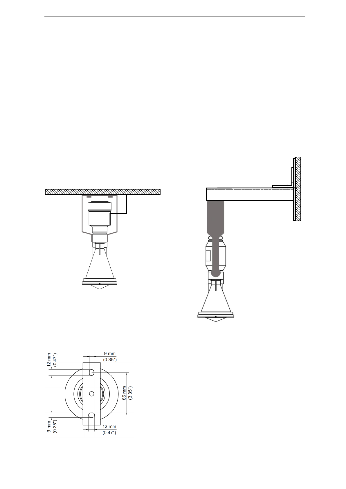
Mounting with mounting strap
The types SEBAPuls 15, 20 and 120 can be mounted using a mounting strap. First attach the
mounting strap to the desired position and then attach the radar sensor to the mounting strap
using the screws provided.
The mounting strap is optional for the SEBApuls 15 and included in the standard scope of delivery
for the SEBAPuls 20 and 120 types.
The mounting strap can be attached both to the SEBA standard boom and directly to ceilings or
walls.
For the distance to the wall, refer to chapter 4.4.
SEBAPuls 20 / 120 SEBAPuls 15
Ceiling mounting with mounting strap mounted to SEBA standard boom
with mounting strap
Top view of mounting strap

Chapter 4
8
4.2 Mounting example
Wall
Radar sensor
SEBAPuls 15
SEBA standard boom
510 mm
connection box
0m distance to water surface
= 20mA output
15m distance to water surface
= 4mA output

Chapter 4
9
4.3 Reference plane and antenna edge
The reference plane (1) marks the zero point of the measuring range of each sensor.
The minimum distance to the water surface is measured from the end of the antenna (2) on the
sensor. The following minimum distances to the water surface apply to the various sensor types:
* Individual setting possible, sensor needs to be sent to SEBA.
(1) Reference plane
(2) Antenna edge
Model
Minimum distance to water surface*
(measured from antenna edge)
SEBAPuls 8
5 cm, factory setting 0,5 m
SEBAPuls 15
5 cm, factory setting 1 m
SEBAPuls 20
5 cm, factory setting 1 m
SEBAPuls 120
25 cm, factory setting 1 m
SEBAPuls 8
SEBAPuls 20 / 120
1
2
SEBAPuls 15
Chapter 4
10
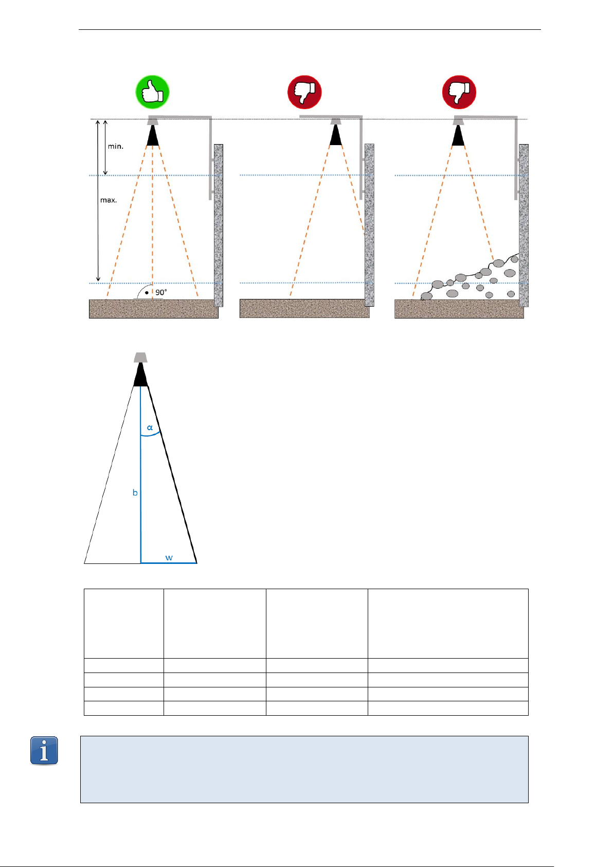
4.4 Positioning the SEBAPuls
Formula to calculate minimum distance to wall/shore/etc.
w= tan α*b
α= radiation angle
b= measuring range
w= radiation radius (minimum distance to wall/shore/etc.
Model
Radiation
angle
α
Measuring range
b
Radiation radius (minimum
distance to wall/shore)
w
SEBAPuls 8
10°
8 m
1.41 m
SEBAPuls 15
5°
15 m
1.31 m
SEBAPuls 20
5°
35 m
3.06 m
SEBAPuls 120
3.5°
120 m
7.34 m
Important notice
Pay attention to the vertical installation of the sensor shaft to the measuring medium because
otherwise the echoes are reflected into wrong directions and cannot be received by the
antenna.
Reference plane

Chapter 4
11
4.5 Analog signal output (4-20 mA / 0.2-1V / 0.4-2V)
The analog signal output of SEBAPuls is available in three different versions.
The output version is marked on the label of the DC/DC converter.
4.5.1 Connecting SEBAPuls with analog output (with DC/DC converter)
The system can be switched on by applying a voltage between 2V and 30V to the switch input. This
makes sure that energy will be consumed only during the measurement. For permanent operation
the switch can be put ON.
Example: Type 12V/24V
with output 4…20mA
Example: Type 24V/24V
with output 0.4…2V
Radar sensor
+ enable 2…30V
Switch ON= Continuous operation
Switch OFF= Cycle operation
battery + 12V
input + radar sensor
output –meas. value
input - radar sensor
- battery
output + meas. value
ground
4...20mA, 0.2…1V
or 0.4…2V
Grounding
To application
ON
OFF
(voltage or current output)
brown= +Sensor
black= -Sensor
DC/DC converter
Connection box
ON
ON

Chapter 4
12
4.5.2 Connecting SEBAPuls with analog output (without DC/DC converter)
The DC/DC converter is not required for the following data loggers:
▪Unilog
▪UnilogCom (where the cable length of the radar sensor is <200 m)
Important notice
More information is available in the operating instructions regarding connecting the respective
data logger and/or in the connection diagram supplied with your shipment.

Chapter 4
13
4.6 Digital signal output (SDI-12)
All SEBAPuls sensors can be equipped with a digital SDI-12 output instead of the standard analog
output.
4.6.1 Settings via SDI-12 protocol
The sensor address of SEBAPuls can be changed by the following commands of the SDI-12 protocol:
Command
Response
aAb!
a –the sensor address
A –the change address command
b –address to change to
! –terminates the command
b<CR><LF>
b –the address of the sensor (will equal the new
address or the original address if the sensor is
unable to change the address)
<CR><LF> - terminates the response
4.6.2 Measurement value output
4.6.2.1 Start measurement command
The SEBAPuls supports the following start measurement command:
aM! (resp. aMC! with checksum)
With the aM! –command the measurement of channel 1 is started. As a response the sensor sends,
in addition to the number of available channels, a hold-back time after which the measured values
are available. If measured values are earlier available a Service Request can be sent so the collecting
of data will happen faster.
Collecting the measurement values:
Collecting the measurement values is done by the aD0! command, whereas aD0! corresponds to
channel 1.
4.6.2.2 Concurrent measurement
Furthermore it is possible to start measurement of all channels concurrently by the aC! command.
aC! (resp. aCC! with checksum)
With the aC! –command the measurement of channel 1 is started. As a response the sensor sends,
in addition to the number of available channels, a hold-back time after which the measured values
are available. If measured values are earlier available a Service Request can be sent so the collecting
of data will happen faster.
Collecting the measurement values:
Collecting the measurement values is done by the aD0! command, whereas aD0! corresponds to
channel 1.

Chapter 4
14
4.6.3 Connecting SEBAPuls 8 / 15 with SDI-12 output
The SEBAPuls 8 / 15 with SDI-12 output is delivered with an external SDI-12 converter, which can be
mounted to mounting rails. The connection of the converter has to be performed as follows:
Radar sensor
SDI-12
To application
Clamp 9: blue = -Sensor
Clamp 10: brown = +Sensor
SDI-12 converter
Connection box
Clamp 1: Ground
Clamp 4: +12V
Clamp 5: SDI Data

Chapter 4
15
4.6.4 Connecting SEBAPuls 20 / 120 with SDI-12 output
The SDI-12 output of the sensors SEBAPuls 20 / 120 is provided directly without converter. The wiring
of the sensor has to be performed according to the following terminal assignment:
Depending on the configuration of the data logger, you can connect SDI-12 sensors either with a
M12-plug or wire them on a mounting rail with terminal strip, provided that the data logger has a
SDI-12 sensor input.
In case you connect the SDI-12 sensor with a M12-plug to the data logger, consider the following pin
assignment for mounting the plug to the sensor, if this has not been prepared at the factory.
In case you wire the SDI-12 sensor on a mounting rail with terminal strip, additionally consider the
wiring diagram included in delivery.
Radar sensor
Grounding
Connection box
Function Color
SDI Data: Red
Ground: Black
+12V: Brown
Back side
of M12-plug
Pin 1 GND: Shared ground connection between
data logger and sensor
Pin 2 DATA: SDI-12 data (bidirectional)
Pin 3 +Supply: SDI-12 supply
Pin 4 not allocated

Chapter 5
16
5PUTTING INTO OPERATION
5.1 SEBAPuls with analog output
▪Perform wiring according to the scheme in chapter 4.5.1
The DC/DC converter should be mounted close to the data logger –not close to the radar sensor.
▪The connection clamps of the DC/DC converter are screw-less. Press a small screwdriver into the
small opening. Then insert the wire to be connected and remove the screwdriver. Proceed with
each contact of the connector. The wire may be used with core sleeve at its end or simply
insulation-stripped
▪Connect the grounding screw (not applicable for SEBAPuls 8 / 15) at the bottom of the sensor
housing to a proper grounding next to the sensor with a wire of at least 4 mm².
▪The instrument is switched on by applying operation voltage. The first valid measured value
depends on the lead time of the sensor (hence on sensor type):
Lead times:
SEBAPuls 8: 55 seconds
SEBAPuls 15: 55 seconds
SEBAPuls 20: 55 seconds
SEBAPuls 120: 55 seconds
▪During the initialization, resp. if no echo is recognized; there is a 22mA fault current signal or a
2.2V fault voltage signal.
5.2 SEBAPuls with SDI-12 output
▪Perform wiring of SEBAPuls 8 / 15 according to the scheme in chapter 4.6.3 and for the types
SEBAPuls 20 / 120 according to the scheme in chapter 4.6.4.
▪The connection clamps of the SDI-12 converter of SEBAPuls 8 / 15 are with screws. Open the screw
of the respective clamp. Insert the wire to be connected and tighten the screw again. Proceed
with each contact of the connector. The wire may be used with core sleeve at its end or simply
insulation-stripped.
▪Connect the grounding screw (not applicable for SEBAPuls 8 / 15) at the bottom of the sensor
housing to a proper grounding next to the sensor with a wire of at least 4 mm².

Chapter 6
17
6POWER SUPPLY
Analog version:
12VDC (with DC/DC converter Type 12V/24V) or
24VDC (with DC/DC converter Type 24V/24V)
12VDC (without DC/DC converter) => depending on cable length and cross section
Digital version:
9.6…30VDC
7MAINTENANCE
From time to time the measuring site has to be controlled, if the sensor is dirty due to weather
conditions, insects or other circumstances.
Warning
Do not connect the device directly to 110 VAC or 230 VAC!
Important notice
Should there be any damages in spite of proper use, the device has to be sent back to
SEBA for repair. All modifications on electronic components or cables that are beyond
the herein described procedures, must only be conducted by SEBA.
Neglecting this regulation leads to termination of all warranty claims!

Chapter 8
18
8TECHNICAL DATA
SEBAPuls 8
SEBAPuls 15
SEBAPuls 20
SEBAPuls 120
Measuring range:
0 -8 m
0 -15 m
0 -35 m
0 -120 m
Accuracy:
± 5 mm
± 2 mm
± 2 mm
± 5 mm
Operation /
storage
temperature:
-40...+ 60°C
-40...+ 80°C
-40...+ 80°C
-40...+ 80°C
-40...+ 80°C
Output:
Analog version:
Current output 4...20 mA or
Voltage output 0.2…1V or 0.4...2 V
Digital version: SDI-12
Operation voltage:
Analog version:
12VDC (with DC/DC converter Type 12V/24V) or
24VDC (with DC/DC converter Type 24V/24V)
12VDC (without DC/DC converter)
Digital version:
9.6…30VDC
Dimensions:
Ø93 mm
Length 243 mm
Ø116 mm
Length 300 mm
Ø116 mm
Length 245 mm
Ø116 mm
Length 245 mm
Material horn
antenna:
Plastic
Plastic
Plastic
Plastic
Housing/Protection:
Plastic, IP68
Plastic, 68
Aluminum, IP68
Aluminum, IP68
Weight:
approx.
0.7 kg
approx. 2 kg
approx. 2 kg
approx. 2 kg
9ACCESSORIES
Please note that the following accessories are not mandatory included in the delivery. Depending on
your order and related order confirmation the following articles are either part of the delivery or not
part of the delivery.
▪EKT 9500901008 Mounting strap 300mm for SEBAPuls 15
▪RAD 58092 SEBA standard boom for all SEBAPuls sensors

Chapter 10
19
10 DISPOSAL
Disposal of old devices within the member countries of the European Union
In accordance with the European Union directive 2002/96/EG, SEBA takes back old devices and
disposes of them appropriately.
Disposal in all other countries
Dispose of old devices appropriately.
Consider the laws for disposal of old electronic devices that are applicable in your country.
For further information on returning old devices, please contact:
SEBA Hydrometrie GmbH & Co. KG
Gewerbestrasse 61 a
87600 Kaufbeuren
Germany
Tel.: +49 (0) 8341 9648-0
Fax: +49 (0) 8341 9648-48
WEEE Reg.-No.: 33649137
Important notice
▪Do not dispose of old devices or batteries in the
ordinary domestic waste!
▪For information on used materials, please see
chapter „Technical Data“.

This manual suits for next models
1
Table of contents
Popular Measuring Instrument manuals by other brands


Extech Instruments
Extech Instruments HD755 user guide

PBI Dansensor
PBI Dansensor CheckPoint O2/CO2 manual

Kobold
Kobold DAB operating instructions

MFJ Enterprises
MFJ Enterprises MFJ-836 instruction manual

NVision
NVision TIRE PRESSURE MONITORING SYSTEM owner's manual

Master Meter
Master Meter Sonata user manual