Securesight VL1 User manual

VL1
User’s Manual
Version 1.5 Sept 07

© Securesight 2007 E&OE 2
Manual Contents:
A. Camera kit contents 3
B. VL1 overview 4
C. Definition 6
D. Mounting the camera 13
E. Camera setup – Getting started 14
F. Setting the MODE of your VL1 22
G. Driver and Ulead Photo Explorer installation 27
H. Viewing images via PC or digital camera 28
I. Web Cam Mode 30
J. Web Cam software and enhanced security 32
K. Technical Specifications 33
L. General information and safety 36
M. CE and ROHS compliance 37

© Securesight 2007 E&OE 3
A. Camera kit contents
•Model VL1 Lighting Camera
•512Mb SD card
•USB lead
•Ulead Photo Explorer software and camera driver CD
•User Manual

© Securesight 2007 E&OE 4
B. VL1 overview
1. Front view

© Securesight 2007 E&OE 5
2. Base view

© Securesight 2007 E&OE 6
C. Definitions
1. Definitions of Front view parts.
•Flood light screw: Used to open or close the flood light case
to replace the halogen lamp.
•Flood light cover: Open to replace lamp
•Floodlight:
•Halogen lamp: For lighting purpose, please use the correct
voltage and wattage of halogen light for this product.
Halogen lamp R7S, Max power: 500W.
•Bracket: For mounting the VL1.
•AC cable outlet: For connecting the externalAC cable to
VL1.
•Cam Lens: This is the digital camera lens. Use a soft cloth
to clear if necessary,
•PIR lens: Passive Infrared movement sensor.
•TEST Indicator: A red indicator behind the PIR lens which
lights when testing the PIR coverage area and flashes
during the arming count down time.

© Securesight 2007 E&OE 7
2. Definition of Base view parts.
•Time control knob: For adjusting the time that the halogen
floodlight will stay on for.
•Lux control knob: For adjusting the ambient lighting level at
which the floodlight will come on automatically.
•USB socket: For connecting the VL1 to a PC with the USB
lead provided.
•SD slot: For inserting a SD memory card. Ensure card
firmly pushed in. Press again to release and remove.
•Control display: Icon display showing settings. Refer to
later in this manual for details.
•SET button: To adjust the settings on your VL1.
•MODE button: To change the mode of your VL1.

© Securesight 2007 E&OE 8
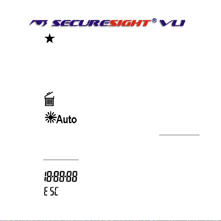
3. Definition of Control display.

© Securesight 2007 E&OE 9
•: Still image capture icon. Indicates your VL1 will
capture a single image.
•: 2 Photos burst capture icon. Indicates your VL1
will capture two consecutive images.
•: Image counter to show how many images or
videos have been captured.
•: Storage status icon. Only present if an external SD
card installed. If no icon your VL1 will use its internal built
memory.
•: Video-capturing icon. Indicates your VL1 is in video
capturing mode and will capture 10 second video bursts.
•: High-resolution icon. Indicates the VL1 is in high-
resolution still image capturing mode.
© Securesight 2007 E&OE 10
•: Low-resolution icon. Indicates the VL1 is in low-
resolution still image capturing mode.
•D: Date setting mode. Indicates when your VL1 is in Date
setting mode.
•T: Time setting mode. Indicates when your VL1 is in Time
setting mode.
•: Rubbish bin icon, Indicates the VL1 is in delete mode.
•: Floodlight control icon,
When showing, the floodlight will turn on if the camera sensor
detects the light levels are too low.
When the Icon is not showing the floodlight is turned on when
the photo sensor detects the light level has dropped below the
threshold set with the LUX control.
•: Shows the Date and time.
•: Pressing the SET button will exit the current mode.

© Securesight 2007 E&OE 11
4. Picture / Image Capacity
SD card High 2.0M
1600x1200 Low 1.3M
1280x1024 AVI QVGA
320x240
Built In
memory 8 12 2
16MB 26 40 8
32MB 52 80 16
64MB 104 160 32
128MB 208 320 64
256MB 416 640 128
512MB 832 1280 256
1GB 1664 2560 512

© Securesight 2007 E&OE 12
NOTE: Picture / Image Capacity Chart shows the approximate
number of images or video clips that can be stored based on the
resolution setting and the size of memory card. These figures
may vary depending on the amount of detail in the image. Also,
when your memory card is full, your VL1 will begin overwriting the
earliest data ensuring you always have the most recent images.
Memory Options – Up to 1Gb SD card
Your VL1 lighting camera is equipped with 16MB built in SDRAM
memory. Please note:- data stored on internal memory may be
lost in the event of a power failure. We therefore recommend the
use of external memory using the media card slot capable of
accepting up to 1GB SD card (sold separately). With no memory
card inserted into the slot, the camera will use the built in 16MB
SDRAM memory. If a SD card is inserted into the slot then the
camera will bypass the built in memory and write to the SD
memory. It is not recommended that a card is inserted or removed
during operation as this can cause malfunction. The counter
display will show the number of images on the built in memory and
will change to show the number on a memory card if one is fitted.
© Securesight 2007 E&OE 13
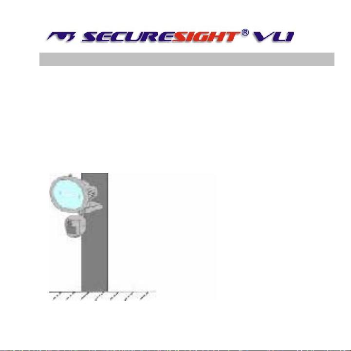
D. Mounting the camera
Mount the VL1 to a solid surface more than ½” thick in a secure
location overseeing the area to monitor. We suggest you mount
the camera between 2 and 4 meters off the ground with the
camera pointing at a downward angle. Be sure to avoid mounting
the camera facing east or west as the rising and setting of the
sun may produce false triggers and overexposed images.
Ensure the front of your VL1 is clear of any branches and other
debris so your camera view or PIR sensor are not obscured.
© Securesight 2007 E&OE 14
E. Camera setup – getting started
1. Inserting SD card
SD cards must not contain any other images and you
must ensure your VL1 is disconnected to AC power
when adding or removing an SD memory card. Failure
to observe these rules may result in malfunction.
•Your VL1 is supplied with a 512Mb SD card. Insert the SD
memory card in to the SD card slot completely and in the
correct direction as shown on the inside of the housing.
•DO NOT FORCE THE SD CARD
•To remove the SD memory card, push the SD card in and it
will spring out, now pull out the card gently.
2. Connect the VL1 to AC power. (See section L)
Please make sure your VL1 is rated for
your voltage before connection. Incorrect
voltage will damage the camera. This
product is intended for 220-240 VAC.

© Securesight 2007 E&OE 15

© Securesight 2007 E&OE 16
•Ensure you connect your VL1 in accordance with the wiring
diagram. Failure to do so may result in damage to your VL1
and will void your warranty.
•We recommend using a supply that you can switch off if
required. Once wired correctly, turn on the mains supply.
•When connected the VL1 lamp will turn on for
approximately 60 seconds whilst self-testing. It is then
ready for operation and will begin recording images each
time the motion sensor is triggered.
Replacing the halogen lamp if faulty
CAUTION your lamp will be very hot.
•Always disconnect the power to your VL1 before opening.
•Release the floodlight screw to open the floodlight cover.
•Carefully remove the Halogen lamp – it may be HOT.
•Insert a new Halogen lamp making sure you do not touch
the lamp with bare skin. Halogen Lamp : Max 500W R7S
•Close the floodlight cover and screw together carefully.

© Securesight 2007 E&OE 17
2. Settings.
You can change the settings on your VL1. The parameters that can
be changed and the default values are shown below. Please note
after changing any settings the test LED will flash and the unit will
count down for approx. 60 seconds before arming.
Setting Default
Time 00:00 HH:MM
Date 04:01:06 MM:DD:YY
Flicker frequency 50 Hz 50 / 60
Image capture interval 1 minute 0-60
Resolution High High/Low
Image capture method Video Video/Photo
Floodlight control Off On/Off
Your VL1 can be used straight away but before use you may wish
to change some or all of the settings – see the next sections.

© Securesight 2007 E&OE 18
3. Set the Data and Time.
•After mounting your VL1 (with SD card already fitted if
required) connect the camera to theAC power. The
camera will turn on automatically and will begin to count
down ready to arm.
•Press the SET and MODE button together once to enter
TEST MODE, the LCD will display the word
“t E S t ”.
•Press the MODE button
repeatedly untill the LCD
displays: “ T, 00-00 “ and
are flashing.
•Press the SET button
repeatedly to set the HOURS
•Press the MODE button to confirm.
•Now press the SET button repeatedly to set the MINUTES,
then press the MODE button to confirm.

© Securesight 2007 E&OE 19
•The display will now change to “4.01.06” representing the
date in the format MM.DD.YY
•Press the SET button to set the MONTH followed by the
MODE button to confirm.
•Repeat this process to set the Day and Year.
•Still images will be stamped with the time and date you set
here.
NOTE: Settings and images stored on internal memory
may be lost in the event of a power failure. Always
ensure you reset your VL1 following a loss of power.
4. Setting the flicker frequency 60Hz or 50Hz
By adjusting your VL1 to reflect the AC power frequency you
will eliminate any flicker effect on captured images.
For the UK this must be set to 50Hz.
•When VL1 is in TEST MODE, press the MODE button
repeatedly until the LCD flashes “ 60HZ ”

© Securesight 2007 E&OE 20
•Now press MODE button to change to 50Hz (UK)
•Press the SET button to confirm your choice. The LCD will
display “ dONE “ and then display “ ESC “
•Press the SET button again to exit and return to TEST
MODE.
•Press the MODE and SET button together again to leave
the TEST MODE.
5. Testing the sensor coverage area
In test mode the VL1 allows you to test the coverage area.
•After mounting connect your camera to AC power, the
camera will turn on automatically.
•It will now start to count down to arm – approx 60 seconds.
Other manuals for VL1
1
Table of contents


