Secutron MR-2602 User manual

INSTALLATION
MANUAL
Revision: 2 022708
Document #: LT-2015
WARNING: This manual contains information on limitations
regarding product use and function and information on the
limitations as to liability of the manufacturer. The entire
manual should be read carefully.
MR-2602
Fire Alarm Control Unit


MR-2602 Installation & Operator’s Manual
i
Table of Contents
1.0 Introduction .............................................................................................................................................. 1
1.1 The MR-2602 Fire Alarm Control Unit ............................................................................................ 1
1.2 Codes, Standards and Installation Requirements........................................................................... 1
1.3 Technical Support and General Information ................................................................................... 2
1.4 System Verification ......................................................................................................................... 2
1.5 Standby Power................................................................................................................................ 2
1.6 Battery Maintenance ....................................................................................................................... 2
2.0 Preparing to Install the MR-2602 Fire Panel ............................................................................................ 3
2.1 Unpacking the MR-2602 ................................................................................................................. 3
2.2 Optional Accessories ...................................................................................................................... 3
2.3 MR-2602 Overview ........................................................................................................................ 4
2.4 Planning Your Installation ............................................................................................................... 5
2.5 Electrical Specifications .................................................................................................................. 5
2.6 Module Current Ratings .................................................................................................................. 6
2.7 Standby Battery calculation chart ................................................................................................... 6
2.8 Calculation for Standby Battery Requirement................................................................................. 7
3.0 Installing the MR-2602 Fire Panel............................................................................................................ 8
3.1 Environmental Specifications.......................................................................................................... 8
3.2 Panel Assembly and Modules Locations ........................................................................................ 8
3.3 Mounting the MR-2602 ................................................................................................................... 9
4.0 Wiring the MR-2602 ................................................................................................................................. 10
4.1 Wiring Specifications....................................................................................................................... 10
4.2 Connecting NAC Devices (Class ‘A’ and Class ‘B’) ........................................................................ 12
5.0 Panel Operation ....................................................................................................................................... 16
5.1 Operating Sequences ..................................................................................................................... 16
5.2 General Zone Fire Alarms............................................................................................................... 16
5.3 Waterflow Alarms............................................................................................................................ 16
5.4 Supervisory Zone Alarms................................................................................................................ 17
5.5 Trouble Operation ........................................................................................................................... 17
5.6 System Reset Operation................................................................................................................. 19
5.7 Lamp Test ....................................................................................................................................... 19
5.8 Walk Test (Installer function only)................................................................................................... 20
5.9 NAC operation ................................................................................................................................ 21
5.10 Relay Function .............................................................................................................................. 21
6.0 Programming the MR-2602 System......................................................................................................... 22
6.1 How to Program the MR-2602 ........................................................................................................ 22
6.2 Programming Section Descriptions................................................................................................. 24
6.3 Viewing the Event Buffer................................................................................................................. 27
7.0 Startup of the MR-2602............................................................................................................................ 29
7.1 Prior to power up............................................................................................................................. 29
7.2 Power up sequence ........................................................................................................................ 29
7.3 Default Operation............................................................................................................................ 29
7.4 Programming the Panel .................................................................................................................. 29
7.5 Final Verification ............................................................................................................................. 29
8.0 Programming Worksheets ....................................................................................................................... 30
8.1 Entering Programming Mode .......................................................................................................... 30
8.2 Zone Programming (Section 0)....................................................................................................... 31
8.3 NAC Temporal/Steady Programming (Section 1) ........................................................................... 31
8.4 NAC Auto-silence, Strobe Programming (Section 2) ...................................................................... 31
8.5 Silence Inhibit and Walk Test Programming (Section 3)................................................................. 32
8.6 Waterflow Programming (Section 4) ............................................................................................... 32
8.7 50/60 Hz Option (Section 5)............................................................................................................ 32

MR-2602 Installation & Operator’s Manual
ii
9.0 Appendix: Table of Compatible Smoke Detectors ................................................................................... 33
9.1 Smoke Detector Bases ................................................................................................................... 35
9.2 Compatible 4-Wire Smoke Detectors.............................................................................................. 35
9.3 Compatible Horns/Strobes.............................................................................................................. 36
FCC Compliance Statement .......................................................................................................................... 38
Warranty & Warning Information.................................................................................................................... 39

MR-2602 Installation & Operator’s Manual
iii
List of Figures
Figure 1: MR-2602 cabinet with door closed ....................................................................... 4
Figure 2: MR-2602 display and controls ............................................................................. 4
Figure 3: MR-2602 Cabinet Overview ................................................................................. 4
Figure 4: Zone Label Insert ................................................................................................. 4
Figure 5: Panel Assembly and Modules Locations ............................................................. 8
Figure 6: Mounting Dimensions .......................................................................................... 9
Figure 7: Knockout Locations .............................................................................................. 9
Figure 8: MR-2602 Terminal Descriptions ......................................................................... 10
Figure 9: Connecting 2-Wire Alarm Initiating Devices ......................................................... 11
Figure 10: Connecting 4-Wire Smoke Detectors ................................................................. 12
Figure 11: Connecting NAC Devices (Class ‘B’) ................................................................. 12
Figure 12: Connecting NAC Devices (Class ‘A’) ................................................................. 12
Figure 13: Connecting Batteries .......................................................................................... 13
Figure 14: Connecting AC Power ........................................................................................ 13
Figure 15: Connecting the Alarm and Trouble Relays ........................................................ 14
Figure 16: Connecting Optional Devices ............................................................................. 14
Figure 17: Locating the Walk Test Switch ........................................................................... 22


MR-2602 Installation & Operator’s Manual
1
1.0 Introduction
1.1 The MR-2602 Fire Alarm Control Unit
General features
•Two initiating device circuits, class B / style B
•Two notification appliance circuits, class B / style Y (Power Limited)
[can be wired as one NAC, class A / style Z]
•One common alarm-actuated relay, form ‘C’
•One common trouble-actuated relay, form ‘C’
•AUX+ power output, 500 mA max. (Power Limited)
•Unswitched common and switched common auxiliary power returns
•Integral battery charger
•Cabinet with dead-front construction
•Transformer, mounted in the cabinet
Applications
The MR-2602 two zone, fire alarm control panel is listed for use in the following applications.
•Protected Premises Fire Alarm System
•And for the following types of service:
A – automatic, M – Manual, SS – Sprinkler Supervisory, WF – Waterflow
1.2 Codes, Standards and Installation Requirements
Relevant codes and standards
The MR-2602 fire alarm control panel is designed to meet the requirements of NFPA 72, 2002 edition, UL 864
Rev 9, Control Units for Fire Protective Systems, and in Canada, CAN/ULC-S527-99, Standard for Control
Units for Fire Alarm Systems.
Information provided with this unit is intended as a guide. Installation of this equipment, optional system
components, alarm initiating devices and notification appliances must follow the manufacturer’s guidelines as
contained in their respective installation documents, all applicable codes and the instructions of the Local
Authority Having Jurisdiction.
General Installation requirements
Manufacturer’s documents
When installing the MR-2602 control panel, refer to this manual. When installing optional system components
refer to the installation documents included with those components. When installing compatible alarm initiating
devices or notification appliances, refer to the installation documents included with those products.
Field wiring
Field wiring recommendations in this document are intended as guidelines. All field wiring must be installed in
accordance with NFPA 70 National Electrical Code and in Canada with the standard for installation ULC/S
524, the most current Canadian Electrical Code, with all relevant local codes and standards, and the Authority
Having Jurisdiction.
Compatible devices
Use UL or ULC Listed smoke detectors and notification appliances that are compatible with the MR-2602 Fire
alarm control panel from the lists included in this manual.

MR-2602 Installation & Operator’s Manual
2
1.3 Technical Support and General Information
For technical support call 1-888-SECUTRON, or email techsupport@secutron.com
For general product information visit the Secutron web site: www.secutron.com.
1.4 System Verification
The complete fire alarm system must be verified for proper installation and operation when:
•the initial installation is ready for inspection by the Local Authority Having Jurisdiction;
•any system component is added, changed or deleted;
•any programming changes are made;
•system wiring has been altered or repaired;
•system failure due to external influences such as lightning, water damage or extended power outages has
occurred.
1.5 Standby Power
The MR-2602 provides standby battery support for lead-acid rechargeable batteries. The required capacity of
the standby batteries must be calculated using the charts and tables within this manual for the period as
required by national or local codes and standards. Even though the calculation table within this manual
includes a safety margin, lead-acid batteries commonly used for standby can have variable capacity as a
result of age and ambient conditions. Periodic inspection for damage and the batteries’ ability to support the
attached equipment is highly recommended.
1.6 Battery Maintenance
The two 12V sealed lead-acid batteries should be replaced after each period of 3 to 5 years of normal service.
If the Battery Trouble indicator activates, obtain required service.

MR-2602 Installation & Operator’s Manual
3
2.0 Preparing to Install the MR-2602 Fire Panel
2.1 Unpacking the MR-2602
The basic MR-2602 package includes the following components:
•Cabinet with hinged door
•Display and control plate c/w display and control printed circuit board.
•Zone label insert
•Battery compartment dead front plate
•Main control PCB
•Transformer
•Installation manual
•Hardware pack
-- 2 × NAC EOL resistors (4.7 K, 5%, ½ W)
-- 2× Zone EOL resistors (4.7 K, 5%, ½ W)
-- 1 × Battery jumper wire
-- 1 × EGND terminal ring
-- 1 × EGND KEP nut
• Door keys (taped to outside of cabinet)
All components described above are factory assembled into the enclosure.
2.2 Optional Accessories
Model Number Name Description
MR-2605-R3 Relay module
Provides 3 relays that are jumper programmable to activate on
common ‘alarm’, ‘supervisory’ or ‘trouble’. Mounts inside the enclosure
and plugs into the main board.
MR-2806 Dual line dialer
Communicates all alarms, supervisory and trouble conditions to a
Central Station using Contact ID, SIA or 10/20 BPS communication
formats. Programmable using the MR-2644 handheld programmer.
Mounts inside the enclosure and connects to the main panel using a
supplied 4-wire cable with connector.
MR-2644 Programmer Handheld programmer for the MR-2806 DACT.
MR-2605-T Remote trouble
indicator
Single gang plate complete with common trouble buzzer, trouble
visual indicator, ‘AC on’ visual indicator and a trouble silence / lamp
test switch. Mounts remotely to a single gang electrical box and is
connected to the main panel via the 4-wire ‘secur-bus’.
MR-2605-AT
Remote trouble
indicator and alarm
indicator
Two gang plate complete with common trouble buzzer, trouble visual
indicator, ‘AC on’ visual indicator and a trouble silence / lamp test
switch and red zone alarm visual indicators and yellow zone
supervisory indictors. Mounts to a standard 2 gang electrical box and
is connected to the panel via the 4-wire ‘secur-bus’.
MR-2605-SR EOL supervision
relay
Supervises the extended power wiring typically used for installations
that employ 4-wire smoke detectors. Mounts in the field.
MRD-EOL4.7K EOLR End-of-Line resistor for NAC and Initiating circuits. Mounts in the field.
MRD-MP400 EOLR plate Single gang plate with EOL resistor. Mounts to a single gang electrical
backbox.
MR-2602 Installation & Operator’s Manual
4
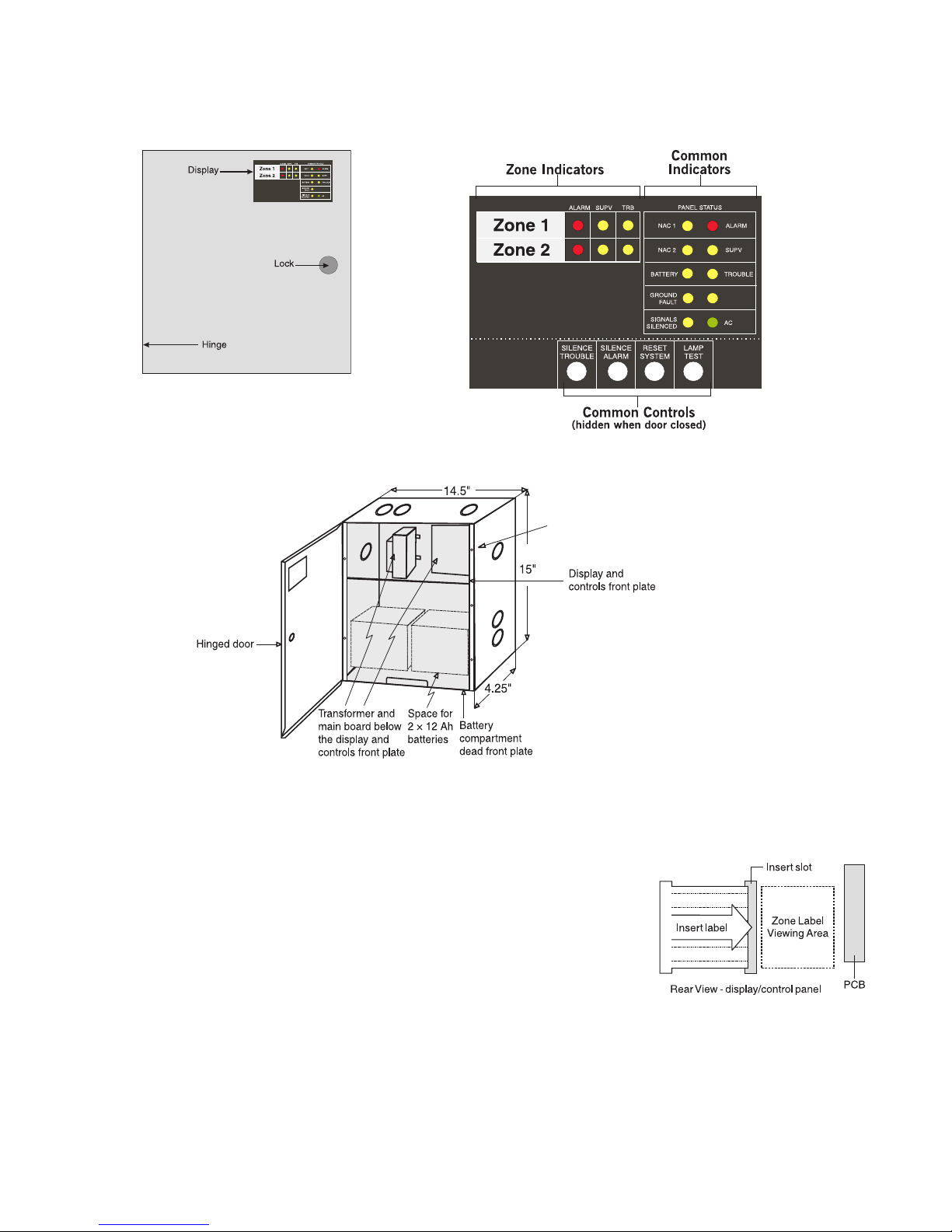
2.3 MR-2602 Overview
Zone Label Insert
A zone label insert is installed in the zone window area. Reach behind
the display/control panel and remove the blank insert. Zone designations
can be written directly on the insert or can be created using Word for
Windows, printed on Avery label #5167 and applied to the insert.
CPU
FAULT
Figure 1: MR-2602
cabinet with door closed
Note: Use Security Screw(SPAENAUR #381-064)
provided to meet UL 864 Rev 9 requirement
Figure 2: MR-2602 display and controls
Figure 3: MR-2602 Cabinet Overview
Figure 4: Zone Label
Insert
MR-2602 Installation & Operator’s Manual
5
2.4 Planning Your Installation
As a minimum, the following points should be considered to ensure that the installation will be successful and
proceed without delay.
•Consult with your local AHJ to ensure that the overall system will meet all requirements. Have your plans
reviewed and approved as required.
•Review the electrical specifications, mounting and wiring instructions in this manual and in the manuals of
all connected modules and devices.
•Using the chart in this manual, calculate the standby battery size that will meet the standby time required.
Include all components that will draw current from the standby battery when the panel is in the ‘standby’
mode.
•Determine the location of the control panel, all initiating and indicating devices and remote modules and
mark them on your system layout plan. An indicating device must be located in close proximity to the control
panel.
•Using the charts in this manual, determine the wire gauge and wire run distances for the connected
components. (initiating devices, indicating devices and ‘secur-bus’ connected components.)
•Review the programming section of this manual and determine the operating characteristics required of the
initiating zones, indicating zones and common panel features.
2.5 Electrical Specifications
Note: This system should be installed and serviced by qualified fire alarm installation professionals.
Circuit Rating
Primary AC 120 volts, 60 Hz. 1.5 Amps maximum/240 volts, 50 Hz. 1.0 Amps
maximum
AUX+ 500 mA maximum ~ Restoral of Aux Power Shorts requires removal of
all Aux Power loading
SCOM 500 mA maximum (current sink)
COM 500 mA maximum (current sink)
Relays (common alarm &
trouble) Form ‘C’ contact, 2 Amp, 30 VDC resistive, power limited source
NAC Outputs 24 volts, full-wave rectified DC, 1.5 Amps max. – Power limited. (3.0
Amps total for both NAC circuits) EOLR – 4.7K ohm, ½ W, 5%
Initiating Zone Inputs 24 VDC, 60 mA max.(in alarm) – Supervisory current: 6.0 mA – max.
Loop resistance: 100 ohms max. – EOLR: 4.7 K ohm, ½ W, 5%
Battery Charging Current 270mA maximum
Low Battery Trouble
Low Battery Trouble: 22.0 VDC
Low Battery Trouble Restore: 23.0 VDC
Critical Shutdown: 19±0.5 VDC
MR-2602 Installation & Operator’s Manual
6
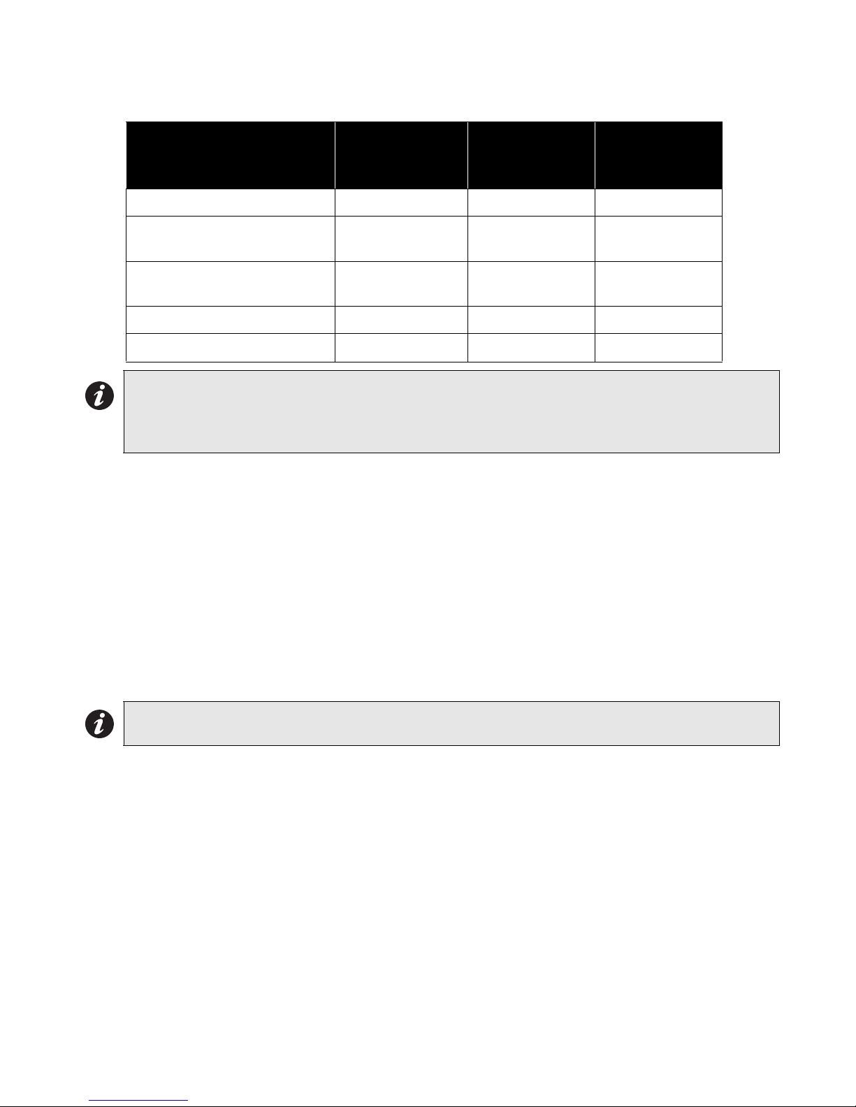
2.6 Module Current Ratings
2.7 Standby Battery calculation chart
All components that draw current from the panel while it is in the ‘standby’ mode (AC OFF) must be
considered for the standby battery calculation. All components that draw current while in the ‘Alarm’ mode
must be considered for the alarm battery calculation.
1. The control panel will always draw the currents as shown in the chart.
2. Typically the alarm current is calculated assuming only one initiating zone is in alarm. If it is required that
more than one zone be considered, add 60 mA per zone in the Alarm column. Consult the smoke detector
manufacture’s installation sheet to determine the standby current of these devices. Write that number in
the ‘current per device’ column then multiply that number by the number of devices on the zone. Repeat for
each zone.
3. Consult the Notification Appliance installation sheet to determine the current draw for each device
connected to the NAC. For each NAC, calculate the total current in alarm and put that number (mA) in the
‘Alarm’ column.
4. For each added module in the system, multiply the number of modules times the module ‘standby’ and
‘alarm’ currents and write those totals in the ‘standby’ and ‘alarm’ columns.
5. Add up all the current drawn from the AUX+ output in the standby and alarm mode and put those totals in
the ‘standby’ and ‘alarm’ columns.
6. Add up all the currents in the ‘standby’ column and the ‘Alarm’ column.
7. Convert the ‘standby’ and ‘alarm’ currents from mA to Amps. (divide mA by 1000)
8. Write in the ‘standby’ time required. (24 or 60 Hr.)
9. Multiply the ‘standby’ Amps times the ‘standby’ time to get the ‘standby’ Amp-Hr. required.
10.Write in the ‘alarm’ time required in hours. (5 min. =.08 Hr.; 30 min. =0.5 Hr.)
11. Multiply the ‘alarm’ Amps times the ‘alarm’ time to get the ‘alarm’ Amp-Hr required.
12.Add the ‘standby’ Amp-Hr. to the ‘alarm’ Amp-Hr. for the total Amp-Hr. required.
13.Multiply the total Amp-Hr. times 1.20 for the minimum Amp-Hr. battery required to support the system for
the selected ‘standby time and the selected ‘alarm’ time.
Module Standby Current
(mA) DC
Alarm Current
(mA) DC
Max. Alarm
Current (mA)
DC
MR-2602 Control panel 90 425(*) 485
MR-2605-T Remote trouble
indicator 15 15 15
MR-2605-AT R.T.I. and remote
5 zone annunciator 15 20(*) 40
MR-2806 DACT 45 60 60
MR-2605-R3 Relay module(**) 0 24 24
Note: *Current noted assumes ONE initiating zone is in alarm. The “Max. Alarm Current” assumes all
zones are in alarm.
**Values shown are for all relays set for activation on ‘Alarm’. Each relay set for activation on
‘trouble’ is normally energized and on ‘AC fail’ will draw 0 mA.
Note: Each NAC can supply 1.5 Amps max.
MR-2602 Installation & Operator’s Manual
7
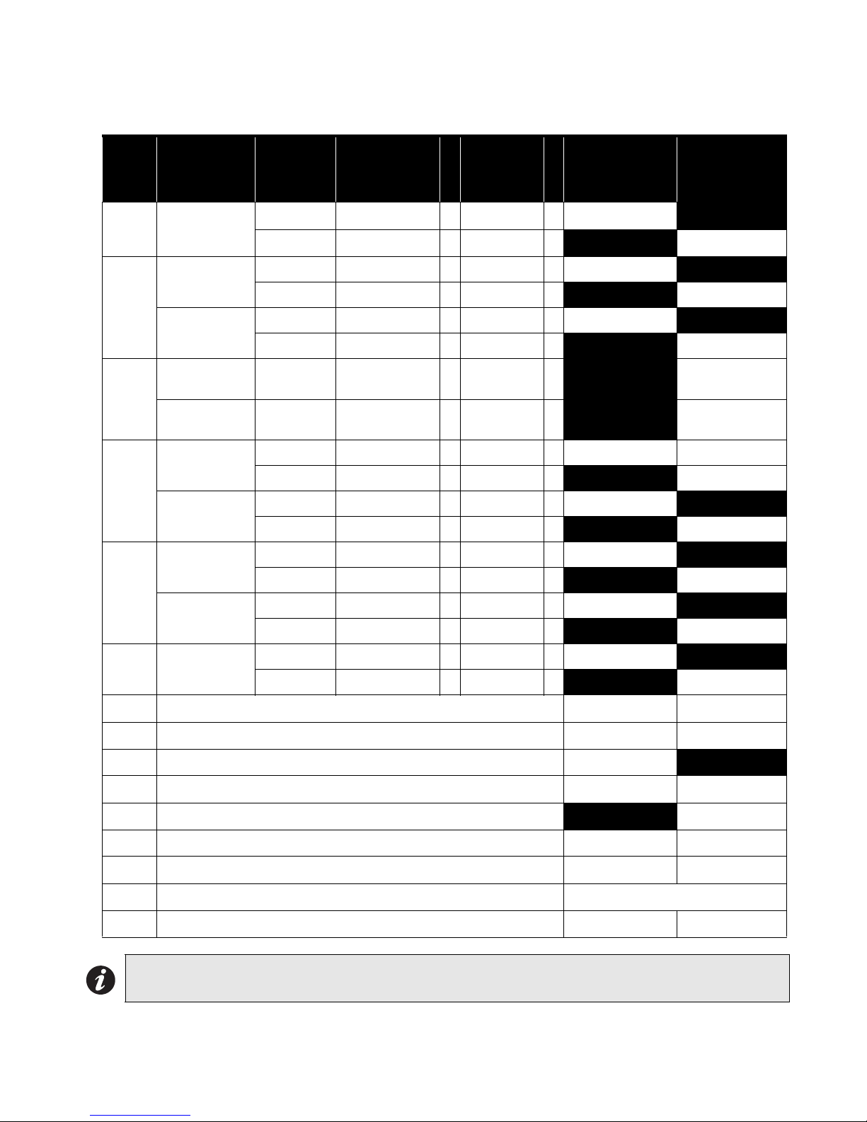
2.8 Calculation for Standby Battery Requirement
Step Device Current per
device (mA)
Number
of device
Total
Standby
Current (mA)
Total Alarm
Current
(mA)
1 MR-2602
Standby: 90 x1 =90
Alarm: 365 x1 = 365
2
Zone 1
Standby: x =
Alarm: 69 x 1 = 69
Zone 2
Standby: x =
Alarm: 69 x 1 =
3
NAC 1 Alarm: x =
NAC 2 Alarm: x =
4
MR-2605-T
Standby: 15 x
Alarm: 15 x
MR-2605-AT
Standby: 15 x
Alarm: 25 x
MR-2806
Standby: 45 x
Alarm: 60 x
MR-2605-R3
Standby: 0 x =
Alarm: 24 x
5AUX+
Standby: x =
Alarm: x =
6Total ‘standby’ and ‘alarm’ current: mA mA
7Divide ‘standby’ mA and ‘alarm’ mA by 1000: Amp Amp
8Select ‘standby’ time required (24 or 60 Hr.): Hr.
9Standby Amp-Hr. - multiply 8 × 7 = (Amps × Hr.): Amp-Hr.
10 Select ‘alarm’ time required (0.08 or 0.5):Hr.
11 Alarm Amp-Hr. - multiply 7 × 10 = (Amps × Hr.): Amp-Hr.
12 Total Amp-Hr = standby Amp-Hr (9) + alarm Amp-Hr. (11): Amp-Hr.
13 Multiply the total Amp-Hr. by the safety margin: 1.20
14 Total battery Amp-Hr required to support the system: Amp-Hr.
Note: Select a battery with an Amp-Hr. rating that is equal to or larger than the calculated minimum Amp-
Hr. battery required.
MR-2602 Installation & Operator’s Manual
8
3.0 Installing the MR-2602 Fire Panel
3.1 Environmental Specifications
Consider the following conditions when selecting a mounting location for the MR-2602 panel:
•Operating temperature: 32°F to 122°F / 0°C to 50°C
•Humidity: 95% RH non-condensing
•Close to a source of unswitched AC power
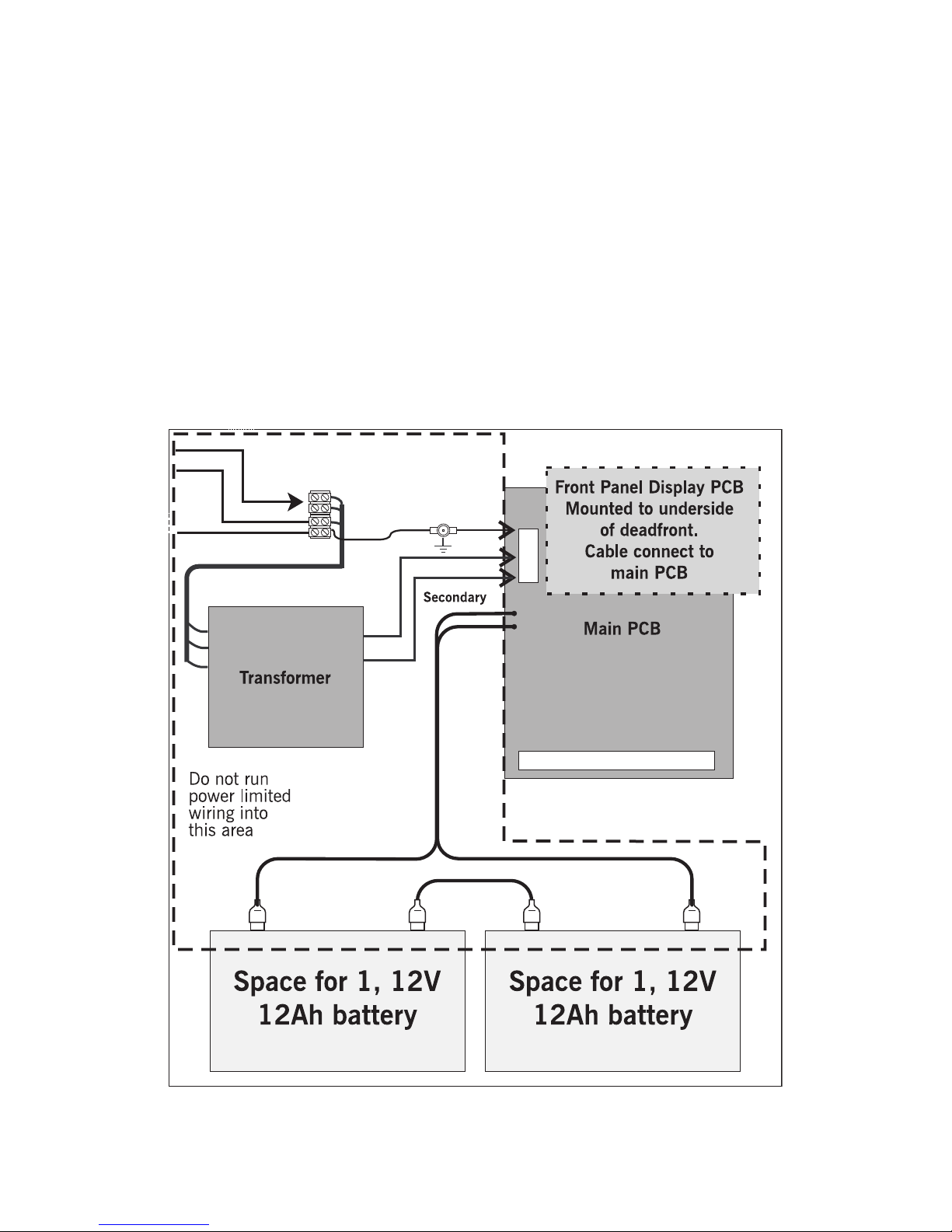
3.2 Panel Assembly and Modules Locations
The panel comes completely assembled from the factory. Remove the lower dead front for access to the
battery compartment. Remove display control panel for access to AC connections.
Figure 5: Panel Assembly and Modules Locations
240V 50Hz
120V 60Hz
GND
N
Primary AC
MR-2602 Installation & Operator’s Manual
9
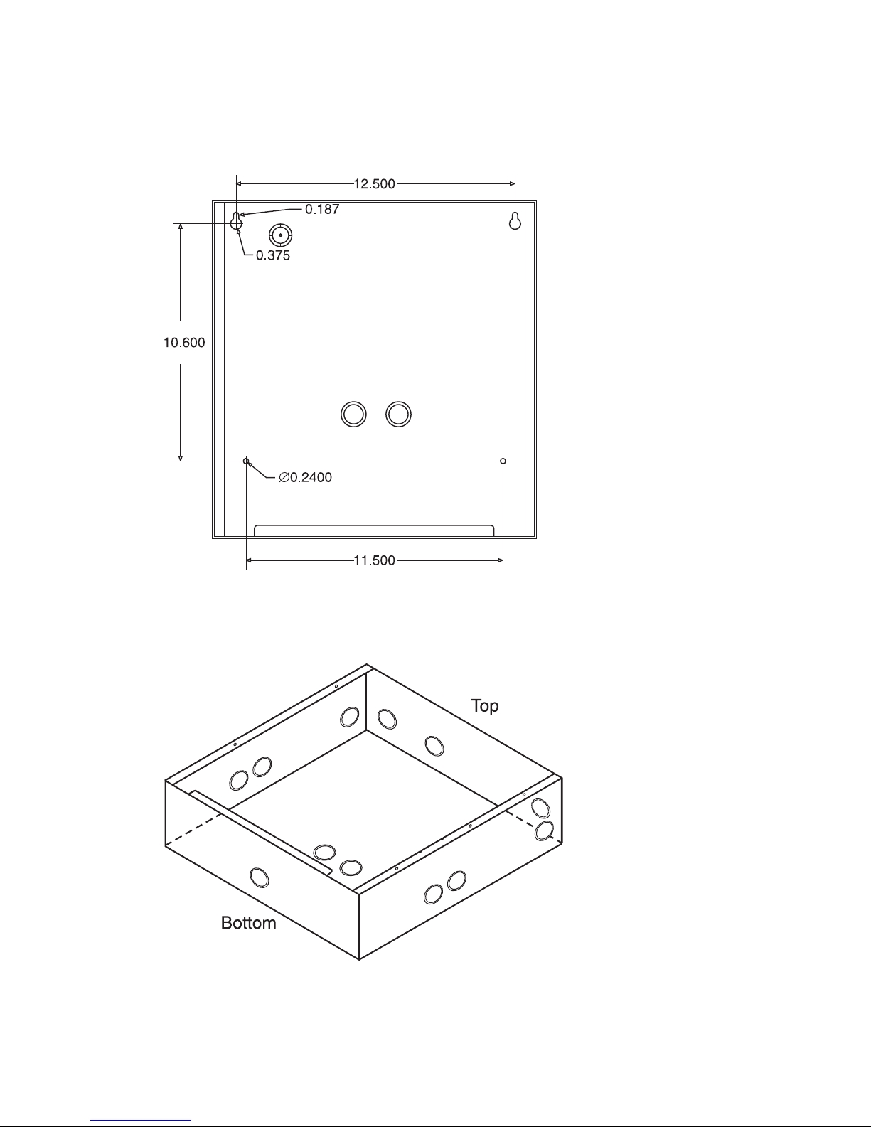
3.3 Mounting the MR-2602
Figure 6: Mounting Dimensions
Figure 7: Knockout Locations
Dimensions in inches

MR-2602 Installation & Operator’s Manual
10
4.0 Wiring the MR-2602
4.1 Wiring Specifications
Figure 8: MR-2602 Terminal Descriptions
Terminal
Label Description
NAC 1
(+, –)
Notification Appliance Circuit # 1
24 VDC, Full-Wave Rectified voltage, 1.5 Amps max.
Programmable as Steady or Temporal output on alarm.
Supervised for opens, shorts and ground fault.
Power limited.
NAC 2
(+, –)
Notification Appliance Circuit # 2
24 VDC, Full-Wave Rectified voltage, 1.5 Amps max.
Programmable as Steady or Temporal output on alarm.
Supervised for opens, shorts and ground fault.
Power limited
AUX+
Auxiliary power output
24 VDC, filtered and regulated, 500 mA max., 400 mV P-P ripple, power limited. Aux
power shorts must be restored by removing all Aux Power loading.
COM Auxiliary common power return, unswitched
24 VDC, 500 mA max.
SCOM
Auxiliary common power return, switched
(open circuit on system reset or on 4-wire smoke detector reset)
24 VDC, 500 mA max. (Please refer to Appendix A for compatible 4-wire smoke
detectors.)
DAT Data line for remote module communications
CLK Clock line for remote module communications
TRB NO Common Trouble relay, Normally Open contact
TRB C Common Trouble relay, Common contact
TRB NC
Common Trouble relay, Normally Closed contact
The Common Trouble relay is normally energized and is de-energized on trouble.
Contacts are shown in the de-energized state.
Contacts are rated 30 VDC, 2 Amps.
ALM NO Common Alarm relay, Normally Open contact
ALM C Common Alarm relay, Common contact

MR-2602 Installation & Operator’s Manual
11
Figure 9: Connecting 2-Wire Alarm Initiating Devices
Typical
1. Maximum 30 smoke detectors per zone (100 µA each standby).
2. Manual station, heat detector.
3. Maximum total loop wire resistance = 100 ohms.
4. Program zone as:
Type 1 - Smoke and contact devices instant alarm (default)
Type 2 - Smoke auto-verify and contact as instant.
ALM NC
Common Alarm relay, Normally Closed contact
The Common Alarm relay is normally de-energized.
Contact is shown in the de-energized state.
Contacts are rated 30 VDC, 2 Amps max.
Z1+ Zone 1 positive input
Z1-
Zone 1 negative input
Zone output is 24 VDC nominal to power 2-wire smoke detectors. Maximum current
draw is 60 mA in alarm and is limited by the zone circuitry. Zones may be configured to
monitor both 2-wire smoke detectors and initiating devices that employ dry contacts.
(manual stations & heat detectors)
Z2+ Same as zone 1 positive
Z2-Same as zone 1 negative
Note: For each supervised installation wire, a separate terminal must be used.
* See “9.0 Appendix: Table of Compatible Smoke Detectors” on page 33 in this manual for a list of
compatible 2-wire smoke detectors
Terminal
Label Description
MR-2602 Installation & Operator’s Manual
12
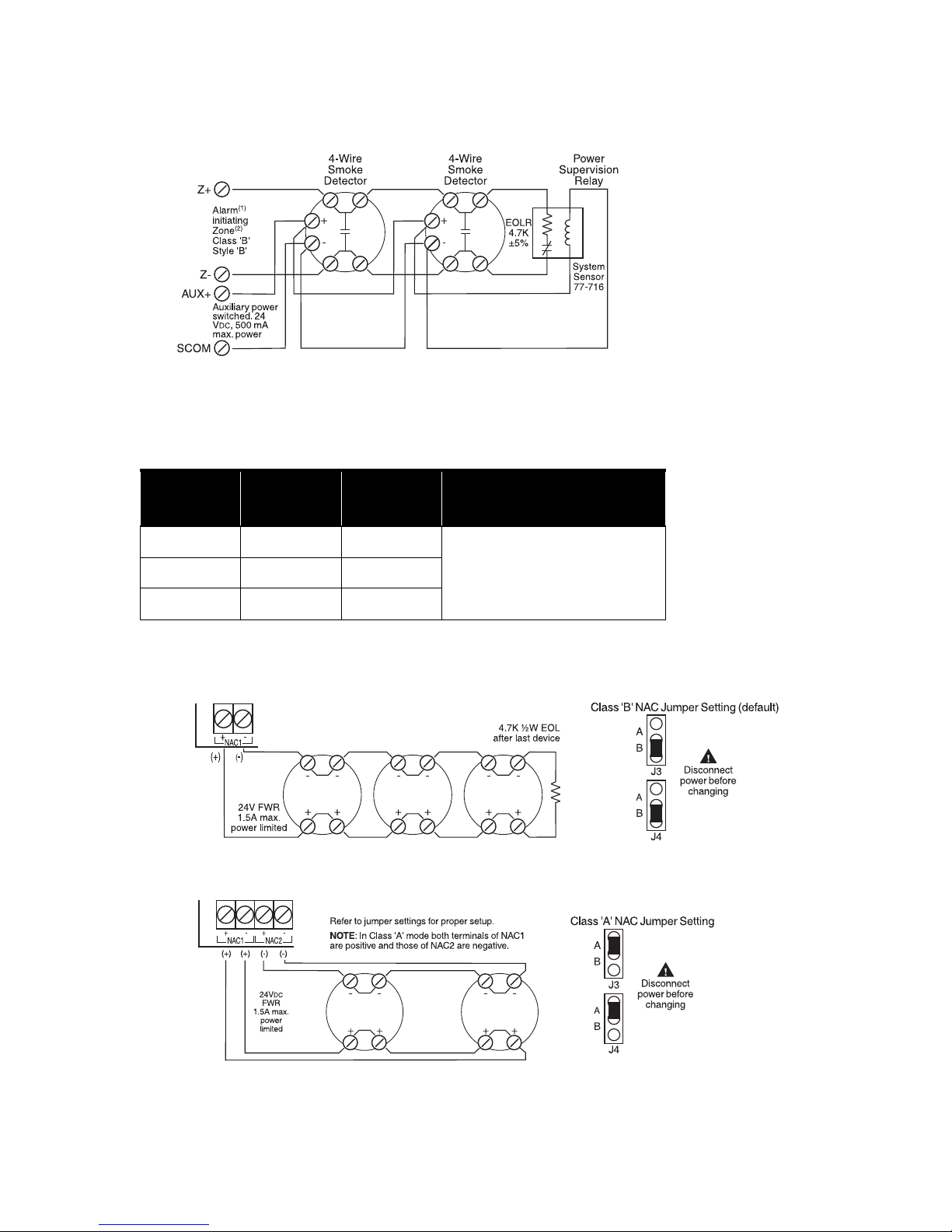
Figure 10: Connecting 4-Wire Smoke Detectors
1. Program as zone type 01, instant alarm.
2. Maximum total loop wire resistance is 100 ohms.
Zone Wiring Chart:
4.2 Connecting NAC Devices (Class ‘A’ and Class ‘B’)
Figure 11: Connecting NAC Devices (Class ‘B’)
Figure 12: Connecting NAC Devices (Class ‘A’)
Wire
(Gauge)
Distance
(feet)
Distance
(meters)
18 7,690 2,345 Maximum loop resistance is
100 ohms. Maximum current
in alarm is 60 mA.
16 12,195 3,717
14 19,230 5,861

MR-2602 Installation & Operator’s Manual
13
NAC Wiring Chart
Figure 13: Connecting Batteries
Figure 14: Connecting AC Power
Maximu
m Total
Loop
(ohms)
Maximu
m
Current
(A)
18-Awg
Wire
16-Awg
Wire
14-Awg
Wire
12-Awg
Wire
ft mft mft mft m
8.00 0.25 615 188 978 297 1,538 469 2,500 762
5.00 0.50 308 94 488 149 769 235 1,250 381
2.70 0.75 205 63 325 99 513 156 833 254
2.00 1.00 154 47 244 74 385 117 625 191
1.60 1.25 123 38 195 59 308 94 500 152
1.30 1.50 103 31 163 50 256 78 417 127
Note: This chart is based on a minimum source voltage of 22 volts and a maximum line loss
of 2 volts thus leaving a minimum of 20 volts at the last notification appliance.
240V 50Hz
120V 60Hz
GND
N
Primary AC
Note: The wire gauges must be
no less then the size required by
the Canadian Electrical Code
C22.1, Part 1, Section 32.

MR-2602 Installation & Operator’s Manual
14
Figure 15: Connecting the Alarm and Trouble Relays
Figure 16: Connecting Optional Devices
See installation sheets for the remote devices for
detailed wiring and address setup.
1. Maximum of 4 MR-2605-T per panel.
2. Maximum of 4 MR-2605-AT per panel.
Secur-bus Wiring Chart
Current
(mA)*
22-awg Wire 18-awg Wire 16-awg Wire 14-awg Wire
ft ft ft mft mft m
15 2,524 769 6,410 1,954 10,160 3,098 16,000 4,878
30 1,262 384 3,200 976 5,080 1,549 8,000 2,439
45 842 256 2,135 651 3,385 1,032 5,340 1,628
60 631 192 1,600 488 2,540 774 4,000 1,220
75 505 154 1,280 390 2,030 619 3,200 976
90 421 128 1,065 325 1,690 515 2,670 814
105 361 110 915 279 1,450 442 2,285 697
120 315 96 800 244 1,270 387 2,000 610
135 281 86 710 216 1,125 343 1,780 543
150 252 77 640 195 1,015 309 1,600 488
165 229 70 580 177 920 280 1,455 444
180 210 64 530 162 845 258 1,335 407
195 194 59 490 149 780 238 1,230 375
210 180 55 455 139 725 221 1,145 349
225 168 51 425 130 675 206 1,065 325
*See module current ratings chart for current drawn by each module attached to the secur-
bus.
Table of contents
Other Secutron Smoke Alarm manuals


