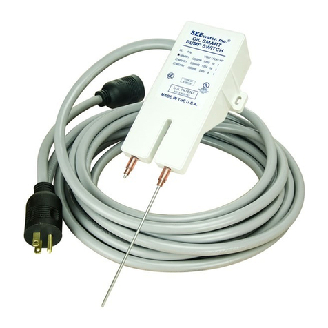
See Water Water Smart WSS12 Setup guide

Water Smart® SCS Switch (Model #WSS12 or WSS24)
Sing
#
www.seewaterinc.com
or www.oilsmart.org
951.487.8073 • 888.733.9283
Email: info@seewaterinc.com
121 North Dillon Street • San Jacinto, CA 92583
P.O. Box 1269 • San Jacinto, CA 92581
Fail-Safe Technology since 1995.
©Copyright 2009 See Water, Inc. All Rights Reserved.
Installation and Operator's Manual
Water Smart®Switch:
The Water Smart® SCS Bilge Pump Switch is
designed for use as an electronic bilge pump switch in
boats. An upgrade from the original “Water Smart
Switch”, the SCS now features microprocessor
memory for constant self-calibration to adapt to any
environment for reliability. Installation of the Water
Smart Switch allows you to comply with State and
Federal regulations while reducing the risk of adverse
publicity, fines and expensive cleanup costs from a
large Oil Spill.
Model Description Volts Amps
WSS12 Water Smart SCS Bilge Pump Switch 12VDC 12A
WSS24 Water Smart SCS Bilge Pump Switch 24VDC 12A
Features:
• No Moving Parts. Patent Pending Electronic Water
Smart® Pump Switch
• Outlasts any other bilge pump switch through Self
Calibrating Sensor (SCS) technology.
• After each cycle, the switch recalibrates to its
original settings compensating for any
environmental changes.
• Environmentally Responsive: Prevents major oil
spills. Oil will not activate the switch
• Small enough switch to not overcrowd the bilge
and can be placed at any predetermined level.
• Incorporates a pump on level sense point, an
eight (8-10) second time delay allowing for
maximum water elimination as well as the
elimination of pump cycling for prolonged pump
life. Includes backup sensor with its own pump
down time-delay for ultimate “pump on”
protection
• Solid state circuitry - no moving parts
• Defined trip point-Oil/fuel spills will not activate
pump
• Performance is not hampered by accumulated oil
and grease
• Extended sensors allow the switch to be mounted
high above the contaminated water
• UL 508 Marine Listed "Electrical Industrial
Control Equipment" and NFPA 302
• UL Listed in accordance with ISO 8846-
Protection against ignition of surrounding
flammable gases
Water Smart Bilge Installation:
I. Disconnect voltage source, route and secure
all wires as high as possible above the water
level.
II. Mount switch in the vertical only, do not
mount horizontally on bottom of bilge.
Complete Mounting Hardware included.
III. Be sure the bottom of switch sensor (turn on
level) is aligned high enough above the
pump impeller (1 to 4 inches) for proper
turn off and turn on.
IV. For maximum efficiency of the eight (8-10)
second delay the switch should be placed
high enough that when the switch detects
water, the switch turns on and runs for 8-10
seconds after it no longer detects water. At
this time the water would be eliminated at
the same time the pump turns off.
V. If the switch is installed too low,the proper
dead span (amount of distance between on
and off) will not be achieved, the pump will
continue to run pumping any oil/fuel that
might be floating on the surface of water.

Water Smart® SCS Switch (Model #WSS12 or WSS24)
Water Smart Switch Wiring:
I. Connect the switch positive (+) red wire to
the (+) source with a 12Amp maximum
fuse within 2’ of switch location, failure to
install fuse protection will void warranty
and may damage the boat.
II. Connect the switch and the negative (-)
black wire to the (-) negative source.
III. Connect the positive (+) brown wire from
switch to the positive (+) wire of pump and
pump manual wire if equipped, reconnect
voltage source.
IV. The switches shall be installed where the
water intrusion will not directly contact or
splash the white plastic case.
V. Mud or other conductive materials left on
the body of the switches will hamper its
operation; take effort to clean the switch
prior to initial installation.
VI. Mount with enclosed screws.
Note: Keep sensors at least 2” clear of any
metallic material.
Wiring Diagram:
Source DC
- + Water
Smart
Switch PUMP
Red
Black - Black -
Brown +
Red or Brown
+ Manual Switch
(If Equipped)
Testing:
• Place finger on stainless steel sensor of long sensor
and the pump will turn on. Remove finger from
sensor and the pump will remain on for an
additional 8-10 seconds. To test the backup sensor,
touch finger to short sensor and the pump will turn
on for 8-10 seconds after finger is removed.
Troubleshooting:
Problem Possible Cause and Solution
No Water
Pumped.
Pump Does
Not Run
Make sure wire connections are not
corroded. Visual check is not enough --
a slight pull of each wire will tell if the
wires are still joined. Ensure wires are
not in the water
Blown Fuse
Check fuse to see that it is the correct
size recommended by manufacturer. DO
NOT exceed amp rating. If fuse size is
correct and fuse still blows, check
impeller to be sure it is not jammed or
full of debris.
Pump Control
is not
operating
properly; not
consistent or
staying on
The switch may be mounted too low for
the pump and should be reinstalled
higher. Make sure the bottom of the
switch sensor is higher than the top of
the pump impeller/ intake. Make sure
the plastic switch case is clean of soap or
soap bi-products. Clean switch case with
alcohol or oil based product: cleaning
solvent, kerosene, or WD40.
Shower Pan Installation:
I. Drill 3/8 to 1/2” hole in top of shower pan.
II. Mount switch above (outside) tank, clear of any
soapy water. Extend sensor down into tank
approximately 1-1/2”. Can be mounted
horizontally for side of tank entrance, a 45% will
work best.
III. Keep sensor in center of hole, sensor should not
contact tank material or switch will receive false
signal. If installed correctly shower pan, problems
will be a thing of the past.
©Copyright 2009 See Water, Inc. All Rights Reserved.
*Note:
• Sensor can be shortened to accommodate any size
bilge using small bolt cutters careful not to twist
sensor, may damage electrical connection.
12A Fuse
This manual suits for next models
1
Other See Water Switch manuals
Popular Switch manuals by other brands
EtherWAN
EtherWAN EX43000 series quick start guide

American Dynamics
American Dynamics AD1985A installation instructions
JB Systems
JB Systems SW-416 manual

NETGEAR
NETGEAR GC108P Hardware installation guide
Sygonix
Sygonix SY-4504970 operating instructions

NComputing
NComputing RX-HDX Installation and configuration
