Seeburg Galeo S User manual
User Manual
Galeo S / Galeo S Sub
Version 1.3
31.07.2020

Galeo S / Galeo S Sub
1 Contents
2
1Contents
1Contents .......................................................................................................................... 2
2Foreword.......................................................................................................................... 4
3Safety instructions......................................................................................................... 5
4Components of the system .......................................................................................... 7
4.1 Galeo S Flying Cradle........................................................................................................... 7
4.2 Galeo S Flying Frame........................................................................................................... 8
4.3 Galeo S (Line Array mid-high unit)...................................................................................... 9
4.3.1 Cabinet....................................................................................................................................................9
4.3.2 AMR-Panels..........................................................................................................................................10
4.4 Galeo S Sub (flyable subwoofer)....................................................................................... 11
4.5 Definition of the pin point for the load adapter................................................................. 12
5Permitted loads ............................................................................................................ 13
5.1 Galeo S with Galeo S Flying Cradle................................................................................. 13
5.2 Galeo S stacked on a Flying Cradle ................................................................................. 13
5.3 Galeo S and Galeo S Sub with Galeo S Flying Frame.................................................. 14
5.4 Weight overview................................................................................................................... 15
6Transport and preparation.......................................................................................... 16
6.1 Transport in Galeo S/Galeo S Sub dolly.......................................................................... 16
6.2 General preparations and checks..................................................................................... 17
6.3 Simulation with EASE Focus 3.......................................................................................... 17

Galeo S / Galeo S Sub
1 Contents
3
7Installing the line array system.................................................................................. 19
7.1Mounting the load adapter.................................................................................................. 19
7.2 Mounting Galeo S to the Flying Cradle or Flying Frame................................................ 19
7.3 Flying and securing the Galeo S....................................................................................... 19
7.4 Mounting addidtional Galeo S units.................................................................................. 20
7.5 Setting splay angles and lifting in operation position ..................................................... 20
7.6 Mounting Galeo S Sub Units to the Flying Frame .......................................................... 22
7.7 Mounting Galeo S units under flown Galeo S Sub units................................................ 22
7.8 Mounting the Galeo S Flying Cradle on a speaker pole................................................ 22
7.9 Usage groundstacked on Flying Cradle or Flying Frame.............................................. 23
7.10 De-rigging the array and preparing for transport............................................................. 25
7.11 Setting up Galeo S Subs/Cardioid Presets...................................................................... 25
8Care and maintenance ................................................................................................ 27
8.1 Protection against corrosion............................................................................................... 27
8.2 Regular inspections............................................................................................................. 27
9Recommended amplifiers and controller setups ................................................... 28
9.1 System rack.......................................................................................................................... 28
9.2 Controller setups.................................................................................................................. 28
9.2.1 Galeo S .................................................................................................................................................29
9.2.2 Galeo S Sub.........................................................................................................................................29
10 Technical specifications............................................................................................. 30
10.1 Galeo S ................................................................................................................................. 30
10.2 Galeo S Sub......................................................................................................................... 31
11 Declaration of conformity........................................................................................... 32

Galeo S / Galeo S Sub
2 Foreword
4
2Foreword
The Galeo S is a premium class 2x 6.5"/ 1x 1.4" line array top unit with an integrated passive
crossover and a power handling capacity of 400 Watt (AES) and 1200 Watt (peak). The Galeo S is
available in the 100° and in the 70° version. Replacing the AMR-Panels ® that define the horizontal
coverage of the line array unit can be done easily by the customer himself. It’s absolutely neces-
sary to operate the Galeo S with the dedicated controller setup that fits for both versions
(70°/100°). Up to 8 units Galeo S units can be driven by an amplifier channel that’s stable down to
a load 2 Ohm load. The Galeo S is angled in 1° steps over a range of 0° to 16°.
The Galeo S Sub is a compact sized 1x 15” subwoofer with a power handling capacity of 1000
Watt (AES) and 3000 W (Peak). It features integrated flying hardware and two M20 threaded sock-
ets for mounting speaker poles.
Keep this manual in a safe place so that it is quickly available if there are any questions. Provide
the user (e.g. Stage Hand) with a copy or the digital version of it. You can find the current version in
the download area of our website at www.seeburg.net/downloads in the section "User Manuals".
In case of reselling the concerned products please advice this manual to the new customer.
If you would like further information about SEEBURG acoustic line products, or have any com-
ments or suggestions regarding this handbook or the product, you can contact us here:
SEEBURG acoustic line Produktions- und Vertriebsgesellschaft mbH
Auweg 32
89231 Senden
07307 / 9700 –0
www.seeburg.com

Galeo S / Galeo S Sub
3 Safety instructions
5
3Safety instructions
Acoustic
Even a low input level can result in a sound pressure level at the
loudspeaker which can be damaging to your hearing. Do not remain
in close proximity to the loudspeaker when it is being operated. Use
hearing protection. Observe all relevant Health and Safety and Envi-
ronmental Protection regulations.
Mechanical
Movable parts and falling objects during installation and de-rigging
can cause serious injury. Observe at all times all relevant Health and
Safety regulations and regulations on the installation and operation of
PA systems.
Magnetic und electrical
Loudspeakers generate a magnetic field even without a source of
power connected. This can damage or destroy magnetic storage
devices. The PowerCon loop-through connector is under power when
the device is in operation. Observe all relevant safety regulations at
all times.
General safety precautions
Make sure that every user of the products concerned has read and
understood this manual completely. The installation and de-rigging of
this equipment should only be carried out by appropriately qualified
and experienced personnel, and according to all relevant safety regu-
lations.
Please note that all of the mentioned regulations apply primarily to
Germany. If you work in other countries, inform yourself about the
regulations that apply there and work according to them. These can
deviate from the German regulations!
Do not operate a loudspeaker box if you have safety concerns or if
the loudspeaker box malfunctions. The device does not feature any
parts that can be repaired by the user, contact your dealer or quali-

Galeo S / Galeo S Sub
3 Safety instructions
6
fied specialists for repairs.
Do not expose the loudspeaker to rain, and avoid operating in envi-
ronments below -5° C or above 40° C. Be aware of the possibility of
condensation forming inside the housing due to rapid changes in
temperature. Allow the loudspeaker to adjust to ambient temperature
before operation.
To prevent overheating, do not operate the loudspeaker in the direct
vicinity of strong heat sources, and avoid direct sunlight. After long
periods of operation, the loudspeaker, particularly metallic compo-
nents such as the pole mount and the connector panel, can reach
temperatures exceeding 40° C.
The components of the rigging system described here (Flying Frame,
ball-lock pins, load adapter) are only to be used with SEEBURG
Galeo S and Galeo S Sub systems in the manner described here
(specified normal use)!
Make sure that the limit loads specified in this manual are not ex-
ceeded and also that the suspension points are intended for the pur-
pose and are sufficiently load-bearing!
Observe all relevant regulations for accident prevention. Make sure
that suitable protective equipment (gloves, shoes, helmet) is worn
during installation and de-rigging!
While moving the loads with chain and / or rope hoists, nobody is
allowed to be in the danger zone below the array! A speaker array is
not a ladder: climbing on it is prohibited!

Galeo S / Galeo S Sub
4 Components of the system
7
4Components of the system
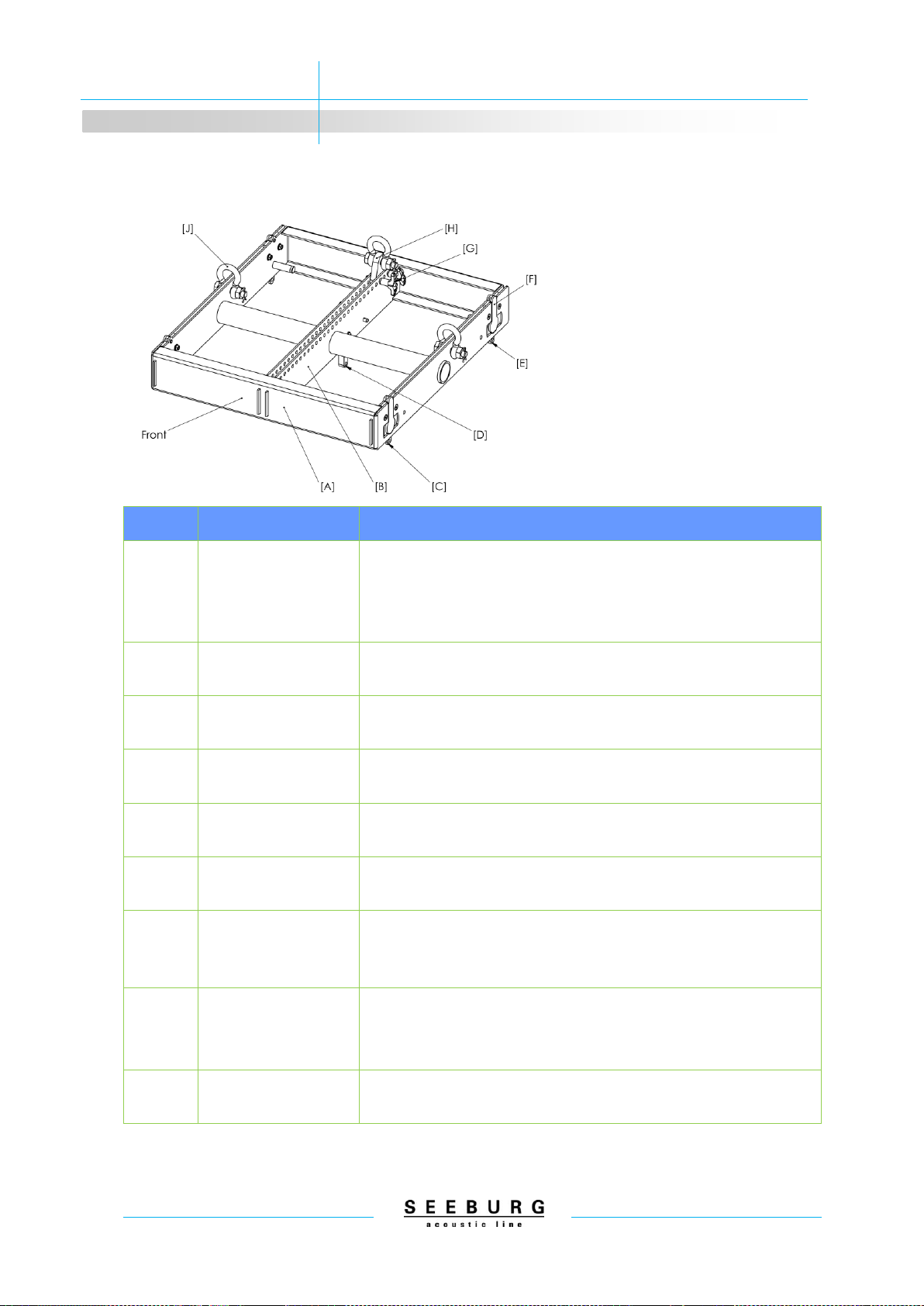
4.1 Galeo S Flying Cradle
Position
Name
Description
A
Galeo S Flying Cradle
(Art. 01312)
For up to 20 flown Galeo S; For up to four stacked Galeo S on the
ground or on top of Galeo S Sub; For up to four Galeo S on a Wind-
Up or a speaker pole on top of a SEEBURG subwoofer
B
Indexed Profile Rails
Perforated profile rails; provides 25 different pinpoint positions to
mount the load adapter [E]
C
Front Links
Front link points; The Snap-Fly connectors of the Galeo S unit are
locked in here; In stacked application the Galeo S is to be mounted
from above and locked with Locking Pins
D
Center Link
Retractable link to connect the uppermost Galeo S unit; Parking posi-
tion is locked with the spare pin
E
Load Adapter
Symmetrical load adapter which is being mounted between the perfo-
rated profile rails [B] by using Locking Pins [G]
Alternatively a Clamp Adapter (Art. 01313) can be used
F
1,5 to Shackle
1.5 t shackle for rigging (e.g. for chain or rope hoists)
G
Locking Pins
Three ball-lock pins 6x20 mm with T-handle; For mounting the load
adapter [E] respectively for rearward connecting with the first Galeo S
unit.
H
M20 Thread
M20 internal thread for mounting a flange with M20 external thread or
a TV spigot with M20 external thread
Galeo S / Galeo S Sub
4 Components of the system
8
4.2 Galeo S Flying Frame
Position
Name
Description
A
Galeo S Flying Frame
(Art. 01310)
For up to 20 flown Galeo S; For up to six stacked Galeo S on the
ground or on top of Galeo S Sub; For up to nine flown Galeo S Sub; For
the connection between flown respectively stacked Galeo S Sub and
Galeo S
B
Indexed Center Rails
Perforated rails; provides 26 different pinpoint positions to mount the
load adapter [H]
C
Front Links
Front link points; The Snap-Fly connectors of the Galeo S or
Galeo S Sub unit are locked in here
D
Center Link
Retractable link to connect the uppermost Galeo S unit; Parking posi-
tion is locked with the spare pin
E
Rear Links
Rear link points; The rear Snap-Fly connectors of the Galeo S Sub unit
are locked in here
F
Snap-Fly Links
Four locking connecting links to mount the Flying Frame under flown
Galeo S Sub respectively for stacking Galeo S on top of Galeo S Sub
G
Locking Pins
Three ball-lock pins 6x20 mm with T-handle; For mounting the load
adapter [H] respectively for rearward connecting with the first Galeo S
unit
H
Load Adapter
Symmetrical load adapter which is being mounted between the perfo-
rated profile rails [B] by using Locking Pins [G]
Alternatively a Clamp Adapter (Art. 01313) can be used
J
1,5 to Shackles
1.5 t shackle for rigging (e.g. for chain or rope hoists), two 1.5 t shackles
at the outside for mounting a safety rope

Galeo S / Galeo S Sub
4 Components of the system
9
4.3 Galeo S (Line Array mid-high unit)
4.3.1 Cabinet
Position
Name
Description
A
Snap-Fly Links
Two locking connecting links to mount the Galeo S unit to the Flying
Frame or to the next Galeo S unit above
B
Front Links
Counter piece to the Snap-Fly links [A]; Connected to the Flying Frame
from above in stacked application
C
Center Link
For rear connection to the next lower Galeo S unit or for connection to
the perforated rail of the Flying Frame in stacked application; Is extend-
ed to the maximum length in the transport position and is getting locked
to the desired length when in use
D
Auto-Locking Hook
Two hooks that latch alternately in to the Center Link [C] to take the
load in a curved array
E
Indexed Center Rails
Perforated rail with 16 holes for the Stop Pin [F] to pre-select the splay
angle between 0° and 15° in one degree steps. For a 16° angle, the
Stop Pin [F] is not inserted. Additional hole at the top of the rail is for the
Link Pin [G]
F
Stop Pin
Stop ball-lock pin 6x20 mm with T-handle; Pin is inserted in the lowest
hole of the perforated rail [E] for transport; Is being plugged (without any
load on it) in the position of the desired splay angle to the next lower
Galeo S unit
G
Link Pin
Link ball-lock pin 6x20 mm with T-handle; Pin is inserted in the upper-
most hole of the perforated rail [E]; For connection to the Center Link of
the Galeo S unit above respectively to a Flying Frame

Galeo S / Galeo S Sub
4 Components of the system
10
4.3.2 AMR-Panels
The coverage of a sound reinforcement system is of primary importance: only a very small part of
the audience is exactly on the axis of one loudspeaker array system. Therefore, we placed a lot of
value during the development of the Galeo S system on an absolutely symmetrical horizontal cov-
erage over the entire frequency range.
The mid-range speakers are covered by AMR-Panels which also function as the horn for the high-
frequency drivers.
Due to the special arrangement, size and shape of the hole, an ideal ratio of sound outlet for the
mid-range and horn guidance for the high range is achieved. The Galeo S is delivered as standard
with horn elements (Art. 08141/100) that provide uniform horizontal coverage over 100°. By replac-
ing the 100° panels with covers with a 70° (Art. 08141/70) horn function, the nominal coverage can
be changed accordingly. This change is particularly appropriate for the uppermost elements of an
array, where the width of coverage is not required and a longer throw is necessary. The front grille
is held by small neodymium magnets and secured by a steel cable (safety).
The vertical coverage is determined by the curving and the tilt of the array (section 6.3)
70° AMR-Panels (Art. 08141/70)
100° AMR-Panels (Art. 08141/100)
The AMR-Panels are mounted directly over the mid-range drivers via four M5 x 30 hex-head
screws.

Galeo S / Galeo S Sub
4 Components of the system
11
4.4 Galeo S Sub (flyable subwoofer)
Position
Name
Description
A
Snap-Fly Links
Four locking connecting links to mount the Galeo S Sub to the Galeo S
Flying Frame or to the next Galeo S Sub above
B
Front/Rear Links
Counter piece to the Snap-Fly links [A]; held in the parking position for
transport with magnets; front and rear position of the links is symmet-
rical for flying cardioids sub arrays
Galeo S / Galeo S Sub
4 Components of the system
12
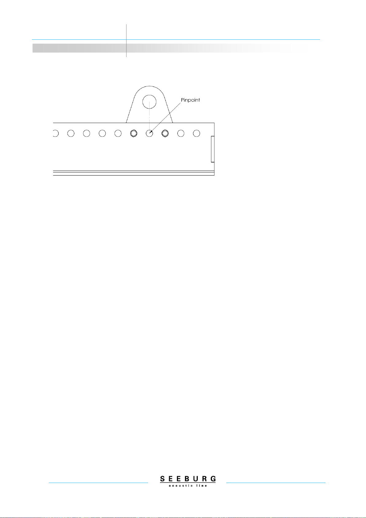
4.5 Definition of the pin point for the load adapter
The load adapter for connecting the Flying Frame to a chain hoist or winch is constructed symmet-
rically to prevent confusion. The pin point calculated by the simulation software EASE Focus 3 is
always the empty hole between the two Locking Pins used to secure the load adapter. This hole is
consequently always directly below the shackle in the load adapter.

Galeo S / Galeo S Sub
5 Permitted loads
13
5Permitted loads
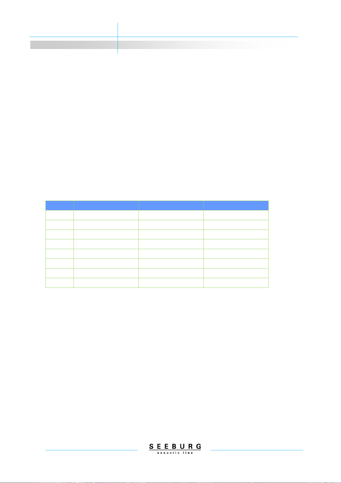
5.1 Galeo S with Galeo S Flying Cradle
The Galeo S Flying Cradle can be used to fly up to a maximum of 20 Galeo S line array units. The
actually permitted number of elements is, however, dependent on the vertical angle (down tilt) of
the array and the pin point in use. The vertical angle is dependent on the length of the array, the
pin point and the curving of the array. The Cradle is always at an angle of 0° to the uppermost
Galeo S element, so therefore the Cradle angle (or Frame angle) is automatically the vertical angle
of the uppermost element in the array.
It is recommended to simulate the desired system configuration using the EASE Focus 3 software
and use the following table to check whether the combination of the number of elements, the pin
point and the maximum downtilt is permissible.
Permitted no. of Galeo S units
Pinpoint
Max. downtilt +/- 5°
Max. downtilt +/- 5-15°
Max. downtilt +/- 15-30°
1 - 18
20
16
11
19
19
16
11
20
18
16
11
21
17
16
11
22
16
16
11
23
15
16
11
24
15
16
11
25
14
14
11
Example: For a flown array of 16 Galeo S units, the pin point must be 22 or lower if the curving of
the array results in a vertical angle of +/- 5°. If the curving results in a vertical angle of between 5°
and 15° (positive or negative), the pin point can be up to 24.
5.2 Galeo S stacked on a Flying Cradle
If a Galeo S array is stacked on a Flying Cradle mounted with a flange (with M20 thread) on a
speaker stand or speaker pole, the maximum permissible number of units is 4. If necessary, the
system has to be secured against tipping over.
Galeo S / Galeo S Sub
5 Permitted loads
14
5.3 Galeo S and Galeo S Sub with Galeo S Flying Frame
The Galeo S Flying Frame can be used to fly up to a maximum of 20 Galeo S line array units, nine
Galeo S Sub or combinations of three Galeo S Sub and nine Galeo S. The actually permitted num-
ber of elements is, however, dependent on the vertical angle (down tilt) of the array and the pin
point in use. The vertical angle is dependent on the length of the array, the pin point and the curv-
ing of the array. The Cradle is always at an angle of 0° to the uppermost Galeo S element, so
therefore the Cradle angle (or Frame angle) is automatically the vertical angle of the uppermost
element/subwoofer in the array.
It is recommended to simulate the desired system configuration using the EASE Focus 3 software
and use the following table to check whether the combination of the number of elements, the pin
point and the maximum downtilt is permissible.
Permitted no. of Galeo S
Pinpoint
Max. downtilt +/- 5°
Max. downtilt +/- 5-15°
Max. downtilt +/- 15-30°
1 - 19
20
20
20
20
20
20
19
21
20
20
18
22
20
20
17
23
20
20
16
24
20
20
15
25
20
20
15
26
20
20
14
Example: For a flown array of 16 Galeo S units, the pin point must be 23 or lower if the curving of
the array results in a vertical angle between 15° and 30° (positive or negative).

Galeo S / Galeo S Sub
5 Permitted loads
15
5.4 Weight overview
Galeo S
No. of Galeo S units
Weight incl. Cradle
Weight incl. Frame
1
16,10 kg
21,50 kg
2
29,60 kg
35,00 kg
3
43,10 kg
48,50 kg
4
56,60 kg
62,00 kg
5
70,10 kg
75,50 kg
6
83,60 kg
89,00 kg
7
97,10 kg
102,50 kg
8
110,60 kg
116,00 kg
9
124,10 kg
129,50 kg
10
137,60 kg
143,00 kg
11
151,10 kg
156,50 kg
12
164,60 kg
170,00 kg
13
178,10 kg
183,50 kg
14
191,60 kg
197,00 kg
15
205,10 kg
210,50 kg
16
218,60 kg
224,00 kg
17
232,10 kg
237,50 kg
18
245,60 kg
251,00 kg
19
259,10 kg
264,50 kg
20
272,60 kg
278,00 kg
Galeo S Sub
No. of Galeo S Sub
Weight incl. Frame
1
41,00 kg
2
74,00 kg
3
107,00 kg
4
140,00 kg
5
173,00 kg
6
206,00 kg
7
239,00 kg
8
272,00 kg
9
305,00 kg
Galeo S / Galeo S Sub
6 Transport and preparation
16
6Transport and preparation
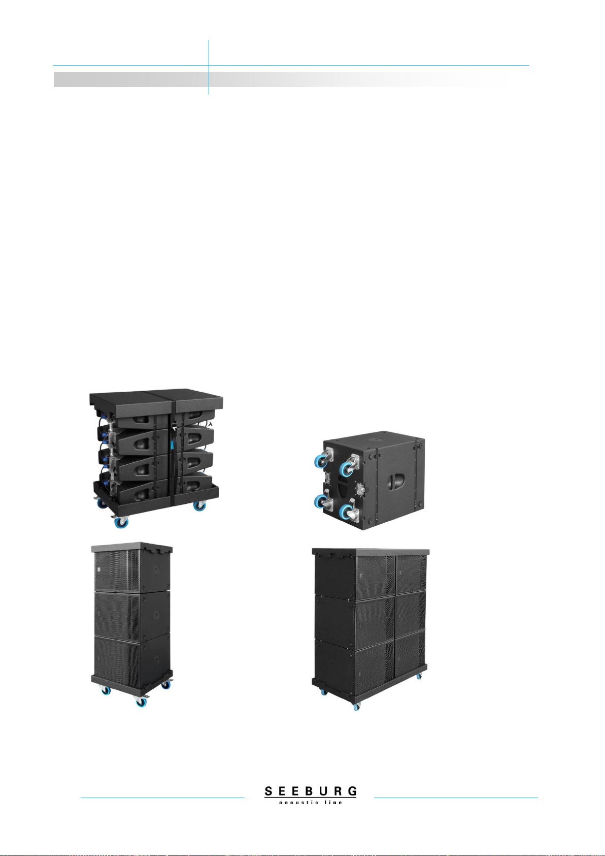
6.1 Transport in Galeo S/Galeo S Sub dolly
Galeo S units are transported as a vertical stack with the elements linked and the splay angle set
to 0°. The Galeo S dolly carries multiples of 2 Galeo S units. The recommended maximum number
of elements is 12; otherwise the dolly may be unstable and prone to tipping over.
The top cover of the dolly must be secured to the lower part using a ratchet strap.
Transport of the Galeo S Sub is possible using the wheel-boards with cover, the single dolly or the
double dolly. The recommended maximum is 3 Galeo S Subs on a single dolly or 6 on a double
dolly. Exceeding the recommended maximum may cause the dolly to be unstable and prone to
tipping over.
The top cover of the subwoofer dolly must also be secured with a ratchet strap.
Galeo S units in dolly, Galeo S Sub with wheel-board, Galeo S Subs in single- and in double dolly

Galeo S / Galeo S Sub
6 Transport and preparation
17
6.2 General preparations and checks
Make yourself familiar with the relevant dimensions of the venue and plan the arrays in the EASE
Focus 3 software. The software calculates the position of the pick point, the pin point for the load
adapter on the Frame, the splay angles between the array elements and the total vertical angle
(down tilt) of the array.
Before installation, assure the perfect condition of all rigging points, hoists and winches. Make sure
the position is correct, and ensure there is enough free area to work safely. Check that all the ma-
terial to be used for the installation is suitable and certified for the intended use, and has been sub-
jected to all pertinent checks.
Check the condition of all components of the integrated flying hardware, the Flying Frame or Cra-
dle, and all adapters. If you have even the slightest doubt about the condition of any component,
DO NOT USE IT. Change the component for one whose condition is without any doubt.
Make sure that the material and rigging points to be used have sufficient load bearing capacity for
the weight of the planned array, and are certified. The weight of the array components can be
found in the calculation in the EASE Focus 3 software or in the table in section 5 of this manual.
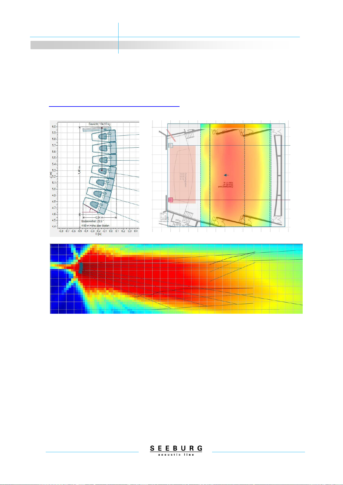
6.3 Simulation with EASE Focus 3
Use the EASE Focus 3 software to make an acoustic and mechanical simulation of the Galeo S
System. The software is available for download on our internet site in the download section under
“software” (https://www.seeburg.net/en/downloads). The software allows easy simulation of how
the Galeo S array must be tilted and angled to provide ideal coverage of the audience area. Whilst
using the software, take heed of any warnings which the software may show, and check the data
which is generated by the software for plausibility.
The best results for coverage and reach are generally achieved when the line array is aimed rela-
tively flat over the heads of the public, and is not hung too high. Try and keep the splay angles in
the array as small as possible, and use the Auto-splay function in the software. The lowest element
in the array should be just above the heads of the persons on the stage. The array can then be
hung with small angles between the elements, allowing the most benefit from the acoustic coupling
between the single array elements (cylindrical wave front). Additionally, less time and effort is re-
quired for the rigging when the array is flown from a single point. More vertical angle than can be
achieved with setting the load adapter in position 20 on the Flying Cradle or in position 26 on the
Flying Frame is not permissible. Observe at all times the load limits specified in the section 5 of this
manual.
Galeo S / Galeo S Sub
6 Transport and preparation
18
Even small deviations in the vertical angle of the array or the curving can have a very strong influ-
ence on the quality of the acoustic result.
General information about using EASE Focus is available in the internet at:
https://focus.afmg.eu/index.php/fc-software-en.html
Simulation example EASE Focus 3

Galeo S / Galeo S Sub
7 Installing the line array system
19
7Installing the line array system
7.1 Mounting the load adapter
The load adapter is mounted in the Cradle or Frame in the required position using two Locking
Pins. Information about positioning the load adapter and a definition of the pin point can be found in
section 4.5 of this manual. The mounting hole in the load adapter is suitable for shackles with a
rating of up to 1.5 t.
7.2 Mounting Galeo S to the Flying Cradle or Flying Frame
First of all the Snap-Fly links are pulled out a bit and then turned to the side. The Link Pin of the
uppermost Galeo S unit is also removed. The Flying Cradle or Frame is set onto the array from
above, and the Snap-Fly links rotated in and locked into place. The Center Link of the Flying Cradle
or Frame is connected to the Center Rail of the uppermost Galeo S unit with a Link Pin in the up-
permost hole in the Center Rail. Pay attention that the Snap-Fly links are properly locked in to the
front links of the component above such that they sit flush to the side of the cabinet and are not
standing out of the side surface.
7.3 Flying and securing the Galeo S
The Galeo S system is flown using an appropriate shackle (up to 1.5 t) mounted to the load adapt-
er. The shackle is hung using appropriate lifting accessories (steelflex, sling, chain hoist, winch,
etc.). All relevant safety regulations that are customary in the country must be observed at all
times.
The system is additionally secured using a non-
flammable safety cable (e.g. steel cable, chain) with
sufficient load bearing capacity. This material must
also meet the requirements of all relevant safety regu-
lations. The Flying Frame has a hole in each side rail
which will accept shackles for this purpose. When
using the Flying Cradle, the safety cable should be
secured with a second load adapter or with 2 M10 eye
screws mounted in the flying points on the uppermost
Galeo S element.

Galeo S / Galeo S Sub
7 Installing the line array system
20
7.4 Mounting addidtional Galeo S units
Additional Galeo S units are mounted to the array following the same principle as for mounting to
the Flying Frame or Cradle (see section 7.2) using the Snap-Fly links at the front and the Center
Link at the rear.
7.5 Setting splay angles and lifting in operation position
When the array is flown, the Stop Pins on the rear of the Galeo S elements, which specify the splay
angles, are not under load. They can be removed from the 0° position and placed in the position
required for the desired splay angle. The uppermost Galeo S unit, which is connected to the Flying
Cradle or Flying Frame, always has a splay angle of 0° for mechanical reasons.
The angles for the rest of the Galeo S units are set by placing the Stop Pin in the hole for the re-
quired splay angle for each element in the Indexed Center Rail of the next highest element. This
should be done for all Galeo S units in the array before the curving is done.
Presetting the desired splay angles in flown, not curved array
This manual suits for next models
1
Table of contents
Other Seeburg Subwoofer manuals


