Seeed ODYSSEY X86 User manual

ODYSSEY X86 User Manual
Getting Started with ODYSSEY X86
ODYSSEY X86 v2 board powered by the latest Intel® Core™ 11th Gen. processor
and Intel® UHD Graphics or Intel® Iris Xe Graphics, which delivers high CPU and
AI performance for various applications. It has two high-speed 2.5-Gigabit
Ethernet ports and supports hybrid connectivity including, BLE and WIFI.
Meanwhile.
Features
Powered by the latest 11th Gen Intel® Core™ CPU and Intel® UHD Graphics
or Intel® Iris Xe Graphics.
Rich peripherals including dual® 2.5-Gigabit Ethernet ports, USB 3.2 Type-A
port, USB 2.0 Type-A port, HDMI port and DP port

Support hybrid connectivity including BLE and WIFI
Dual SATA III 6.0 Gbps data connectors for 3.5"/2.5" SATA hard disk drives
with enough space inside the enclosure to store them both
M.2 B-Key/ M-Key/ E-Key for expandability such as SSD, WIFI
Pre-installed Windows 10 Enterprise (Unactuated), also support another
Windows OS and Linux OS
Specification

Comparison
Quick Start with ODYSSEY X86
If you want to get started with ODYSSEY X86 in the fastest and easiest way, you can
follow the guide below.
Hardware Required
You need to prepare the following hardware before getting started with ODYSSEY
X86。
ODYSSEY X86
Power Adapter(provided)
External monitor
HDMI/DP cable
Keyboard and Mouse
Hardware Installation
For this part, we will introduce how to install or replace some hardware inside
ODYSSEY X86. If there are no needs for you, please skip it. You might follow the

Assembly Guide Manual attached at the end of this page to access to the main
board of ODYSSEY X86 before reading this part.
DDR4 Installation
DDR4-3200MT/s has been pre-installed for all versions of ODYSSEY X86 but you
can also add a new DDR4 to the other channel or replace the pre-installed one with
your own to expand memory. The dual-channel SO-DIMM slots support DDR4-
3200MT/s up to 64GB in total.
SSD Installation
A NV Me SSD has been pre-installed for all versions of ODYSSEY X86, while, still, the
M.2 M-Key 2242/2280(PCIe 3.0 x4) allows you to replace it with the SSD you desire.

WIFI Module Installation
All versions of ODYSSEY X86 have installed 2230 Dual Band WIFI AX201 Module
at M.2 E-Key 2242/2280(PCIe 3.0x4). If you want to replace the pre-installed WIFI
Module, feel free to follow the steps below.
Step 1. Remove the SSD from M.2 M-Key slot.
Step 2. Take off the WIFI antenna cable and remove the pre-installed WIFI Module
from M.2 E-Key.

Step 3. Install the new WIFI Module and connect the WIFI antenna cable back to it.
Step 4. Install the SSD back to M.2 M-Key.
Hardware Connection
For this part, we will introduce the interface connection of ODYSSEY X86. There are
two versions of ODYSSEY X86. Please note that different versions might have
different interfaces.
Display Connection
There are three methods for ODYSSEY X86 to connect to a display while the third
method is only for High-performing versions.
Method 1. HDMI Port、
Method 2. DP Port
Keyboard and Mouse Connection
Connect keyboard and mouse through USB ports. There are one USB 3.2 port and

one USB 2.0 port for Basic versions while there are one USB 3.2 port and two USB
2.0 ports for High-performing versions. Basic version
Audio Connection
For Basic versions, the Audio Jack is on the left side I/O panel, while, for High-
performing versions, it's on the right side I/O panel for High-performing versions
Power Connection
There are two methods to power up ODYSSEY X86, and the second one is only for
High-performing versions.
Method 1. Simply connect AC-DC power adapter (included in the product box) with
AC power cord (Out of the product box but still in the package), then connect it to
12V DC Jack of ODYSSEY X86.
Method 2. Connect USB Type-C charging cable (Not included in ODYSSEY X86) to
the Thunderbolt 4 USB Type-C port (This port is only available with High-performing
versions)
Operation System Installation
For all versions of ODYSSEY X86, Windows 10 Enterprise (Unactuated) has been pre-
installed, you can simply boot it up and activate the OS. However, ODYSSEY X86 still
supports another Windows OS and, also, Linux OS, so you can cover the pre-
installed OS with the one you want.
Note: 5G Band(W52): indoor use only

FCC Statement
This equipment has been tested and found to comply with the limits for a Class B digital
device, pursuant to part 15 of the FCC Rules. These limits are designed to provide reasonable
protection against harmful interference in a residential installation. This equipment generates,
uses and can radiate radio frequency energy and, if not installed and used in accordance with
the instructions, may cause harmful interference to radio communications. However, there is
no guarantee that interference will not occur in a particular installation. If this equipment does
cause harmful interference to radio or television reception, which can be determined by
turning the equipment off and on, the user is encouraged to try to correct the interference
by one or more of the following measures:
• Reorient or relocate the receiving antenna.
• Increase the separation between the equipment and receiver.
• Connect the equipment into an outlet on a circuit different from that to which the receiver
is connected.
• Consult the dealer or an experienced radio/TV technician for help.
Caution: Any changes or modifications to this device not explicitly approved by manufacturer
could void your authority to operate this equipment.
This device complies with part 15 of the FCC Rules. Operation is subject to the following two
conditions: (1) This device may not cause harmful interference, and (2) this device must accept
any interference received, including interference that may cause undesired operation.
RF Exposure Information
This equipment complies with FCC radiation exposure limits set forth for an uncontrolled
environment. This equipment should be installed and operated with minimum distance 20cm
between the radiator and your body.
This transmitter must not be co-located or operating in conjunction with any other antenna
or transmitter.
This device is intended only for OEM integrators under the following conditions:
1. The antenna must be installed such that 20cm is maintained between the antenna and
users, and
2. The transmitter module may not be co-located with any other transmitter or antenna.
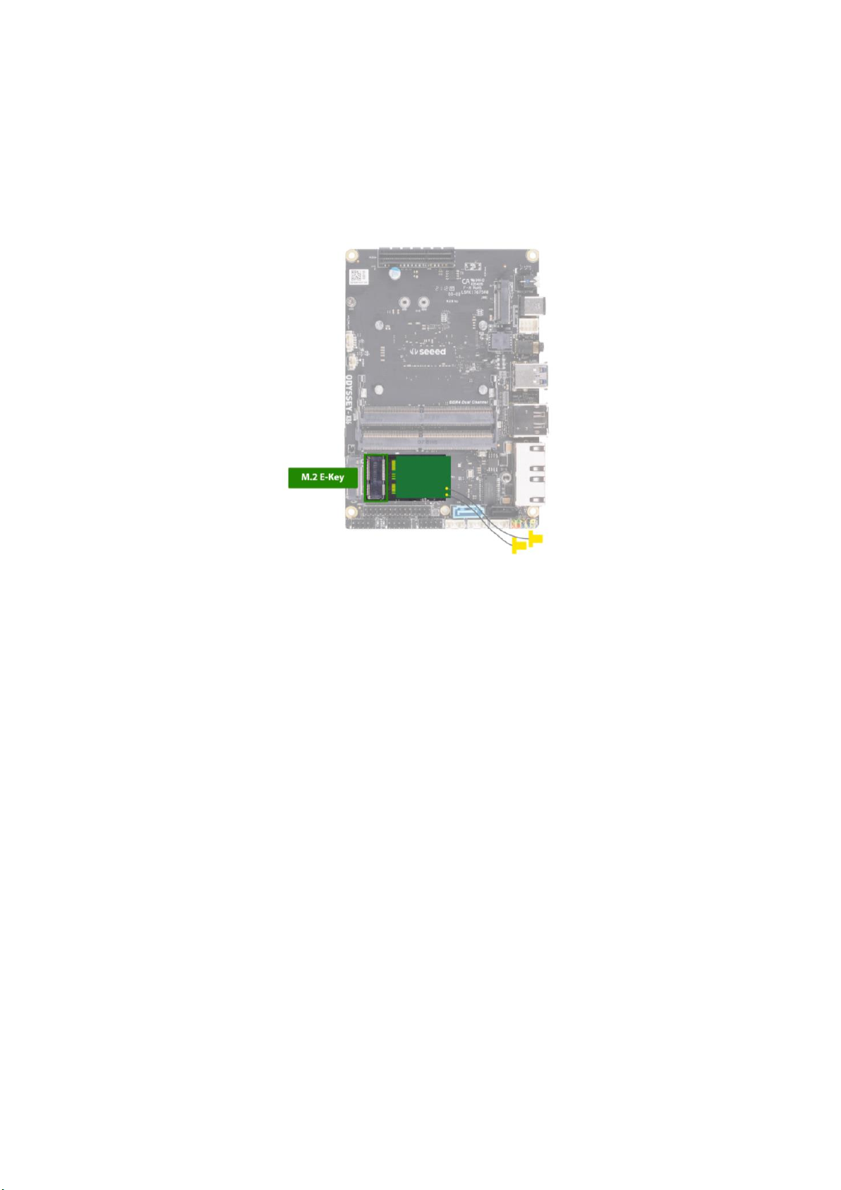
The internal antenna and external rod antenna has been approved for the modular. The
maximum antenna gain are 2.13dBi (BT/2.4G Wi-Fi Antenna 1 & 2: External Antenna)
& 1.57dBi (5.2G & 5.8G Wi-Fi Antenna 1 & 2: External Antenna). For situations where the
host manufacturer is responsible for an external connector, the integration instructions shall
inform the installer that a unique antenna connector must be used on the Part 15
authorized transmitters used in the host product.
Important Note: In the event that these conditions cannot be met (for example certain laptop
configurations or co-location with another transmitter), then the FCC authorization is no

longer considered valid and the FCC ID cannot be used on the final product. In these
circumstances, the OEM integrator will be responsible for re-evaluating the end product
(including the transmitter) and obtaining a separate FCC authorization.
Any company of the host device which install this modular with limit modular approval should
perform the test of radiated emission and spurious emission according to FCC part 15C:
15.247 and 15.407 requirement, only if the test result comply with FCC part 15.247 and 15.407
requirement, then the host can be sold legally.
End Product Labeling
If the FCC identification number is not visible when the module is installed inside another
device, then the outside of the device into which the module is installed must also display a
label referring to the enclosed module. This exterior label can use wording such as the
following: Contains Transmitter Module FCC ID: Z4T-ODYSSEY-A.
Manual Information to the End User
The OEM integrator has to be aware not to provide information to the end user regarding
how to install or remove this RF module in the user’s manual of the end product which
integrates this module.
The end user manual shall include all required regulatory information/warning as show in this
manual.
The modular is not intended to be fielded serviceable as without shielding, host manufacturer
must be considered shielding when integrating a module.
When the module is installed inside another device, the user manual of this device must
contain below warning statements;
This device complies with Part 15 of the FCC Rules. Operation is subject to the following two
conditions:
(1) This device may not cause harmful interference.
(2) This device must accept any interference received, including interference that may cause
Changes or modifications not expressly approved by the party responsible for compliance
could void the user's authority to operate the equipment. The devices must be installed and
used in strict accordance with the manufacturer's instructions as described in the user
documentation that comes with the product.
Table of contents
Other Seeed Desktop manuals
Popular Desktop manuals by other brands

Lenovo
Lenovo ThinkCentre Edge 92z Vodič za uporabnika

Fujitsu Siemens Computers
Fujitsu Siemens Computers SCALEO EVi 2565 datasheet

Lenovo
Lenovo ThinkCentre Chromebox Hardware Maintenance Manual

VIA Technologies
VIA Technologies AMOS-820 SKU user manual

Dell
Dell OptiPlex N7132 Quick reference guide

Lenovo
Lenovo ThinkCentre M80 user guide