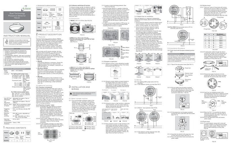
Seen IRIS 860 Sensor User manual

© Copyright 2023 Seen Safety | SEEN Safety System Installation Guide | Version 231205 | seensafety.com/resources 1
INSTALLATION GUIDE
SEEN IRIS 860 sensor
SEEN IRIS 860 Cab Box
SEEN IRIS-i camera
This guide contains instructions and
information to support the installation of
SEEN System products, including the IRIS
860 sensor and IRIS-i camera.

© Copyright 2023 Seen Safety | SEEN Safety System Installation Guide | Version 231205 | seensafety.com/resources 2
Contents
Installation Instructions
IRIS 860 sensor
Introduction 5
Mounting 7
Sensor wiring 9
Testing 10
Troubleshooting 11
IRIS 860 Cab Box
Introduction 13
Wiring 14
Testing 15
Troubleshooting 15
IRIS 860 Weather Shield 17
IRIS-i camera
Introduction 19
Serial Number Record 20
Installation 21
Antenna 23
LED indications 23
IRIS 860 accessories
Bluetooth Dongle 24
Buzzer Cap 25
Machine templates
Introduction 26
Sit-down Counterbalance Forklift 27
Stand-up Counterbalance Forklift 28
Reach Truck 29
Sensor settings
Sensor settings 30
How to change the settings 31
Technical reference resources
Using a DC/DC converter 33
Connect a third party accessory 35
Sensor internal self check function 37
Changing settings via Cab Box Sensor Cable 38
Cab Box cable shortening and threading 39
IRIS-i camera Internal memory 40
Product Specifications
IRIS 860 sensor 42
IRIS 860 Cab Box 44
IRIS-i camera 46
General
Warranties 48
Maintenance 49
Support 49

© Copyright 2023 Seen Safety | SEEN Safety System Installation Guide | Version 231205 | seensafety.com/resources 3
IMPORTANT
SEEN IRIS 860 sensors can provide collision warning assistance to the operator but do not
replace the need for proper operator training and best practice safe operating procedure.
While IRIS 860 sensors can alert the machine operator to a potential collision, the operator
is always fully responsible for the safe operation of the equipment. IRIS 860 sensors do not
comply with the regulatory standards required for devices which are intended to directly
control vehicle or machine safety functions. Using the sensor accessory port to control a
vehicle or machine function is entirely at your own risk. Detection can never be guaranteed.
IRIS 860 sensors are a CLASS I LASER PRODUCT. Disassembly or modification of this device
may result in hazardous radiation exposure.
IRIS 860 sensors and accessories have no user serviceable parts. Opening the enclosure will
void the warranty.

© Copyright 2023 Seen Safety | SEEN Safety System Installation Guide | Version 231205 | seensafety.com/resources 4
SEEN IRIS 860 sensor
INSTALLATION GUIDE
For additional resources about the
SEEN Safety system, please refer to
www.seensafety.com/resources.

© Copyright 2023 Seen Safety | SEEN Safety System Installation Guide | Version 231205 | seensafety.com/resources 5
Introduction
IRIS 860 sensor
SEEN IRIS 860 sensors are designed for use on heavy mobile
equipment like forklifts and wheel loaders. The sensor uses
non-visible infrared laser light to detect the presence of retro-
reflective material, such as the reflective tape found on day/
night high visibility PPE and markers. Detection is indicated
by an audible alert.
The detection zone and alert volume can be changed to suit
the operating environment.
Before you start installation
1. Read the installation instructions in full before starting.
2. Ask the customer for their Machine template, which
specifies where the sensor should be installed on the
machine, and how it should be set up.
If the customer doesn’t have a template, please refer to
SEEN’s generic Machine Templates on page 26, which
outline recommended mounting specifications for a
variety of common machine types.
3. Before going on-site, ensure you have an exact plan
of how you will mount the sensor(s) and any custom
mounting attachments, if required.
Related section
Sensor mounting location - Pg. 7
Machine Templates - Pg. 26
Check the vehicle’s power supply voltage against the IRIS
860 sensor maximum voltage rating sticker and use a DC/
DC converter if necessary.
Related section
Using a DC/DC voltage converter - Pg. 33
4. Check with the customer whether any additional
accessories need to be installed. These may include a
Weather Shield, Cab Box, and IRIS-i camera.
You will need a SEEN Bluetooth Dongle (P/n SI-138)
to apply the sensor settings specified in the Machine
Template.
IRIS 860 sensor

© Copyright 2023 Seen Safety | SEEN Safety System Installation Guide | Version 231205 | seensafety.com/resources 6
Accessory socket
Power socket
Alert buzzer
IRIS 860 sensor front IRIS 860 sensor back
IRIS 860 sensor mounted in bracket with power cable
attached.
Sensor box contents
• 1 x IRIS 860 sensor
• 1 x stainless steel mounting bracket
• 1 x power cable 4m (13ft)
• 4 x stainless screws (M6)
LED light
IRIS 860 sensor parts
Sensor box contents
IRIS 860 sensor
Sensor maximum
voltage rating sticker

© Copyright 2023 Seen Safety | SEEN Safety System Installation Guide | Version 231205 | seensafety.com/resources 7
Mounting
1. Sensor mounting location
The sensor’s mounting location, angle, and settings should be
specified by the customer in a Machine Template.
If one is not available, please refer to SEEN’s generic Machine
Templates on page 26. These detail the recommended IRIS
860 mounting specifications for a variety of common machine
types.
Related section
Machine Templates - Pg. 26
Make sure that the sensor is protected against impact. If the
forklift works inside containers, ensure the sensor does not
protrude above the highest point of the frame.
A custom mounting attachment may be needed to attach
the IRIS 860 mounting bracket in the desired position.
35mm
130mm
70mm
Sensor mounting bracket
UnderOver Vertical
2. Sensor bracket orientation
The supplied mounting bracket can be used on horizontal,
vertical, or angled surfaces. Select the bracket orientation that
best suits the installation requirements.
3. Attach the mounting bracket to the
machine
Securely bolt the mounting bracket to a solid surface using at
least two appropriate M6 fasteners.
WARNING. Do not drill into any roll-over or falling-
object protection structure (ROPS / FOPS) as this may
compromise the strength of the structure and void the
machine warranty.
IRIS 860 sensor

© Copyright 2023 Seen Safety | SEEN Safety System Installation Guide | Version 231205 | seensafety.com/resources 8
4. Mount the sensor in the bracket
If a Weather Shield is used, it needs to be installed at this
stage.
Related section
Weather Shield installation - Pg. 17
Machine Templates - Pg. 26
• Align the sensor’s four mounting holes with the slots in
the mounting bracket.
• Insert each M6 screw (supplied) and finger-tighten.
• Adjust the sensor to the correct angle. The figure on the
alignment sticker should be upright.*
• Tighten the four M6 mounting screws to 10Nm.
CHECK. Check that the sensor is the right way up and that
the figure on the alignment sticker in upright*.
*If the sensor is mounted higher than approximately 2m (6.5ft)
It may need to be angled slightly further towards the ground. *
80V max
The alignment sticker is found on the
side of the sensor.
IRIS 860 sensor

© Copyright 2023 Seen Safety | SEEN Safety System Installation Guide | Version 231205 | seensafety.com/resources 9
M12 connectors.
Finger tighten only.
Do not use tools.
Wiring
If a Cab Box is being installed (required for closed-cab
machines), skip to Cab Box installation on page 13.
Related sections
Cab Box installation - Pg. 13
Using a DC/DC voltage converter - Pg. 33
Troubleshooting - Pg. 11
1. Check the sensor voltage
Check the sensor’s maximum voltage rating sticker. It will
either be 24V or 80V.
If the vehicle’s power supply exceeds the maximum voltage
indicated on the sticker, a DC/DC voltage converter must be
used.
2. Wire in the Sensor Power Cable
IMPORTANT. Ensure the vehicle is turned o before
starting work.
The 4-PIN, 4m (13ft) Sensor Power Cable must be connected
to the vehicle’s electrical power supply. The following three
wires must be connected:
BROWN (Power)
The Brown wire must continuously receive DC power
when the vehicle is on. A DC/DC voltage converter may
be needed.
BLACK (Direction signal) DC 3.5-100V 1mA
The Black wire must be connected to the vehicle’s
direction signal (in most cases the reverse signal). The
reverse signal must be continuous (not pulsed) while
the vehicle is in reverse gear. Ensure the voltage on the
Black wire is less than +1V when the direction signal is
not high.
3. BLUE (Ground)
The Blue wire must be connected to the vehicle’s
ground.
Once the Sensor Power Cable is wired to the vehicle, carefully
connect the M12 plug connector to the sensor’s 5-PIN M12
power socket. Finger-tighten only.
80V max
80V max
The sensor’s maximum
voltage rating sticker
will be either 24V or
80V.
IRIS 860 sensor

© Copyright 2023 Seen Safety | SEEN Safety System Installation Guide | Version 231205 | seensafety.com/resources 10
Testing
Related sections
Troubleshooting - Pg. 11
Sensor settings - Pg. 30
Once installed the sensor must be tested to ensure it works
correctly.
SAFETY FIRST. For your safety ensure the vehicle engine
is o and the park-brake is on at all times.
Check the mounting angle
Check that the face of the sensor is angled down correctly,
and that the figure on the alignment sticker is upright.
Test the power supply
Switch the vehicle on. The sensor should have a steady
green LED while the machine is switched on.
Test the reverse signal connection*
Note. If the factory default settings have been changed,
the functionality may dier from that described below.
Test Method:
1. Place a retro-reflective safety vest (or similar) in the
sensor’s detection zone (approximately 2-3 meters
from the sensor). The sensor should not alert.
2. Now, put the vehicle in reverse and repeat the test.
This time the sensor should alert.
When the sensor alerts, the LED will turn red and the
sensor will emit a loud audible tone.
*By default IRIS 860 sensors are factory pre-set so they
can only alert while receiving a direction signal (usually the
reverse signal) from the vehicle. This setting can be changed
using the Sensor Setup App and SEEN’s Bluetooth Dongle.
Related section
How to change the sensor settings - Pg. 31
The sensor LED should be green while
the vehicle is powered on.
IRIS 860 sensor

© Copyright 2023 Seen Safety | SEEN Safety System Installation Guide | Version 231205 | seensafety.com/resources 11
Troubleshooting
1. The sensor LED is green, but the sensor will not
alert.
Possible cause: No reverse signal present. By default
sensors are set so they can only alert while receiving a
direction signal (usually reverse) from the machine. Check
the black wire is connected to the vehicle’s reverse signal.
Possible cause: The retro-reflective material is too close
to the sensor. Move further back. Detection starts 0.8m
/2.6ft from the sensor face.
Possible cause: The retro-reflective material is worn out
or is of insuicient size to enable detection.
Related Resources
seensafety.com/resources/reflective-tape-requirements
2. A sensor that is set so that it can only alert during
reverse, will alert when the vehicle is not in reverse.
Possible cause: The reverse signal input wire (black) is
twisted together with the power wire, meaning the reverse
signal is always high. Connect the black wire to the reverse
signal.
Possible cause: Voltage issue on the reverse signal. The
reverse signal input (black) must have no more than +1V
when it not high, and more than 3.5V when it is high.
3. The sensor is correctly wired but the sensor/s do
not behave in the expected way.
Possible cause: An electrical earthing issue on the reverse
signal. Check that the ground reference on the reverse
signal is the same as the ground reference on the sensor
power supply. Also refer to point 7.
4. The sensor repeatedly beeps and flashes with the
sequence long-short-short, long-short-short.
Cause: Blocked window. Clean the windows and the self-
check alert should cease. If the sensor is operating in a
cold-store freezer, ice on the window maybe triggering the
self checking function. Contact SEEN Support.
6. The sensor is beeping and flashing and the
sequence is NOT long-short-short, long-short-
short.
Cause: Internal fault detected. There are no user
serviceable parts. Contact your supplier.
IRIS 860 sensor

© Copyright 2023 Seen Safety | SEEN Safety System Installation Guide | Version 231205 | seensafety.com/resources 12
Reverse signal
(center)
Sensor Power Cable
Ignition power
Orientation slot
Ground
7. Direction signal grounding issue.
Applies to a sensor connected to a direction signal input
(usually reverse). If a DC/DC converter is used refer to
page 33.
Note: In this example the direction signal is REVERSE.
Problem: The sensor is correctly powered and connected
to the reverse signal, but the sensor does not alert even
when the reverse signal is active. The reverse signal and
sensor power supply may not share a common ground.
To check the reverse signal ground:
• Unplug the sensor power cable
• Switch the vehicle ignition ON (preferably without
starting the vehicle for safety)
• Attach a voltmeter across the ignition power pin (+)
and the ground pin (–) of the power cable. The voltage
should be between +10V and +29V. Refer to the plug
diagrams opposite.
• Next, attach the voltmeter across the reverse direction
pin and the ground pin (–). When the vehicle is NOT in
reverse, the voltage should measure between 0V and
+1V. When the vehicle IS in reverse it should measure
between +3V and +100V.
If the vehicle is in reverse and the voltage is not 3-100V
between the ground pin (–) and the reverse direction pin,
there may be a grounding issue.
IRIS 860 sensor

© Copyright 2023 Seen Safety | SEEN Safety System Installation Guide | Version 231205 | seensafety.com/resources 13
IRIS 860 Cab Box
INSTALLATION GUIDE
Introduction
Before you start
Check the vehicle’s power supply voltage against the Cab
Box’s maximum voltage rating and use a DC/DC converter if
necessary.
Purpose
On an enclosed cabin vehicle, the Cab Box provides an audible
alert to the operator inside the cab. Up to four sensors can be
connected to each Cab Box.
Components
• Cab Box
Installed in the driver’s cab
• Cab Box Power Cable
Connects to the vehicle’s power supply and direction
signal. (4pin cable included with each Cab Box)
• Cab Box Sensor Cable
Used to connect the sensor back to the Cab Box.
Available in lengths of 5m (16ft), 10m (33ft), 15m (50ft) or
20m (65ft).
IRIS 860 sensor
Cab Box
Cab Box Sensor
Cable
Cab Box
installation
example:
Cab Box
Sensor Cable
4-PIN Cab Box
Power Cable
Cab Box
IRIS 860 sensor
Cab Box

© Copyright 2023 Seen Safety | SEEN Safety System Installation Guide | Version 231205 | seensafety.com/resources 14
Wiring
1. Check the voltage
If the vehicle’s power supply exceeds 24V a DC/DC voltage
converter must be used.
Related section
Using a DC/DC Converter - Pg. 33
The Cab Box may draw up to 4.0A.
2. Connect Cab Box Power Cable
IMPORTANT. Only use the 4-PIN Cab Box Power Cable
provided with the Cab Box. Do not use the sensor 5-PIN
power cable which is not needed for Cab Box installations.
Wire the 4-PIN, 4m (13ft) Cab Box Power Cable to the vehicle:
BROWN (Power) DC 12-24V 4A
The Brown wire must continuously receive DC power
when the vehicle is switched on. A DC/DC voltage
converter may be needed.
BLACK (Direction signal) DC 3.5-100V 1mA
The Black wire must be connected to the vehicle’s
direction signal (in most cases the reverse signal). The
reverse signal must be continuous (not pulsed) while
the vehicle is in reverse gear. Ensure the voltage on the
Black wire is less than +1V when the direction signal is
not high.
BLUE (Ground)
The Blue wire must be connected to the vehicle’s
ground.
3. Connect Cab Box Sensor Cable
Connect each sensor to the Cab Box using the Cab Box
Sensor Cable. One end of the cable has a re-wireable plug that
can be removed to assist the threading of the cable through
the machine chassis or to shorten the cable.
Related section
Cab Box Sensor Cable shortening and threading - Pg. 39
Moulded end
(Attach to sensor)
Re-wireable plug
(Attach to Cab Box)
Cab Box Sensor Cable
5/10/15/20m length
4-PIN Cab Box Power Cable
Cab Box
M12 connectors.
Finger tighten only.
Do not use tools.
Cab Box

© Copyright 2023 Seen Safety | SEEN Safety System Installation Guide | Version 231205 | seensafety.com/resources 15
Testing
The Cab Box alert mirrors the LED and audible alert state of
its connected sensor/s.
• When the vehicle is first switched on the sensor will Boot,
indicated by a single beep and red LED flash followed by
a steady green LED on the sensor and Cab Box.
• While the vehicle is on the sensor and Cab Box should
have a steady green LED.
• When the sensor is detecting the sensor and Cab Box will
have an audible alert and red LED*.
*By default IRIS 860 sensors are factory pre-set to only detect
if they are receiving a direction (usually reverse) signal from
the vehicle. This setting can be changed in the Sensor Setup
App,
Related section
How to change the sensor settings - Pg. 31
Troubleshooting
1. The Cab Box is correctly wired but the connected
sensor/s do not behave in the expected way.
Possible cause: Wrong power cable. Ensure you use the
4 PIN Cab Box power cable supplied with the Cab Box. Do
not use the 5 PIN sensor power cable supplied with each
sensor.
2. Direction signal grounding issue.
Applies to a Cab Box connected to a direction signal input
(usually reverse). If a DC/DC converter is used refer to
page 33.
Note: In this example the direction signal is REVERSE.
Problem: The Cab Box is correctly powered and
connected to the reverse signal, but the sensor does not
alert even when the reverse signal is active. The reverse
signal and sensor power supply may not share a common
ground.
To check the reverse signal ground:
• Unplug the sensor or Cab Box power cable
• Switch the vehicle ignition ON (preferably without
starting the vehicle for safety)
• Attach a voltmeter across the ignition power pin (+)
and the ground pin (–) of the power cable. The voltage
should be between +10V and +29V. Refer to the plug
diagram opposite.
Cab Box Power
Cable
2 x Cab Box Sensor Cables are
shown attached. The green
LED indicates that a sensor is
attached.
Cab Box
Reverse
Signal
Cab Box Power Cable
Ignition power (+)
Orientation slot
Ground (–)

© Copyright 2023 Seen Safety | SEEN Safety System Installation Guide | Version 231205 | seensafety.com/resources 16
• Next, attach the voltmeter across the reverse direction
pin and the ground pin (–). When the vehicle is NOT in
reverse, the voltage should measure between 0V and
+1V. When the vehicle IS in reverse it should measure
between +3V and +100V.
If the vehicle is in reverse and the voltage is not 3-100V
between the ground pin (–) and the reverse direction pin,
there may be a grounding issue.
Related section
Troubleshooting (IRIS 860 sensor) - Pg. 11
Cab Box

© Copyright 2023 Seen Safety | SEEN Safety System Installation Guide | Version 231205 | seensafety.com/resources 17
IRIS 860 Weather Shield
INSTALLATION INSTRUCTIONS
Related section
Mount the sensor in the bracket - Pg. 7
A Weather Shield is recommended to protect the IRIS 860
sensor from rain, heat and UV when used outdoors.
If a Weather Shield is used, follow the installation steps below.
Insert and tighten
remaining screws
Step 1
Insert and finger tighten the two lower screws
only. Set the sensor to the correct angle.
Step 2
Fit the Weather Shield over the sensor and
bracket, so the round holes on each side
fit around each screw head.
Step 3
Insert the remaining two screws and finger
tighten. Check the alignment of the sensor
and weather shield. Evenly tighten all four
screws to 10Nm (maximum).
Lower screw
Sensor + Weather Shield
Round hole

© Copyright 2023 Seen Safety | SEEN Safety System Installation Guide | Version 231205 | seensafety.com/resources 18
SEEN IRIS-i camera
INSTALLATION GUIDE
This guide is intended for anyone
installing an IRIS-i camera on a
IRIS 860 sensor.
IMPORTANT
Install and test the IRIS 860 sensor before installing the IRIS-i camera.
This installation and set-up guide has been prepared with all due care and attention, however,
Seen Safety Limited cannot be held responsible for any errors or omissions in this guide or any
consequences thereof.

© Copyright 2023 Seen Safety | SEEN Safety System Installation Guide | Version 231205 | seensafety.com/resources 19
Introduction
• Fully install and test the IRIS 860 sensor before attaching
the IRIS-i camera.
• Read these instructions in full before starting.
• IRIS-i cameras do not record sound.
Note. Detection events are recorded and saved in the
camera memory even if the IRIS-i is not connected to the
network. These detections will be uploaded once the device
connects to the network. See page 40.
Overview
The IRIS-i camera is designed to be attached to an IRIS 860
sensor. Detection information is automatically uploaded by
IRIS-i to SEEN Insight (insight.seensafety.com).
When powered, activated IRIS-i cameras automatically
connect to the mobile data network via an embedded roaming
SIM card.
IRIS-i cameras upload the following information about each
detection event:
• A still image
• The time, date, duration, and closest distance
• Trace path through the detection zone
• Video (optional upload).
Requirements
• 3G / 4G mobile coverage
• An installed IRIS 860 sensor
In the Box
• IRIS-i camera
• 300mm M12 connector cable
• Weather shield
• Mounting bracket
• Antenna + 600mm cable
• Antenna mounting bracket
• 4 x M6 x 12mm hex head screw
• 2 x M6 x 16mm hex head screw
• 2 x M6 Nylock nut
IRIS 860 sensor and IRIS-i camera
IRIS 860 sensor and IRIS-i camera (back)
IRIS-i Camera

© Copyright 2023 Seen Safety | SEEN Safety System Installation Guide | Version 231205 | seensafety.com/resources 20
Serial number record
IMPORTANT
Please print this page and for each installation,
record the IRIS-i serial number, and the serial
number/ID of the machine it is installed on. The
customer requires this information to set up their
SEEN Insight account.
SCN0023
A0001234
The camera serial number sticker
is found on the bottom of the IRIS-i
camera. In this example the serial
number is SCN0023A0001234
TIP: The QR code can be scanned
to display the serial number.
Machine serial number / ID IRIS-i camera serial number
Please pass the completed serial number record to on-site management.
IRIS-i Camera
Other manuals for IRIS 860 Sensor
3
Popular Security Sensor manuals by other brands
Socket & See
Socket & See iVolt Instruction manual & specification
Abus
Abus FUBW50100 quick start guide
Abus
Abus SECVEST Installation instructions and user manual
C.P. Electronics
C.P. Electronics MWS1A-C-PRM-LV installation guide
Paradox
Paradox Magellan PMD75 instructions

Ceasefire
Ceasefire PRO-SENSE TI-002267 installation guide

Alarmcom
Alarmcom ADC-IS-221-LP installation guide
Multitech
Multitech RBS3010NA05BN00 user guide
C.P. Electronics
C.P. Electronics GEFL-PB-ABS installation guide
Paradox
Paradox Omnia OMN-PMD1 instructions
Paradox
Paradox NV37MR installation manual
Exor
Exor MLS CONNECT MLS2000CDR Installation and commissioning instructions
