manuals.online logo
Brands
  1. Home
  2. •
  3. Brands
  4. •
  5. M-TI
  6. •
  7. Security Sensor
  8. •
  9. M-TI FREEDOM MICRO II User manual

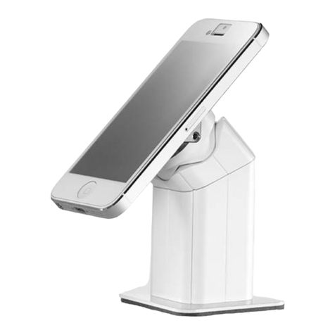
M-TI FREEDOM MICRO II User manual

FREEDOM MICRO®II MECHANICAL MANUAL
1
MTI P/N 063-00410 rev B ©2022 MTI All Rights Reservedwww.MTIGS.com | T:800.426.6844
Product Manual for
FREEDOM MICRO®II Mechanical
DO NOT REMOVE FROM STORE
Contents
1. Components And Accessories 2
2. Baseplate Options 3
3. Speedplate™ Merchandising 5
4. Speedbracket™ Merchandising 7
5. SmartCable™ Merchandising 10
6. RFID Commands 11
7. RFID MTI Connect®Pairing 12
8. LED Status Indicators 13
9. Dimensions 15
10. FCC and ISED Statement 18
For additional support, please reach out to our
Contact Center at 800-426-6844
CONTENTS
WARNING: MTI products contains chemicals known to the State of California to cause cancer and birth defects or other reproductive harm.
Proposition 65, California Health & Safety Code Section 25249.6 et seq. Visit oehha.ca.gov for more information.
FREEDOM MICRO®II MECHANICAL MANUAL
2
MTI P/N 063-00410 rev B ©2022 MTI All Rights Reservedwww.MTIGS.com | T:800.426.6844
COMPONENTS AND ACCESSORIES
SpeedBracket™
Slot MountingThrough Hole MountingVHB Mounting
SpeedPlate™ OptionsFreedom Micro®II Tool
Mounting Options
Freedom Micro®II RiserFreedom Micro®II Puck
Phones
Tablets
FREEDOM MICRO®II MECHANICAL MANUAL
3
MTI P/N 063-00410 rev A ©2022 MTI All Rights Reservedwww.MTIGS.com | T:800.426.6844
1
3
2
4
Attach the baseplate with the included screws. Peel the red lm from the adhesive.
Place Micro position in desired location. Press down on
the base plate for 10 seconds for full adhesive contact.
Allow 24 hours for full adhesion.
BASEPLATE OPTIONS - ADHESIVE
1 2 3
Do not cut power cable.
ADHESIVE POSITION REMOVAL
4
MTI P/N 063-00410 rev B ©2022 MTI All Rights Reservedwww.MTIGS.com | T:800.426.6844
1
3
2
4
MOUNTING SLOT & THROUGH-HOLE ADAPTERS
Slot adapter shown. Through-hole adapter attaches in the same way.
BASEPLATE OPTIONS - SLOT & THROUGH-HOLE ADAPTERS
Place the power cable into the slot on the bottom
plate, then slide it up over the slot adapter post.
Insert the Freedom Micro®II position into the slot or
hole.
Secure the Freedom Micro®II position with the knob.
FREEDOM MICRO®II MECHANICAL MANUAL
5
MTI P/N 063-00410 rev B ©2022 MTI All Rights Reservedwww.MTIGS.com | T:800.426.6844
1
3
2
4
SPEEDPLATE™ MERCHANDISING
Peel red backing off of the adhesive on the
SpeedPlate™.
Clean the device with an alcohol wipe.
Apply the SpeedPlate™ to the phone, with the cable
retainer towards the charge port of the phone. Use the
SpeedPlate™ cable retainer as alignment reference.
Place the device onto the puck and rotate the device
clockwise on the puck until it locks into place.
FREEDOM MICRO®II MECHANICAL MANUAL
6
MTI P/N 063-00410 rev B ©2022 MTI All Rights Reservedwww.MTIGS.com | T:800.426.6844
1
3
2
4Remove the SpeedPlate™ from the Freedom Micro®II
Puck, then release and remove the Freedom Micro®II
tool.
With the Freedom Micro®II tool held in the twisted
position, rotate the SpeedPlate™ counterclockwise.
Twist the Freedom Micro®II tool clockwise 45 degrees
and hold it in place.
Insert the crescent end of the Freedom Micro®II tool
into the opening on the puck
REMOVING SPEEDPLATE™
REMOVING PUCK FROM TETHER
Once the puck is loose, rotate the puck 45 degrees
counterclockwise in relation to the tether. Lift the puck
off of tether connection.
Lift puck out of riser, insert the crescent end of the
Freedom Micro II tool into the opening below the
charge port on the puck. Twist the Freedom Micro II
tool counterclockwise to unlock the puck from the
tether.
1 2
FREEDOM MICRO®II MECHANICAL MANUAL
7
MTI P/N 063-00410 rev B ©2022 MTI All Rights Reservedwww.MTIGS.com | T:800.426.6844
1
3
2
4
SPEEDBRACKET™ MERCHANDISING
Place the phone into the universal bracket.
Extend the bracket arms as far as needed. The bracket
arms move simultaneously in pairs (top & bottom, and
left & right).
Adjust the universal bracket to t the device snugly.
Open the top and bottom bracket arms,
then the side arms, in that order.
1.
2.
2.
1.
Loosen the arm locking security screws on the universal
bracket to loosen the bracket arms.
Some brackets may only have center locking screw
Charge port of phone should face towards
cable clip on SpeedBracket
FREEDOM MICRO®II MECHANICAL MANUAL
8
MTI P/N 063-00410 rev B ©2022 MTI All Rights Reservedwww.MTIGS.com | T:800.426.6844
7 8
65
SPEEDBRACKET™ MERCHANDISING
Tighten center locking security screw on the
SpeedBracket™ to secure the bracket arms in place
around the device. After tightening screws, wiggle the
arms to ensure they have fully engaged the lock teeth.
Place pressure on the top/bottom and the sides to try
and move arms. This is to nd if the arms did not seat
correctly.
Tighten center screw again until tight. Tighten the other
bracket security screw for additional security.
Place device back onto puck.
FREEDOM MICRO®II MECHANICAL MANUAL
9
SPEEDBRACKET™ MERCHANDISING
MTI P/N 063-00410 rev B ©2022 MTI All Rights Reservedwww.MTIGS.com | T:800.426.6844
10
9Rotate the device and bracket clockwise on the puck
until it locks into place.
*click*
Grab the exposed portion of the puck with your thumb
and forenger. Move the phone back and forth to
checking to ensure the bracket locked in place.
*Back and Forth*

Other manuals for FREEDOM MICRO II

3

Other M-TI Security Sensor manuals

M-TI CX FLEX User manual

M-TI

M-TI CX FLEX User manual

M-TI ROGERS FREEDOM MICRO User manual

M-TI

M-TI ROGERS FREEDOM MICRO User manual

Popular Security Sensor manuals by other brands

Elsner 70122 Installation and adjustment

Elsner

Elsner 70122 Installation and adjustment

System Sensor ECO1002 Installation and maintenance instructions

System Sensor

System Sensor ECO1002 Installation and maintenance instructions

THORLABS DET10A2 user guide

THORLABS

THORLABS DET10A2 user guide

Visonic DISC installation instructions

Visonic

Visonic DISC installation instructions

Baumer UNAM 18I6903/S14 quick start guide

Baumer

Baumer UNAM 18I6903/S14 quick start guide

Iget SECURITY M3P17 quick start guide

Iget

Iget SECURITY M3P17 quick start guide

Argus Security A2000L Installation

Argus Security

Argus Security A2000L Installation

Videofied ITR110 installation instructions

Videofied

Videofied ITR110 installation instructions

AVS Electronics WING WS quick guide

AVS Electronics

AVS Electronics WING WS quick guide

Escort SOLO S4 quick reference

Escort

Escort SOLO S4 quick reference

Siemens ADB-11 installation instructions

Siemens

Siemens ADB-11 installation instructions

Baumer UNDK 09G8914/IO quick start guide

Baumer

Baumer UNDK 09G8914/IO quick start guide

TUV BS-660 quick start guide

TUV

TUV BS-660 quick start guide

Guardian Temper Anchor Series instruction manual

Guardian

Guardian Temper Anchor Series instruction manual

RKI Instruments 35-3001A-01 Operator's manual

RKI Instruments

RKI Instruments 35-3001A-01 Operator's manual

3M MACURCO GD-6 User instructions

3M

3M MACURCO GD-6 User instructions

PCB Piezotronics 4115K-10A Installation and operating manual

PCB Piezotronics

PCB Piezotronics 4115K-10A Installation and operating manual

Honeywell krom schroder DG Smart technical information

Honeywell

Honeywell krom schroder DG Smart technical information

manuals.online logo
manuals.online logoBrands
  • About & Mission
  • Contact us
  • Privacy Policy
  • Terms and Conditions

Copyright 2025 Manuals.Online. All Rights Reserved.