SEIKAKU TECHNICAL GROUP RVA200 User manual

RVA200
Volume Control with Audio Out
USER'S MANUAL
AUDIO MATRIX

INDEX
01 SAFETY RELATED SYMBOLS
02 WARNING
03 IMPORTANT SAFETY INSTRUCTIONS
04 FOREWORD
05 AUDIO MATRIX
06 SYSTEM PREVIEW
07 BASIC OPERATION
08 INSTALLATION
09 OPERATION
10 SOFTWARE CONTROL
11 FIRMWARE UPDATE
12 SPECIFICATIONS
1
1
2
3
3
4
7
8
9
10
11
11
AUDIO MATRIX

1
AUDIO MATRIX

2
AUDIO MATRIX

Thanks to purchase the product of our company, please read this manual carefully before
any operation.
Note: This guide contains all the information for the series needed, there might be some
differences between the entity and the description, please refer to the real product for
criterion.
Audio Matrix is a system contains multiple signal inputs and outputs, each input can be
assigned to any output like matrix in mathematic. And there are parameters controls for all
the inputs and outputs, flexible and changeable, all the configuration can be backed up and
restored, easy to copy and to extend. Audio Matrix gives the ability to arrange complex
audio disposition in one device, it provides the opportunity of humanized control for both
professional and beginner.
FOREWORD
AUDIO MATRIX
3
AUDIO MATRIX

SYSTEM PREVIEW
4
Audio Matrix is a system which combines the hardware with software. The core device is
Matrix A8 or Matrix D8. The major features are listed below:
1.12 INPUTS and 12 OUTPUTS
2. In case of extension links, the maximum goes up to 192 inputs and outputs.
3.Broadcast different zones simply by paging unit control.
4.A remote control unit can assign the volume in different zones separately.
5.Control signals are transferred individually with dedicated wires separated from the audio
stream, avoiding conflicts and improving the flexibility and the reliability.
6. The transmission for audio stream is based on AES/EBU protocol, while the control
signal used a RS-485 format.
There are six members in the MATRIX SYSTEM family:
MATRIX A8 --- Server host;
MATRIX D8 --- Server host (Compared to A8, 8 analog I/O for the A8, 8 digital I/O for D8);
RVC1000 --- Remote volume control with a link port;
RVA200 --- Remote volume control with additional outputs;
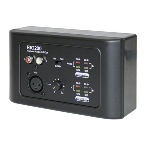
RIO200 --- Remote analog inputs and outputs;
RPM200 --- Remote paging station.
By using a combination of the above six devices, most of the broadcasting or routing
requirements can be fulfilled.
This system fits perfectly for schools, middle and small companies, supermarkets, bars and
restaurants, health clubs, small libraries … The friendly and quick implementation of
primary and advance parameters makes easy the design of professional as well as simple
applications.
Here are some common examples:
AUDIO MATRIX

SYSTEM PREVIEW
5
70/100V Speaker
Office
Stock Room
Fitting Room
RVA200
RETAIL STORE
RPM200
MATRIX A8
MP3/CD Player
Video Plaver
Music Server 70/100V
Sales Floor
Active Speaker
RVC1000
RIO200 RVA200
RPM200
MATRIX A8
MATRIX A8
70/100V
Aerobics
Active
Speakers Active
Speakers
Treadmill Locker Rooms
Locker Rooms
HEALTH CLUB
MP3/CD Player
MP3/CD Player
AUDIO MATRIX

MATRIX A8
Video Projector
Classroom Classroom
RIO200 RIO200
Active
Speakers
Active
Speakers
SCHOOL
SYSTEM PREVIEW
6
RESTAURANT
MP3/CD Player
Restaurant
Bar
Active
Satellite
Terrace
Cloak Room
Toilet
RVA200
RPM200
MATRIX A8
TV
4CH 70/100V
Active
Sub
Video Plaver
AUDIO MATRIX

a. LCD screen
It displays the volume level and the
signal level for a dedicated output.
b. Volume control
Turn the button left or right to adjust
the volume.
Push the button to access to the inputs
and outputs routing function.
c. RD port
Connection to MATRIX-A8. The maximum
CAT 5e cable length is 100 meters.
d. Analog OUT
2 channel analog line Outputs assigned to RD port 9/10 or 11/12 of MATRIX-A8.
RVA200 --Volume Control with Audio Out
The RVA200 has the same functionality as the RVC1000 volume control, but it includes 2
additional analog outputs. The device includes a build in D/A converter processing digital
audio AES3 signals from MATRIX-A8.
BASIC OPERATION
7
AUDIO MATRIX

8
Pass cables through inner wall rear case, insert the cable to the RJ45 port, and insert the
phoenix terminal to dedicated port; then fix panel with crews and clip the decorated frame.
Please check the screen, it should be lit and show “ID … ..” , after ID set, it would indicate
“&****” (**** is to represent a 4bit number.) Note this is under presupposition the other end is
linked with a sever host and be powered on.
INSTALLATION
AUDIO MATRIX

Volume adjustment
Rotate encoder to move cursor on Output* item, push encoder and turn over to select the
channels needed to be adjusted. Click to confirm the output, scroll to adjust. Value shows
on the upper right corner of the screen.
Channel assignment
Scroll encoder to move cursor on In* item,push to enter select interface, check the ones
needed by clicking encoder. After the items checked, shift cursor to “exit” , push to back to
main menu.
OPERATION
9
OUT01
IN09
&1160
AES
OUT01
12.
Exit
IN12
11. IN11
OUT01
IN09
&1160
AES
AUDIO MATRIX

SOFTWARE CONTROL
ID modification
Right click on the “DeviceID” position, the function menu popped up as shown; click
“Change DeviceID” , then enter the number(4 bit) you wanted in the text box, finally click
OK to save and to take effect.
Note: The first time to use the whole system, initial work to assign ID for each device is
necessary for its functioning.
10
Please use high rated network cable to connect the Ethernet port of PC and the LAN port
of serve host device. Then run MatrixSystemEditor, make sure the IP is linked rightly by the
remarks given by dialogs. At the main interface, you can drag the device in the left column
to the right area, it is the operation to add a device. Please make sure the device you added
is physically linked, or there would be no effects even if all settings are saved. Double click
for specific operation, here we add a RVA200.
If the device is connected properly, the gray rectangle in the left middle would turn to green.
Device rename
Double click on the device block, and the click the “CHANGE DEVICE NAME” on the
shown dialog, another window popped up, enter the name you wanted to textbox and click
“Submit” button to save.( Please make sure the name can only consist of alphabets,
numbers and common symbols.)
AUDIO MATRIX

NF05185-1.0
SPECIFICATIONS
For more information about firmware, please visit WWW.SEIKAKU.COM. Please check the
hardware version twice to identify the compatibility of firmware tended to upgrade.
RVA200 --Volume Control with Audio Out
Analog Outputs x 2
• Active Balanced
• Connectors: Euroblock 2 x 3-pin, 5 mm pitch
• Impedance: 240 Ohm
• Maximum Output: +20.0 dBu
• Frequency Response: 20Hz~20KHz,0dB±1.5dB
• Dynamic Range: -107dB max, A weighted
• Crosstalk: -87dB max, A weighted
LCD Display
• Volume range: -∞ - +15dB
Ports
• RD net to Matrix: RJ45, 100 m CAT 5e cable (150 m with ground connection)
Dimensions
• L x H x D: 147 x 86 x 47 mm
FIRMWARE UPDATE
11
AUDIO MATRIX
This manual suits for next models
1
Table of contents
Other SEIKAKU TECHNICAL GROUP Network Router manuals
Popular Network Router manuals by other brands
Fritz!
Fritz! FRITZ!Box 4020 Configuration and operation

ZyXEL Communications
ZyXEL Communications PRESTIGE 335 user guide
ZyXEL Communications
ZyXEL Communications P-2812HNU-51c user guide
UHP NETWORKS
UHP NETWORKS UHP-200 installation guide
D-Link
D-Link DWR-961 user manual
Grandstream Networks
Grandstream Networks GWN7000 user guide
