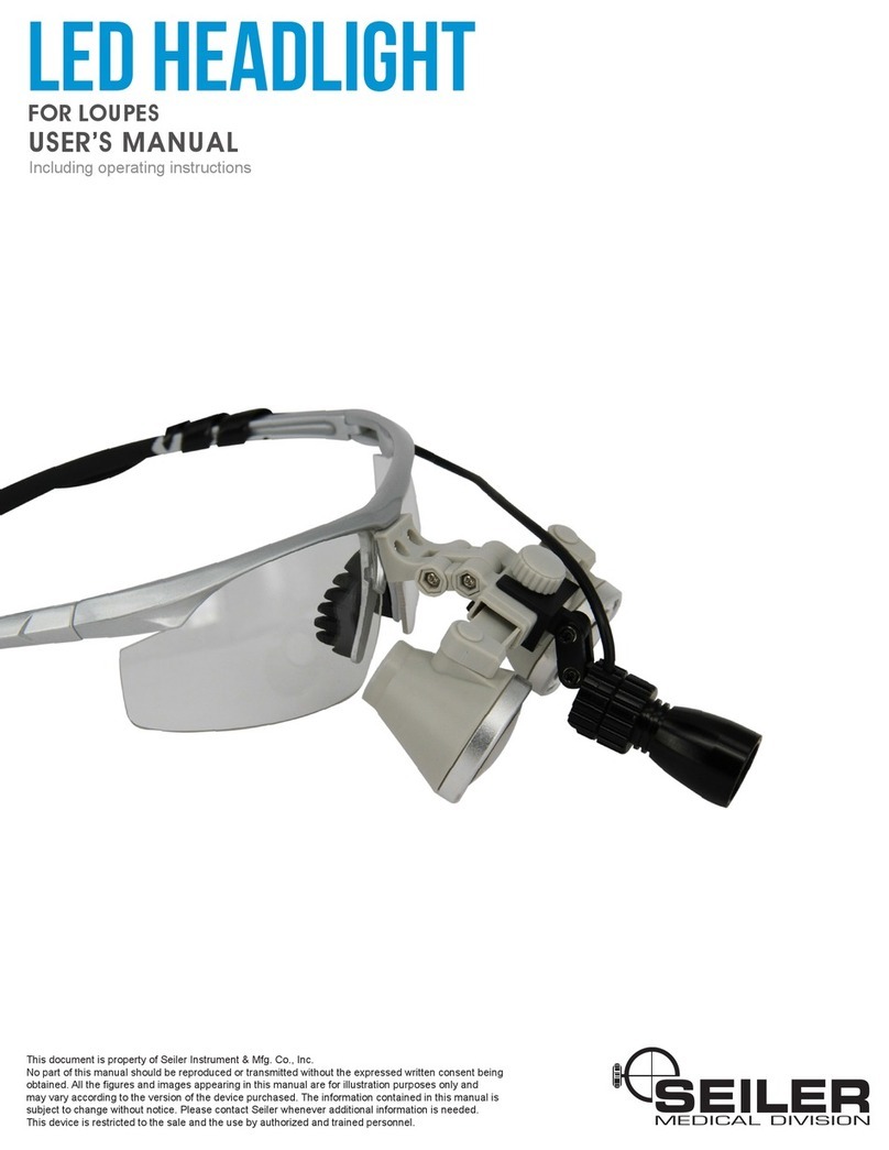
Seiler P1181 User manual

Operation Manual
Model P1181
LED Headlight
Manual

Owner’s Record
Model Number
Serial Number
Date Purchased
Location Purchased


Contents
Symbols 2
Warnings 3
Description 4
Set Up 5
Operation 6
Maintenance 8
Specification 9
Package Contents 10
Warranty 11
Product Support 12
1

Symbols
NOTE:
This symbol cautions that surfaces may be hot
and could be a burn hazard.
This term contains critical information regarding
safe handling and use of this system. Device
malfunction or property damage could result if
these instructions are not followed.
This term contains important information
regarding set-up and operation to facilitate ease
of use and obtain effective results.
WARNING:
This term contains critical information by
identifying conditions or practices that may result
in injury or loss of life if these instructions are not
followed.
Symbols Used in this Manual or on the Device
2

Warnings
3
The Li-ION battery
produces significant
amounts of heat if
improperly recharged.
Only attempt to
recharge the unit
using the supplied
battery charger.
Attach to unit before
plugging into the wall.
Hazard Actions To Be Taken/
Prevented
Risk of Fire
The Li-ION
battery may
overheat if
improperly
recharged.
Only attempt to
recharge the battery
using the supplied
battery charger.
Attach to battery
before plugging into
the wall.
Hazard Actions To Be Taken/
Prevented
Burn risk to
personnel.
Warning -This device presents a risk of burn, fire or explosion
The system contains
a Li-ION battery which
can overheat or
explode.
In the event of
overheating or an
explosion the
controller may suffer
internal damage as a
result.
Read the manual in
its entirety and heed
all safety warnings
before operating the
light source.
Only factory
personnel shall
inspect the unit for
internal damage.
Do not attempt to
charge the battery with
a power supply other
than that provided with
the system.
Hazard Actions To Be Taken/
Prevented
Risk of
Explosion

4
Description
The P1181 LED Headlight Illuminator is a high intensity spot
light source for use with surgical eyeglass systems.
The P1181 system consists of a
remote high output LED lamp
assembly integrated into a position
adjustable aluminum carrier. A single
cable supplies the power from the
intensity controller.
The intensity controller uses a
microprocessor to provide 4 levels of
intensity and has an integrated Li-
ION battery and recharge control
circuitry.
Power is supplied using a wall
socket supply. This power supply is
specific to the P1181 system and
must be the only power unit used for
recharging to prevent damage.
Because of the intense brightness of
the LED the user should avoid directly
viewing the LED head light.
Photo above shows
LED Controller with
On/Off button
depressed.
Description

5
Unpack Carefully unpack all components. Inspect all
components for any signs of damage, which
may have occurred during shipping.
If shipping damage is suspected, notify
Seiler Inc or your authorized Seiler
distributor immediately.
Charge the
unit before
initial use.
Plug the charger into the unit before plugging
into wall. Only use the supplied wall charger .
The module is fully charged when the GREEN
LED is no longer illuminated.
Note: The headgear LED will not illuminate
and can not be used during charging.
Install the LED
module onto
the surgical
glasses
Install the LED illuminator onto the surgical
glasses using the integrated mounting clip.
Make sure that the mounting clip bottom hole
slips over the small post on the bottom of the
glasses frame.
Photo shows the
mount clip pinched
between two fingers
to open the jaws.
Setup

6
Setup (cont.)
Adjust beam
angle and set
tilt tension
Adjust the LED beam position by tilting the
LED module. Tension to maintain position
can be adjusted with the small set screw
using the supplied tool by tightening clock-
wise. Use small adjustments to avoid damage
from over tension. Do not back the set screw
out or the unit will become disassembled.
Above photo shows the tilt procedure for the LED
head light assembly.
Above photo shows the tension adjustment for the
LED head light assembly using the supplied tool.

7
Power Up Press the On/Off button to power up the LED
module.
Set Intensity Set the output brightness level by depressing
the intensity button. There are 4 levels of
intensity. The unit will step thru the various
intensity levels as illustrated below. NOTE:
The LED will not illuminate while connected to
the battery charger.
Photo shows LED
Controller with
On/Off button
depressed.
Photo shows LED
Controller with
Intensity button
depressed.
Operation
LOW
MEDIUM
HIGH
MAX
Intensity
sequence

8
LED
Won’t
Power Up
CHECK ............
CHECK ............
CHECK ............
CHECK ............
Recharge battery.
Wires are not damaged.
On/Off switch has been pressed ‘ON’.
LED will not illuminate while charging.
Maintenance
If the unit should malfunction, and this troubleshooting matrix does
not correct the problem, then contact technical assistance.
LED
module
won’t stay
in position
CHECK ............
CHECK ............
Power cable not binding or snagged.
Adjust LED module tension with
supplied tool.
Maintenance

Specifications
Battery Charger
Run time
Charging Time
Power
Consumption
Specifications
100-240 VAC, 50-60Hz, 0.2A@115VAC
8 hours at full charge
4 Hours (Approximate)
2 Watts
Operating Limits Storage Limits
Temperature 10˚to25˚C
(50˚to77˚F)
Relative
Humidity
30% to 75% 0% to 100%
(Non-Condensing)
0˚to+50˚C
(32˚to122˚F)
9

10
Package Contents:
Foam padded carrying case (1 ea)
LED headlight assembly (1 ea)
Charging power supply (1 ea)
Adjustment tool (1 ea)
Package Contents

11
Limited Guarantee / Warranty
Seiler Instruments warrants this product to be free from
defect in material and workmanship for a period of 12
months following original purchase. The warranty excludes
LEDs, cables, and any other items that have been
misused, neglected, damaged, altered, or used in any
manner inconsistent with the instructions in this manual.
Seiler Instruments’s obligations under this warranty are
limited to the repair, replacement, or reimbursement of the
product only, and, in no event, is Seiler Instruments liable
for any consequential or special damages, or costs related
to the transportation, installation, or any other costs related
to a warranted product.
Warranty

12
Product Support
E-Mail: tleise@seilerinst.com;
micro@seilerinst.com
Phone 800-489-2282
314-968-2282
Fax 314-968-6301
Mailing: 3433 Tree Court Industrial Blvd.
St. Louis, MO 63122
Web: www.seilerinst.com
Product Support

3433 Tree Court Industrial Blvd.
St. Louis, MO 63122
Phone: 314-968-2282 Fax:314-968-6301
1-800-489-2282 (toll-free)
Table of contents
Other Seiler Flashlight manuals
