Sel SEL-2414 User manual

Schweitzer Engineering Laboratories, Inc. SEL-2414 Data Sheet
SEL-2414 Transformer Monitor
Complete System for Control and Monitoring
Major Features and Benefits
The SEL-2414 Transformer Monitor provides an exceptional combination of monitoring, control, and communications
in a compact package.
➤Thermal Monitoring and Metering Capabilities. Safeguard transformers from overheating by tracking thermal
conditions. Track the minimum and maximum transformer top oil temperature, hot-spot temperature, and as many
as 10 RTDs or thermocouples. Calculate hot-spot temperature according to the IEEE C57.91-2011 or the
IEC 60076-7:2018 Ed. 2 standards.
➤Load Tap Position and Control Monitoring. Monitor tap position and raise and lower controls and as many as
32 tap positions by using digital inputs in the binary-coded decimal (BCD) or binary format.
➤High Reliability, Rugged Design, and Low Price. Apply the SEL-2414 in harsh physical and electrical environ-
ments. The SEL-2414 withstands vibration, electrical surges, fast transients, extreme operating temperatures from
–40° to +85°C, and meets stringent utility standards. Compare our superior specification compliance, higher reli-
ability, lower price, and worldwide, ten-year warranty to other transformer monitor alternatives.
➤Flexible I/O for Transformer Status, Alarms, and More. Take advantage of input/output options including dig-
ital inputs for status such as oil level and sudden pressure; RTD and thermocouple inputs for measurements such as
ambient, top-oil, and hot-spot temperatures; digital outputs for control and alarms; analog inputs and outputs; and
ac current and voltage inputs. Easily program monitoring and control functions with powerful logic, math, timers,
counters, and edge-trigger functions. These features allow easy integration with new and retrofit transformer mon-
itor applications. Monitor critical substation assets with comprehensive transformer thermal and through-fault
monitoring.

SEL-2414 Data Sheet Schweitzer Engineering Laboratories, Inc.
2
➤Advanced Asset Monitoring. Monitor critical substation assets with comprehensive transformer thermal and
through-fault monitoring. Calculate top oil, hot-spot, insulation aging acceleration factor, and loss of life while
generating hourly and daily data about your transformer. Capture the maximum/minimum values of all trans-
former model quantities. Capture through-fault current data that could lead to increased transformer wear.
➤Critical Reporting and Logging. Store as many as 512 Sequential Events Recorder (SER) reports of digital input
transitions, time-tagged to the nearest millisecond. Analyze SER reports, analog trending, and oscillographic event
reports for rapid commissioning, testing, and post-event diagnostics. Send the SER data to a communications pro-
cessor or computer for system analysis.
➤Communications and Integration. Automate fan bank control with flexible communications options that provide
easy integration with SCADA. Choose from single and dual Ethernet, Modbus® TCP, DNP3 LAN/WAN,
IEC 61850 Ed. 2, Modbus Serial, EIA-232, EIA-485, Telnet, and File Transfer protocols.
➤AC Metering Capabilities. Take advantage of extensive ac metering and monitoring capabilities. Voltage, current,
power, energy, power factor, frequency; demand/peak demand metering; and maximum/minimum metering are
measured and recorded. Values can be used in programmable calculations and triggers within the meter.
➤Simple Commissioning Tools. Make use of a front-panel HMI that provides complete configuration access and
displays settings, measurements, and calculated values. Easily set with ACSELERATOR QuickSet® SEL-5030 Soft-
ware.
Product Summary
The SEL-2414 Transformer Monitor withstands harsh physical and electrical environments and is built and tested to
meet mission-critical IEEE and IEC protective relay standards. Apply the SEL-2414 to satisfy standalone or distributed
monitoring and control of transformers, or choose from the flexible communications options to connect to a substation
distributed SCADA or automation system, or a SCADA master. Communications options include serial, fiber-optic, and
Ethernet connections and ASCII, SEL Fast Message, MIRRORED BITS® communications, Modbus, and DNP3 protocols.
Figure 1 shows the SEL-2414 functionality.
Apply flexible I/O options to meet the many needs of new or retrofit transformer installations. The SEL-2414 includes
four slots for plug-in I/O cards. Use digital inputs (DI) to monitor critical transformer alarms and status points. Use
analog inputs (AI) to measure pressure, oil level, temperatures, tap positions, and process-level signals (e.g., 4–20 mA,
0–1 mA) from transducers. Operate cooling fans, equipment, alarms, or provide indication with relay-contact or solid-
state digital outputs (DO) and analog outputs (AO). Measure ac currents and ac voltage to calculate three-phase power,
demand, energy, save in oscillographic reports, and for automatic control processes.
Figure 1 Transformer Monitor and Control System
SEL-2600 RTD
Transducer
IRIG-B
Up to 10 RTDs or TC (°C)
Up to 12 RTDs Communications
Alarms
DNP3
Alarms (DOs)
Analog Outputs
Currents Voltages
Status
52 = Breaker
M = Cooling Fan Motor
Control
Sensor(s)
with DOs
Sensor(s)
with AOs (mA)
Core & Coil
Transformer
52
M
52
M
52
M
52
M
SEL-2414

Schweitzer Engineering Laboratories, Inc. SEL-2414 Data Sheet
3
I/O (Status and Alarms)
Use digital inputs to monitor critical alarms such as oil levels, pressures, and gas accumulation; they may also be used
for status points such as fans on/off and breakers open/closed, as shown in Figure 2.
Figure 2 Monitoring Inputs and Control Outputs
SEL-2414
Transformer Monitor
Digital Inputs (DIs) Analog Inputs (AIs)
Digital Outputs (DOs) Analog Outputs (AOs)
Sudden Pressure #
Low/High Oil Tank Level
Fan/Pump #1 On On/Off Fan Bank #1
On/Off Fan Bank #2
RTDs or TCs
(Temperature)
Ambient
Top-Oil (3 for 1)
Measured Hot-Spot
Bottom-Oil (3 for 1)
OLTC Low/High Oil Level
OLTC Tap Position
OLTC Remote/Local
Gas Accumulation #
# = Buchholz
SCADA Alarms
Sudden Pressure Alarm #
Low/High Oil Tank Level
Gas Accumulation Alarm #
Top-Oil Alarm
Hot-Spot Alarm
OLTC Oil Differential Alarm
Pressure/Vacuum Alarm
Pressure Relief Alarm
Cooling Alarm
Load Voltage (3 for 1)
Load Current (3 for 1)
OLTC Tank Oil
Sensors
Pressure/Vacuum Switch
Pressure Relief Device
Loss of Auxiliary Power
OLTC Control Mode
Sensors
Other Cooling . . .
OLTC Motor Current
Fan/Pump #2 On
Wire the digital outputs of sensors to the
digital inputs of the transformer monitor.
Wire digital outputs of the transformer monitor to digital inputs of
the SCADA system or to devices that need to be controlled.
Wire RTD/TC/Analog outputs of sensors to the
RTD/TC/Analog inputs of the transformer monitor.
ControlStatus
SCADA and/or Local HMI Communications
On/Off Fan Bank #3
On/Off Fan Bank #4
Fan Motor Running Timer
OLTC Tap Position
Core & Coil =
Key
Fan/Pump Bank =
On-Load Tap Changer =
General Alarm
Tap Position
Top Oil Temperature
Transduced
Quantities
Ambient Oil Temperature
Bottom Oil Temperature
LTC Tank Oil Temperature

SEL-2414 Data Sheet Schweitzer Engineering Laboratories, Inc.
4
Analyze Transformer Sequence-of-Events
Record sequence-of-events related to transformer events or operations with the Sequential Events Recorder (SER)
function. With this function, you can analyze assertions and deassertions of digital inputs and outputs; as many as 512
state changes to the millisecond for as many as 96 different digital points. The function also captures when the device
powers up and a settings change occurs.
Figure 3 Example SER Report
Analyze Transformer Event
Waveforms
Record analog and digital waveforms at 32 samples/cycle for
as many as 64 power system cycles, approximately 1 s. Use
the event report to move the oscillographic data to your PC.
You can plot your event report data with the SEL-5601-2
SYNCHROWAVE® Event Software or with Microsoft Excel.
Event reports contain ac currents, ac voltages, and digital
inputs and outputs. The report automatically adjusts
content to the I/O cards you use. Reports are stored in
nonvolatile memory to protect your data even if power is
lost. Event reports are optimized for recording power
disturbances and relating them to your process.
Set the report to capture either 15 or 64 power system
cycles of data around the trigger event. For a 60 Hz
system, the event report lengths are 0.25 s and 1.07 s. For
a 50 Hz system, the report lengths are 0.30 s and 1.28 s.
Figure 4 Example SYNCHROWAVE Event Waveform Plot
Trend Transformer Temperatures
and Other Analog Inputs
Record measured ambient, transformer top-oil, trans-
former hot-spot and other analog data (measured or cal-
culated) for trending with the Analog Signal Profile
function. This profile (trending) function can track as
many as 32 analog channels. The function records the
magnitude and time of acquisition of each analog chan-
nel. Use the profile report to move trend records to your
PC and quickly plot the data with Microsoft Excel or any
other spreadsheet application.
SEL-2414 Date: 04/03/2005 Time: 07:21:19
DEVICE
# DATE TIME ELEMENT STATE
17 04/03/2005 06:25:51.120 RB01 Deasserted
16 04/03/2005 06:25:51.125 OUT102 Deasserted
15 04/03/2005 06:26:03.049 RB01 Asserted
14 04/03/2005 06:26:03.053 OUT102 Asserted
13 04/03/2005 06:51:17.748 Device Powered Up
12 04/03/2005 06:51:20.361 OUT101 Asserted
11 04/03/2005 06:51:21.366 OUT101 Deasserted
10 04/03/2005 06:54:10.753 Device Settings Changed
9 04/03/2005 06:54:10.762 FAN BANK #2 OFF Asserted
8 04/03/2005 06:54:11.737 OUT101 Deasserted
7 04/03/2005 07:06:01.739 FAN BANK #2 ON Asserted
6 04/03/2005 07:06:02.744 OUT101 Deasserted
5 04/03/2005 07:06:14.993 Device Settings Changed
4 04/03/2005 07:06:15.002 OUT101 Asserted
3 04/03/2005 07:06:15.977 FAN BANK #1 ON Deasserted
2 04/03/2005 07:13:22.947 OUT101 Asserted
1 04/03/2005 07:13:23.951 OUT101 Deasserted
SER Number Element or Condition Element State

Schweitzer Engineering Laboratories, Inc. SEL-2414 Data Sheet
5
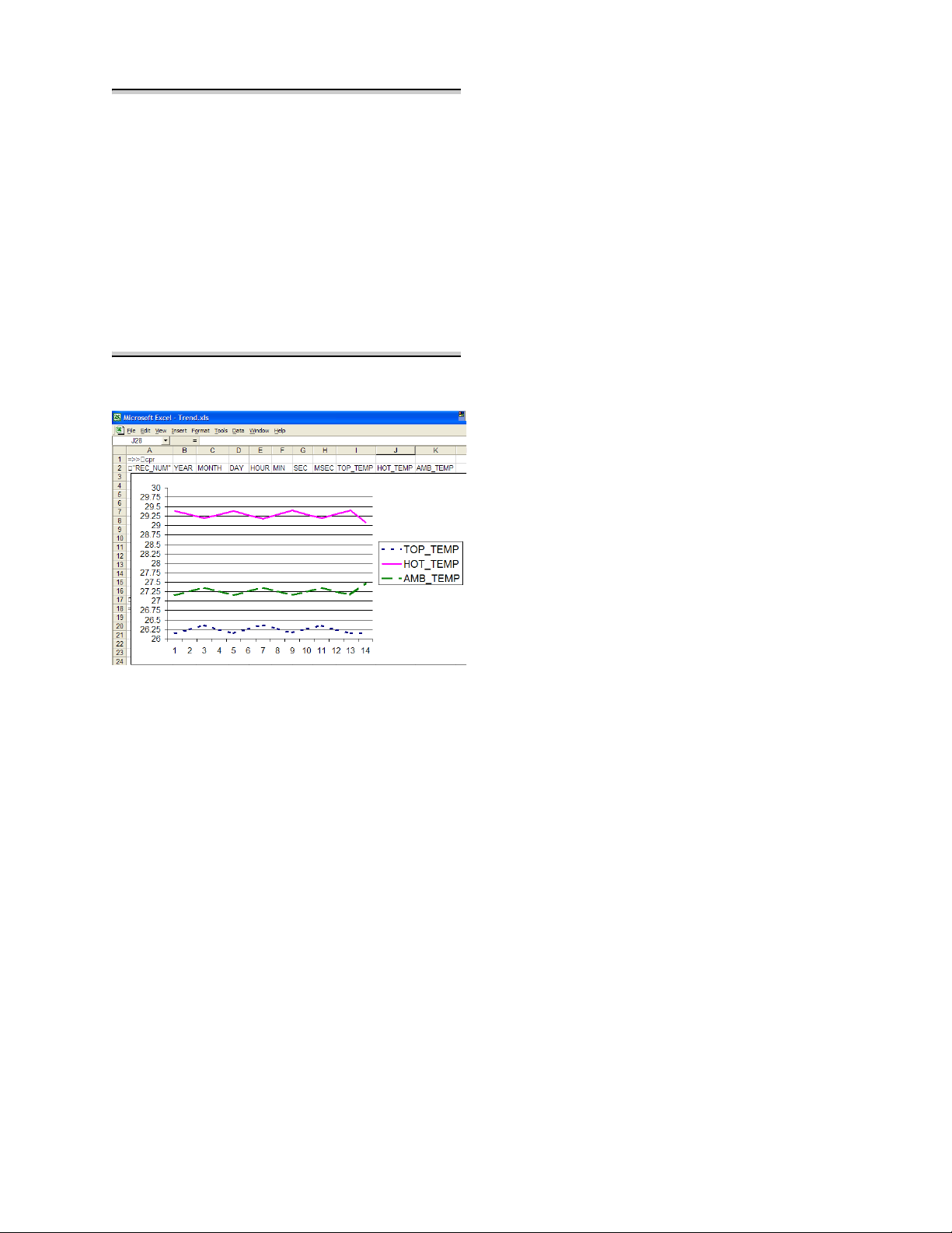
Figure 5 Comma-Separated File Format for Easy
Display, Analysis, and Archiving
Figure 6 Excel Graph of Trend Data
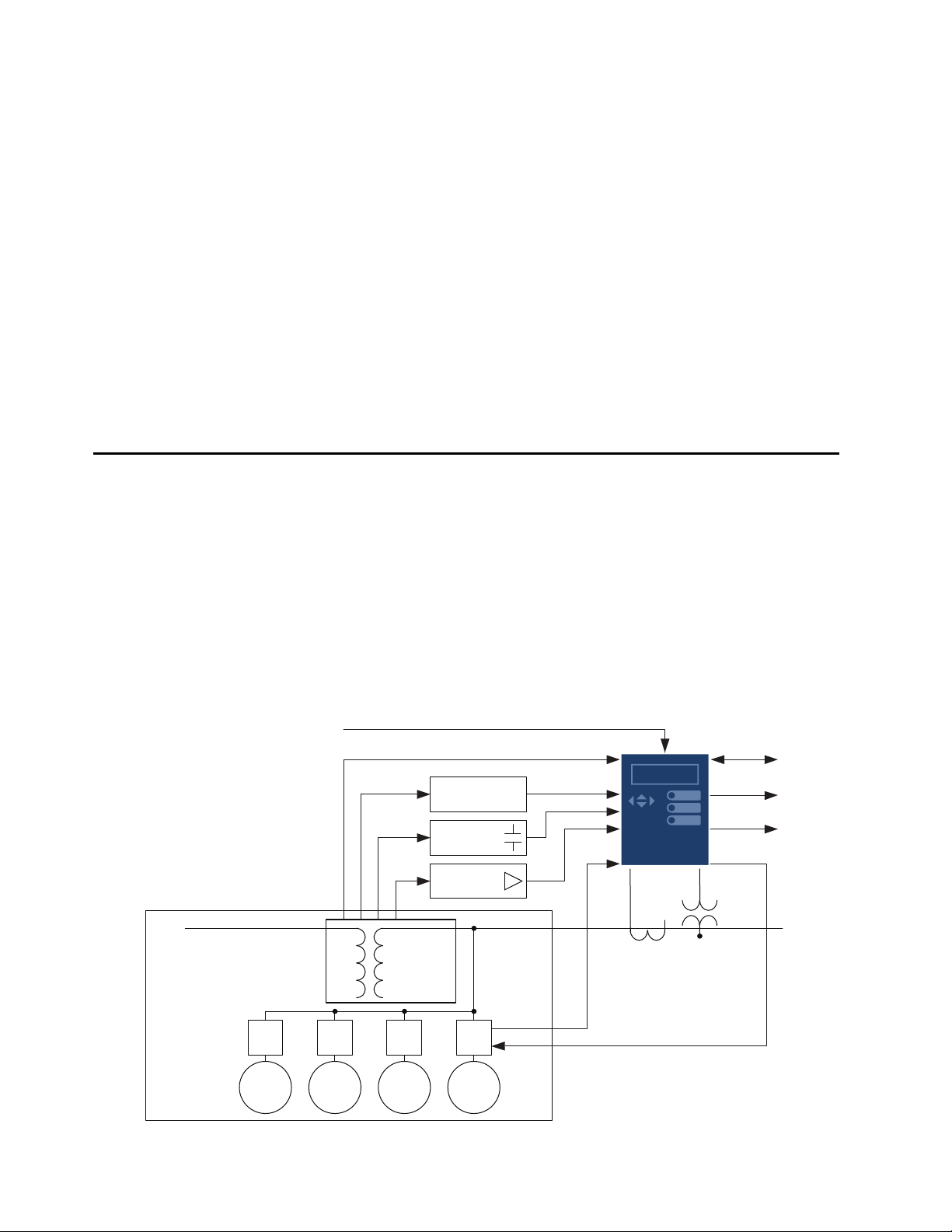
Transformer Thermal Monitoring
Transformer thermal modeling, per IEEE C57.91-2011
or the IEC 60076-7:2018 Ed. 2, is a standard feature in
the SEL-2414. Specify the SEL-2414 to provide this
capability for monitoring and protection of a single
three-phase transformer, a three-phase transformer with
tertiary windings (three-winding mode with separate CT
ratios), or three independent single-phase units. Use the
thermal element to activate a control action or issue a
warning or alarm when your transformer overheats or is
in danger of excessive insulation aging or loss-of-life.
Use the thermal event report to capture current hourly
and daily data about your transformer. Operating
temperature calculations are based on load currents, type
of cooling system, and actual temperature inputs
(ambient and top-oil). Use as many as four thermal
sensor inputs: a single ambient temperature transducer
and one transducer for top-oil temperature from each of
three single-phase transformers. Temperature data are
obtained via an internal RTD/thermocouple card or from
an external SEL-2600A RTD Module. While the
SEL-2414 can receive temperature data at any rate, the
thermal element uses the temperature data once per
minute.
The thermal element operates in one of three modes,
depending upon the presence or lack of measured
temperature inputs: 1) measured ambient and top-oil
temperature inputs, 2) measured ambient temperature
only, and 3) no measured temperature inputs. If the
device receives measured ambient and top-oil
temperatures, the thermal element calculates hot-spot
temperature. When the device receives a measurement of
ambient temperature without top-oil temperature, the
thermal element calculates the top-oil temperature and
hot-spot temperature. In the absence of any measured
ambient or top-oil temperatures, the thermal element
uses a default ambient temperature setting that you select
and calculates the top-oil and hot-spot temperatures. The
device uses hot-spot temperature as a basis for
calculating the insulation aging acceleration factor
(FAA) and loss-of-life quantities. Use the thermal
element to indicate alarm conditions and/or activate
control actions when one or more of the following
exceed settable limits:
➤Top-oil temperature
➤Winding hot-spot temperature
➤Insulation aging acceleration factor (FAA)
➤Daily loss-of-life
➤Total loss-of-life
Generate a thermal monitor report that indicates the
present thermal status of the transformer. Historical
thermal event reports and profile data are stored in the
device in hourly format for the previous 24 hours and in
daily format for the previous 31 days.
The thermal model can be used even if a current card is
not installed. Current magnitude data can be received
through IEC 61850 Ed. 2 or other communications
protocols.
Through-Fault Event Monitor
A through fault is an overcurrent event external to the
differential protection zone. Though a through fault is
not an in-zone event, the currents required to feed this
external fault can cause great stress on the apparatus
inside the differential protection zone. Through-fault cur-
rents can cause transformer winding displacement lead-
ing to mechanical damage and increased transformer
thermal wear because of mechanical stress of insulation
components in the transformer. The SEL-2414 through-
fault event monitor gathers current level, duration, and
date/time for each through fault. The monitor also calcu-
lates a I2t and cumulatively stores these data per-phase.
The SEL-2414 through-fault report also provides percent
of total through-fault accumulated according to the IEEE
Guide for Liquid-Immersed Transformer Through-Fault-
=>>CPR <Enter>
"REC_NUM","YEAR","MONTH","DAY","HOUR","MIN","SEC","MSEC","VA_MAG","VB_M
AG","VC_M
AG","AI301","AI302","AI303","AI304","AI305","AI306","1D7A"
14,2005,9,1,12,10,4,261,2092.127,2099.499,2089.107,-0.001,-0.000,
-0.001,-0.001,-
0.001,-0.001,"1190"
13,2005,9,1,12,15,3,982,2093.966,2099.176,2088.974,-0.001,-0.001,
-0.001,-0.000,-
0.001,-0.001,"11AC"
12,2005,9,1,12,20,4,82,2091.636,2099.117,2089.346,-0.001,-0.000,
-0.001,-0.001,-0
.001,-0.001,"115C"
11,2005,9,1,12,25,4,332,2092.435,2098.398,2088.487,-0.001,-0.001,
-0.001,-0.001,-
0.001,-0.001,"119C"
10,2005,9,1,12,30,4,36,2092.907,2098.208,2089.058,-0.001,-0.001,
-0.000,-0.001,-0
.001,-0.001,"115C"
9,2005,9,1,12,35,4,186,2093.153,2098.865,2089.091,-0.001,-0.000,
-0.001,-0.001,-0
.001,-0.001,"116F"
8,2005,9,1,12,40,3,978,2094.284,2098.926,2089.732,-0.001,-0.001,
-0.001,-0.001,-0
.001,-0.001,"1179"

SEL-2414 Data Sheet Schweitzer Engineering Laboratories, Inc.
6
Current Duration, C57.109-1993. Use through-fault
event data to schedule proactive transformer bank main-
tenance and help justify through-fault mitigation efforts.
Apply the accumulated I2t alarm capability of the device
to indicate excess through-fault current over time.
Load Tap Position and Control
Monitoring
The SEL-2414 supports load tap position and control
(LTPC) monitoring by using digital inputs in the
binary-coded decimal (BCD) or binary format. It can
monitor as many as 32 tap positions with one or three
neutral tap positions. Additionally, it monitors the raise
and lower controls to assert alarms for tap position
change failures or unexpected tap positions.
Implement individual tap position statistics monitoring
with the nonvolatile counters and voltage regulation by
using measured voltages, timers, and analog control
variables.
Simplify Your Transformer
Commissioning
The SEL-2414 front panel simplifies commissioning and
troubleshooting:
➤View field data and calculated values
➤Diagnose data flow problems in seconds instead of
hours
➤Dramatically reduce troubleshooting time
➤Eliminate the need for out-of-service time
Figure 7 Simplify Your Commissioning
Large
temperature
range for
installing in
outdoor
cabinets
Access device
configuration,
detailed I/O status,
alarms, and
measured values
with easy-to-use
controls for
operator interface
Program 4
pushbuttons to
perform direct
user controls
Program LEDs to
indicate control state
Make your own labels by hand or with
included Microsoft® Word template
Configure 7
programmable
LEDs to indicate
I/O activity and
device status
Powered properly and
self-tests are okay
+85°C
—40°C
EIA-232 Port
Ambient Temperature
24.0 deg C
Top Oil Temperature
75.0 deg C
Max Top Oil Temperature
80.1 deg C
LTC Oil Temperature
65.0 deg C
Front-Panel Visualization and Control
Build your own custom displays.
Rotating displays show device measurements and settings
information based on user-configured display points.

Schweitzer Engineering Laboratories, Inc. SEL-2414 Data Sheet
7
Configuration and Commissioning Software
The included ACSELERATOR QuickSet software program simplifies device configuration in addition to providing
commissioning and analysis support for the SEL-2414.
➤Access settings creation help online.
➤Organize settings with the device database manager.
➤Load and retrieve settings using a simple PC com-
munications link.
➤Analyze event records with the integrated wave-
form and harmonic analysis tool.
➤Use the PC interface to remotely retrieve reports
and other system data.
➤Monitor analog data, device I/O, and logic point
status during commissioning tests.
➤Remotely operate and monitor using the device
overview as a virtual front panel.
Settings–Develop Settings Offline With an Intelligent Settings
Editor That Only Allows Valid Settings.
Settings–Create SELOGIC Control Equations With a Drag and
Drop Editor and/or Text Editor.
HMI–Device Overview.

SEL-2414 Data Sheet Schweitzer Engineering Laboratories, Inc.
8
Metering
The SEL-2414 provides extensive metering capabilities. See Specifications for metering and power measurement
accuracies. As shown in Tab le 1, metering includes current and voltage based metering and analog input, math variable,
and remote analog metering. Fundamental, maximum and minimum, and demand metering typically includes phase
voltages and currents; sequence voltages and currents; and power, frequency, and energy.
Additional Ordering Options
The following options can be ordered for any SEL-2414 model:
Ta bl e 1 M e te r in g Ty pe s
Standard
Fundamental IA, IB, IC, VA, VB, VC
Energy Real and Reactive (In and Out)
Maximum and Minimum Frequency, Voltages (VA, VB, VC), Currents (IA, IB, IC, 3I2), Reactive, and Real Power
Demand and Peak Demand IA, IB, IC, IG, 3I2
Analog Input AIx01–AIx08
Math Variable MV01–MV32
Remote Analog RA001–RA128
Analog Signal Profiling
Optional
➤Temperature and thermal (with the external SEL-2600 RTD Module, internal RTD option, or internal RTD/TC option)
➤Maximum and Minimum Temperatures
Digital I/Oa8 DI, 14 DI, 8 DO, 4 DI/4 DO, 4 DI/3 DO with 2 Form C and 1 Form B
Analog I/O 8 AI, 4 AI/4 AO
Temperatures 10 RTDs
CTs and PTs 3 ACI/3 AVI, 4CT, 3 AVI
Port 1 Single/Dual 10/100BASE-T copper (RJ45 connector)
Single/Dual 100BASE FX (LC connector)
Port 2 Fiber-Optic Port (62.5 µm core fiber, ST connectors, SEL-2812 compatible)
Port 4 EIA-232 or EIA-485 (PN 9751)
Protocols Serial: DNP3; Ethernet: Modbus TCP, DNP3 LAN/WAN, FTP, Telnet, IEC 61850
Mounting Surface Mounting kit for in-cabinet installation (PN 915900204)
Environment Conformal coating for chemically harsh and high-moisture environments
aUnless otherwise specified, all digital outputs are Form A.

Schweitzer Engineering Laboratories, Inc. SEL-2414 Data Sheet
9
Automation
Flexible Control Logic and Integration Features
The SEL-2414 is equipped with as many as four inde-
pendently operated serial ports: one EIA-232 port on the
front, one EIA-232 or EIA-485 port on the rear, one
fiber-optic port, and one EIA-232 or EIA-485 port option
card. The device does not require special communica-
tions software. Use any system that emulates a standard
terminal system for engineering access to the device.
Establish communication by connecting computers,
modems, protocol converters, printers, an SEL commu-
nications processor, SCADA serial port, and an RTU for
local or remote communication. Apply an SEL commu-
nications processor as the hub of a star network, with
point-to-point fiber or copper connection between the
hub and the SEL-2414. Included communications proto-
cols are listed below.
Standard Protocols
➤Modbus RTU
➤SEL ASCII
➤SEL Compressed ASCII
➤SEL Fast Meter
➤SEL Fast Operate
➤SEL Fast SER
➤SEL Fast Message
➤SEL MIRRORED BITS
SEL-2414 logic improves integration in the following
ways.
Replaces Traditional Panel Control Switches
Eliminate traditional panel control switches with opera-
tor control pushbuttons or the 32 local bits, available
through the menu system. Program the four conveniently
sized operator pushbuttons to control fan banks and fan
lockout. Set, clear, or pulse local bits with the front-panel
pushbuttons and display. Program the local bits into your
control scheme with SELOGIC control equations. Use the
local bits to perform functions such as breaker trip/close.
Replaces Traditional Indicating Panel Lights
Replace traditional indicating panel lights with 32 pro-
grammable displays. Define custom messages (e.g., Fan
On, Fan Off) to report transformer or device conditions
on the front-panel display. Use advanced SELOGIC con-
trol equations to control which messages the device dis-
plays. Figure 8 shows an example.
Replaces Traditional Temperature Gauges
Replace traditional temperature gauges that show the
temperature, and the maximum and minimum tempera-
ture since last reset. The SEL-2414 Max/Min metering
records and time stamps the maximum and minimum
temperatures and transformer thermal model quantities.
Replaces Traditional Latching Relays
Replace as many as 32 traditional latching relays for
such functions as “remote control enable” with latch bits.
Program latch set and latch reset conditions with
SELOGIC control equations. Set or reset the nonvolatile
latch bits using optoisolated inputs, remote bits, local
bits, or any programmable logic condition. The latch bits
retain their state when the device loses power.
Eliminates External Timers
Eliminate external timers for custom protection or con-
trol schemes with 32 general purpose SELOGIC control
equation timers. Each timer has independent time-delay
pickup and dropout settings. Program each timer input
with any desired element (e.g., time qualify a current ele-
ment). Assign the timer output to control scheme logic.
Eliminates RTU-to-Device Wiring
Eliminate RTU-to-Device wiring with 32 remote bits.
Set, clear, or pulse remote bits using serial port com-
mands. Program the remote bits into your control scheme
with SELOGIC control equations. Use remote bits for
SCADA-type control operations such as trip and close.
Figure 8 Define Custom Messages to Report Station or
Device Conditions
FAN RUNNING
SWITCH OPEN
CONTROL ENABLE
Define custom messages to report
station or device conditions with
user-configured display points.
XFMR OVERLOAD

SEL-2414 Data Sheet Schweitzer Engineering Laboratories, Inc.
10
Communications Architectures
Figure 9 Typical Ethernet and EIA-485 Communications Architectures
Figure 10 Typical EIA-232 and Fiber-Optic Communications Architecture
10/100BASE-T Ethernet Port
- Modbus TCP
- DNP3 LAN/WAN
- Telnet
- FTP
- IEC 61850
Ethernet Switch
DCS or SCADA Master
EIA-485
- Modbus RTU
- DNP3 Level 2 Slave
DCS or SCADA Master
(A) Ethernet Communications Architecture (B) EIA-485 Communications Architecture
SEL-2414 SEL-2414 SEL-2414 SEL-2414 SEL-2414 SEL-2414 SEL-2414 SEL-2414
DCS or SCADA Master
Metallic or Fiber-Optic Serial Cable
Local HMI
SEL RelaySEL Relay
EIA-232 or Fiber Optic
- Modbus RTU
- DNP3 Level 2 Slave
- SEL ASCII
- SEL Fast Message, Fast SER
- SEL Fast Meter, Fast Operate
SEL-2414 SEL-2414
SEL-351SEL-351
SEL-3555

Schweitzer Engineering Laboratories, Inc. SEL-2414 Data Sheet
11
Front- and Rear-Panel Diagrams
Figure 11 Front Panel With Default Configurable Labels
Figure 12 Rear-Panel Connections and Labels
Expansion Slots
Slot C
Slot E
Slot Z
Slot D
Power Supply
2 DI, 3 DO
Ethernet
Fiber-Optic
IRIG-B, EIA-232
8 DI
10 RTD
3 CT/3 PT
8 DO
(A) Rear-Panel Layout (B) Side-Panel Input and Output Designations

SEL-2414 Data Sheet Schweitzer Engineering Laboratories, Inc.
12
Dimensions
Figure 13 SEL-2414 Panel-Mount
Figure 14 SEL-2414 Surface-Mount Dimensions

Schweitzer Engineering Laboratories, Inc. SEL-2414 Data Sheet
13
Specifications
Compliance
Designed and manufactured under an ISO 9001 certified quality
management system
47 CFR 15B, Class A
Note: This equipment has been tested and found to comply with the
limits for a Class A digital device, pursuant to part 15 of the FCC
Rules. These limits are designed to provide reasonable protection
against harmful interference when the equipment is operated in a
commercial environment. This equipment generates, uses, and
can radiate radio frequency energy and, if not installed and used
in accordance with the instruction manual, may cause harmful
interference to radio communications. Operation of this
equipment in a residential area is likely to cause harmful
interference in which case the user will be required to correct the
interference at his own expense.
UL Listed to U.S. and Canadian safety standards (File E220228;
NWGQ2, NWGQ8)
CSA certified for Hazardous Locations to Canadian and U.S.
Standards (File 205948; 2258-02, 2258-82)
CE Mark
RCM Mark
General
Operating Temperature Range
–40° to +85°C (–40° to +185°F), per IEC 60068-2-1 and
60068-2-2.
Note: LCD contrast impaired for temperatures below –20°C and
above +70°C (–4°F and +158°F, respectively).
UL/CSA Conformal
Coated: –40° to +75°C (–40° to +167°F)
Operating Environment
Pollution Degree: 2
Overvoltage Category: II
Relative Humidity: 5–95%, noncondensing
Maximum Altitude: 2000 m
Dimensions
See Figure 13 and Figure 14.
Weight
2.0 kg (4.4 lb)
Frequency
System Frequency: 50, 60 Hz
Inputs
AC Current Input Phase
INOM INOM = 5 A INOM = 1 A
Rated Range: 0.1–96.0 A 0.02–
19.20 A
(according to IEC 60255-5, 60664-1)
Note: This is a linearity specification and is not meant to imply
continuous operation.
Continuous Thermal
Rating: 15 A 3 A
(according to IEC 60255-6,
IEEE C37.90-1989)
1 Second Thermal: 500 A 100 A
(according to IEC 60255-6)
Rated Frequency: 50/60 ±5 Hz 50/60 ±5 Hz
Burden (per phase): < 0.050 VA < 0 .002 VA
Measurement Category: II
AC Current Input Neutral
INOM INOM = 5 A INOM = 1 A
Rated Range: 0.05–10.00 A 0.01–2.00 A
(according to IEC 60255-5, 60664-1)
Note: This is a linearity specification and is not meant to imply
continuous operation.
Continuous Thermal
Rating:
15 A 3 A
(according to IEC 60255-6,
IEEE C37.90-1989)
1 Second Thermal: 500 A 100 A
(according to IEC 60255-6)
Rated Frequency: 50/60 ±5 Hz 50/60 ±5 Hz
Burden (per phase): < 0.1 VA < 0 .01 VA
Measurement Category: II
AC Voltage Input (300 V)
Rated Operating
Vo l t a g e ( U e): 100 –250 Vac
Rated Insulation Voltage: 300 Vac
10-Second Thermal: 600 Vac
Rated Frequency: 50/60 ±5 Hz
Burden: < 0.1 W
DC Transducer (Analog) Inputs
Input Impedance:
Current Mode: 200 Ω
Voltage Mode: >10 kΩ
Input Range (Maximum):
Current Mode: ±20 mA
Voltage Mode: ±10 V
Sampling Rate: At least 5 ms
Step Response: 1 s
Accuracy at 25°C:
ADC: 16 bit
With user calibration: 0.05% of full scale (current mode)
0.025% of full scale (voltage mode)
Without calibration: Better than 0.5% of full scale at 25°C
Accuracy Variation With Temperature:
± 0.015% per °C of full scale (± 20 mA or ±10 V)
DC Transducer (Analog) Inputs Extended Range Option
Input Impedance:
Voltage Mode: >10 kΩ
Input Range (Maximum):
Voltage Mode: ±300 V
Sampling Rate: At least 5 ms
Step Response: 1 s
Accuracy at 25°C:
ADC: 16 bit
With user calibration: 0.025% of full scale (voltage mode)
Without calibration: Better than 0.5% of full scale at 25°C
Accuracy Variation With Temperature:
± 0.015% per °C of full scale (±10 V)
CMRR Typical: 65 db at 60 Hz

SEL-2414 Data Sheet Schweitzer Engineering Laboratories, Inc.
14
Optoisolated Control Inputs
When Used With DC Control Signals:
250 V ON for 200–275 Vdc OFF below 150 Vdc
220 V ON for 176–242 Vdc OFF below 132 Vdc
125 V ON for 100–135.5 Vdc OFF below 75 Vdc
110 V ON for 88–121 Vdc OFF below 66 Vdc
48 V ON for 38.4–52.8 Vdc OFF below 28.8 Vdc
24 V ON for 15–30 Vdc OFF for < 5 Vdc
When Used With AC Control Signals:
250 V ON for 170.6–275 Vac OFF below 106 Vac
220 V ON for 150.3–264 Vac OFF below 93.2 Vac
125 V ON for 85–150 Vac OFF below 53 Vac
110 V ON for 75.1–132 Vac OFF below 46.6 Vac
48 V ON for 32.8–60 Vac OFF below 20.3 Vac
24 V ON for 14–27 Vac OFF below 5 Vac
Current Draw at Nominal
DC Voltage: 2–4 mA (Except for 240 V, 8 mA)
Rated Insulation
Voltage:
300 Vac
Rated Impulse
Withstand Voltage
(Uimp): 4000 V
RTD Input Card
Number of Channels: Ten 3-wire RTDs
Input Type:
Supports the following
RTD types on each
independent input.
100 Ω platinum (PT100)
100 Ω nickel (NI100)
120 Ω nickel (NI120)
10 Ω copper (CU10)
Measuring Range: –200° to 850°C (PT100)
–80° to 250°C (Ni100, Ni120)
–200° to 250°C (Cu10)
ADC Resolution: 24 bit
Accuracy:
CU10, PT100, NI100,
NI120:
±1°C typical at 25°C
±2°C worst case
Resolution: 0.1°C
Update Rate: <3 s
CMRR (typical): 100 dBv
Noise Rejection: Up to 1 Vrms 50/60 Hz
Universal Temperature Input Card
Number of Channels: Ten (thermocouples or 3-wire RTDs)
Input Type:
Supports the following
RTD or TC types on
each independent input.
100 Ω platinum (PT100)
100 Ω nickel (NI100)
120 Ω nickel (NI120)
10 Ω copper (CU10)
J, K, T, E
Measuring Range:
RTDs:
PT100: –200° to 850°C
NI100: –80° to 250°C
CU10: –200° to 250°C
0
5
10
15
20
25
30
35
40
45
50
55
0 5 10 15 20 25 30 35 40 45 50 55 60 65 70 75 80 85 90
Number of DIs Asserted
Ambient Temperature (°C)
SEL-2414 Digital Input Derating
24V/48V
110V/125V
24V/48V
110V/125V
220V/250V
Thermocouples (TCs):
J: –200° to 1200°C
K: –200° to 1370°C
T: –200° to 400°C
E: –200° to 950°C
ADC Resolution: 24 bit
Accuracy:
RTDs:
CU10: ±1°C typical at 25°C
PT100, NI100,
NI120, CU10: ±0.1°C typical at 25°C
CU10, PT100,
NI100, NI120: ±2°C worst case
TCs:
J, K, T, E: ±1°C with field calibration
±3°C without field calibration
Resolution: 0.1°C
Update Rate: < 3 s
CMRR (typical): 100 dBv
Noise Rejection: Up to 1 Vrms 50/60 Hz
Isolation
Number of Banks: Two Banks (5 channels each)
Max. Working
Common Mode: 250 Vdc
Cold Junction
Compensation: Automatic
Time-Code Input
Format: Demodulated IRIG-B
On (1) State: Vih ≥2.2 V
Off (0) State: Vil ≤0.8 V
Input Impedance: 2 kΩ
Accuracy: ±3 ms
Time-Code Input (SNTP)
High-Priority Server
Accuracy: ±5 ms
Accuracy: ±25 ms
Outputs
General
OUT103 is Form C Trip Output, all other outputs are Form A.
Dielectric Test Voltage: 2000 Vac
Impulse Withstand
Voltage (Uimp): 4000 V
Mechanical Durability: 10M no load operations
DC Output Ratings
Electromechanical
Rated Operational
Voltage: 250 Vdc
Rated Voltage Range: 19.2–275 Vdc
Rated Insulation Voltage: 300 Vdc
Make: 30 A @ 250 Vdc per IEEE C37.90
Continuous Carry: 6 A @ 70°C; 4 A @ 85°C
Continuous Carry
(UL/CSA Derating with
All Outputs Asserted): 5 A @ < 60°C; 2.5 A 60 to 70°C
Thermal: 50 A for 1 s
Contact Protection: 360 Vdc, 40 J MOV protection across
open contacts

Schweitzer Engineering Laboratories, Inc. SEL-2414 Data Sheet
15
Operating Time (coil
energization to contact
closure, resistive load): Pickup or Dropout time ≤8 ms typical
Breaking Capacity
(10,000 operations) per
IEC 60255-0-20:1974:
24 Vdc 0.75 A L/R = 40 ms
48 Vdc 0.50 A L/R = 40 ms
125 Vdc 0.30 A L/R = 40 ms
250 Vdc 0.20 A L/R = 40 ms
Cyclic Capacity
(2.5 cycles/second) per
IEC 60255-0-20:1974:
24 Vdc 0.75 A L/R = 40 ms
48 Vdc 0.50 A L/R = 40 ms
125 Vdc 0.30 A L/R = 40 ms
250 Vdc 0.20 A L/R = 40 ms
Fast Hybrid (high-speed high current interrupting)
Make: 30 A
Carry: 6 A continuous carry at 70°C
4 A continuous carry at 85°C
1 s Rating: 50 A
MOV Protection
(maximum voltage): 250 Vac/330 Vdc
Pickup Time: < 50 µs, resistive load
Dropout Time: 8 ms, resistive load
Update Rate: 1/8 cycle
Breaking Capacity (10000 operations):
48 Vdc 10.0 A L/R = 40 ms
125 Vdc 10.0 A L/R = 40 ms
250 Vdc 10.0 A L/R = 20 ms
Cyclic Capacity (4 cycles in 1 second, followed by 2 minutes idle
for thermal dissipation):
48 Vdc 10.0 A L/R = 40 ms
125 Vdc 10.0 A L/R = 40 ms
250 Vdc 10.0 A L/R = 20 ms
Note: Per IEC 60255-23:1994, using the simplified method of
assessment.
Note: Make rating per IEEE C37.90-1989.
AC Output Ratings
Electromechanical
Maximum Operational
Voltage (Ue) Rating: 240 Vac
Insulation Voltage (Ui)
Rating (excluding
EN 61010-1): 300 Vac
Utilization Category: AC-15 (control of electromagnetic
loads > 72 VA)
Contact Rating
Designation:
B300 (B = 5 A, 300 = rated insulation
voltage)
Voltage Protection
Across Open Contacts: 270 Vac, 40 J
Rated Operational
Current (Ie):
3A @ 120Vac
1.5 A @ 240 Vac
Conventional Enclosed
Thermal Current (Ithe)
Rating: 5 A
Rated Frequency: 50/60 ±5 Hz
Pickup/Dropout Time: ≤8 ms (coil energization to contact
closure)
Electrical Durability
Make VA Rating: 3600 VA, cosφ = 0.3
Electrical Durability
Break VA Rating: 360 VA, cosφ = 0.3
Fast Hybrid (high-speed high current interrupting)
Make: 30 A
Carry: 6 A continuous carry at 70°C
4 A continuous carry at 85°C
1 s Rating: 50 A
MOV Protection
(maximum voltage): 250 Vac/330 Vdc
Pickup Time: < 50 µs, resistive load
Dropout Time: 8 ms, resistive load
Update Rate: 1/8 cycle
Breaking Capacity (10000 operations):
48 Vac 10.0 A L/R = 40 ms
125 Vac 10.0 A L/R = 40 ms
250 Vac 10.0 A L/R = 20 ms
Cyclic Capacity (4 cycles in 1 second, followed by 2 minutes idle
for thermal dissipation):
48 Vac 10.0 A L/R = 40 ms
125 Vac 10.0 A L/R = 40 ms
250 Vac 10.0 A L/R = 20 ms
Note: Per IEC 60255-23:1994, using the simplified method of
assessment.
Note: Make rating per IEEE C37.90-1989.
Analog Outputs
Current Ranges (Max): ±20 mA
Voltage Ranges (Max): ±10 V
Output Impedance For
Current Outputs: ≥100 kΩ
Output Impedance For
Voltage Outputs: ≤20 Ω
Maximum Load: 0–750 Ω current mode
>2kΩ voltage mode
Accuracy: ±0.55% of full scale at 25°C
Step Response: 100 ms
Communications
Communications Ports
Standard EIA-232 (2 ports)
Location (fixed): Front Panel
Rear Panel
Data Speed: 300–38400 bps
Optional Ethernet port:
Single/Dual 10/100BASE-T copper (RJ45 connector)
Single/Dual 100BASE FX Multimode (LC connector)
Optional multimode fiber-optic serial port:
Class 1 LED product
Complies with IEC 60825-1:1993 + A1:1997 + A2:2001
Fiber-Optic Ports Characteristics
Port 1 (or 1A, 1B) Ethernet
Wavelength: 1300 nm
Optical Connector Type: LC
Fiber Type: Multimode
Link Budget: 16.1 dB
Typical TX Power: –15.7 dBm
RX Min. Sensitivity: –31.8 dBm
Fiber Size: 50–200 µm
Approximate Range: ~6.4 Km
Data Rate: 100 Mb
Typical Fiber
Attenuation: –2 dB/Km
Port 2 Serial
Wavelength: 850 nm
Optical Connector Type: ST
Fiber Type: Multimode
Link Budget: 8 dB
Typical TX Power: –16 dBm
RX Min. Sensitivity: –24 dBm
Fiber Size: 50–200 µm
Approximate Range: ~4 Km with 62.5 µm,
~1 Km with 200 µm
Data Rate: 5 Mb
Typical Fiber
Attenuation: –4 dB/Km

SEL-2414 Data Sheet Schweitzer Engineering Laboratories, Inc.
16
Optional Communications Card
Standard EIA-232 or EIA-485 (ordering option)
Data Speed: 300–38400 bps
Communications Protocols
Modbus RTU slave or Modbus TCP
DNP3 Level 2 Outstation (LAN/WAN and Serial)
IEC 61850 Communications
Ethernet FTP
Telnet
SEL MIRRORED BITS (MBA, MBB, MB8A, MB8B, MBTB)
Ymodem file transfer on the front and rear port
Xmodem file transfer on the front port
SEL ASCII and Compressed ASCII
SEL Fast Meter
SEL Fast Operate
SEL Fast SER
SEL Fast Message unsolicited write
SEL Fast Message read request
SEL Event Messenger Points
Maximum Concurrent Connections
Modbus Slave: 1
DNP3 Level 2 Outstation: 3a
Ethernet FTP: 2
Telnet: 2
a Maximum in any combination of serial and/or LAN/WAN links.
Power Supply
Rated Supply Voltage
Low-Voltage Model: 24/48 Vdc
High-Voltage Model: 110/250 Vdc
110/230 Vac, 50/60 Hz
Input Voltage Range
Low-Voltage Model: 19.2–60 Vdc
High-Voltage Model: 85–275 Vdc
85–264 Vac
Power Consumption
AC: < 40 VA
DC: <15 W
Interruptions
Low-Voltage Model: 10 ms @ 24 Vdc
50 ms @ 48 Vdc
High-Voltage Model: 50 ms @ 125 Vac/Vdc
100 ms @ 250 Vac/Vdc
AC Metering Accuracies
Current
Phase Current: ±0.5% typical, 25°C, 60 Hz, nominal
current
Neutral Current: ±0.5% typical, 25°C, 60 Hz, nominal
current
Negative Sequence (3I2): ±0.5% typical, 25°C, 60 Hz, nominal
current (calculated)
Residual Ground
Current:
±0.5% typical, 25°C, 60 Hz, nominal
current (calculated)
Voltage
Line-to-Neutral Voltage: ±0.08% typical, 25°C, 60 Hz, nominal
voltage
Line-to-Line Voltage: ±0.08% typical, 25°C, 60 Hz, nominal
voltage
Negative-Sequence
(3V2): ±0.5% typical, 25°C, 60 Hz, nominal
voltage (calculated)
Power
Three-Phase Real Power
(kW): ±1% typical, 25°C, 60 Hz, nominal
voltage and current with 0.10 to 1.00
power factor
Three-Phase Reactive
Power (kVAR): ±1% typical, 25°C, 60 Hz, nominal
voltage and current with 0.00 to 0.90
power factor
Three-Phase Apparent
Power (kVA): ±1% typical, 25°C, 60 Hz, nominal
voltage and current
Power Factor
Three-Phase
(wye connected): ±1% typical, 25°C, 60 Hz, nominal
voltage and current (between 0.97
and 1)
Sampling and Processing Specifications
Without Voltage Card or Current Card
Analog Inputs
Sampling Rate: Every 4 ms
Digital Inputs
Sampling Rate: 2 kHz
Contact Outputs
Refresh Rate: 2 kHz
Logic Update: Every 4 ms
Analog Outputs
Refresh Rate: Every 4 ms
New Value: Every 100 ms
Timer Accuracy: ± 0.5% of settings and ±4 ms
With Either Voltage Card, Current Card, or
Both Voltage and Current Cards
Analog Inputs
Sampling Rate: 4 times/cycle
Digital Inputs
Sampling Rate: 32 times/cycle
Contact Outputs
Refresh Rate: 32 times/cycle
Logic Update: 4 times/cycle
Analog Outputs
Refresh Rate: 4 times/cycle
New Value: Every 100 ms
Timer Accuracy: ±0.5% of settings and ±1/4 cycle
Processing Specifications
AC Voltage and
Current Inputs: 16 samples per power system cycle
Frequency Tracking
Range: 44–66 Hz
Digital Filtering: Cycle cosine after low-pass analog
filtering. Net filtering (analog plus
digital) rejects dc and all harmonics
greater than the fundamental.
Control Processing: Four times per power system cycle or 4
ms if no current or voltage card
(except for math variables and analog
signals used in logic, which are
processed every 100 ms)

Schweitzer Engineering Laboratories, Inc. SEL-2414 Data Sheet
17
Type Tests
Environmental Tests
IP Code: IEC 60529:2001
IP34
Vibration: IEC 60255-21-1:1988, Class 1
IEC 60255-21-3:1993, Class 2
IEC 60255-21-2:1988, Class 1
Cold: IEC 60068-2-1:2007
–40°C, 16 hours
Damp Heat, Cyclic: IEC 60068-2-30:2005
25–55°C, 6 cycles,
95% relative humidity
Dry Heat: IEC 60068-2-2:2007
85°C, 16 hours
Dielectric Strength and Impulse Tests
Dielectric Strength: IEC 60255-5:2000
IEEE C37.90-2005
2.0 kVac on ac current and voltage
inputs, analog inputs, contact I/O
2.83 kVdc on power supply and
analog outputs
Impulse: IEC 60255-5:2000
0.5 J, 5.0 kV
RFI and Interference Tests
EMC Immunity
Electrostatic Discharge
Immunity: IEC 60255-22-2:2008
IEC 61000-4-2:2008
Severity Level 4
8 kV contact discharge
15 kV air discharge
Radiated RF Immunity: IEC 60255-22-3:2007
IEC 61000-4-3:2010
10 V/m
IEEE C37.90.2-2004, 35 V/m
Fast Transient, Burst
Immunity: IEC 60255-22-4:2008
IEC 61000-4-4:2011
4 kV @ 5 kHz
2 kV @ 5 kHz for comm. ports
Surge Immunity: IEC 60255-22-5:2008
IEC 61000-4-5:2005
2 kV line-to-line
4 kV line-to-earth
Surge Withstand
Capability Immunity: IEC 60255-22-1:2007
2.5 kV common-mode
1.0 kV differential-mode
IEEE C37.90.1-2002,
2.5 kV oscillatory, 4 kV fast transient
Conducted RF Immunity: IEC 60255-22-6:2001, 10 Vrms
IEC 61000-4-6:2006, 10 Vrms
Magnetic Field
Immunity: IEC 61000-4-8:2009
1000 A/m for 3 seconds
100 A/m for 1 minute
EMC Emissions
Conducted Emissions: IEC 60255-25:2000, Class A
Radiated Emissions: IEC 60255-25:2000, Class A

SEL-2414 Data Sheet Schweitzer Engineering Laboratories, Inc.
18
Technical Support
We appreciate your interest in SEL products and services. If you have questions or comments, please contact us at:
Schweitzer Engineering Laboratories, Inc.
2350 NE Hopkins Court
Pullman, WA 99163-5603 U.S.A.
Tel: +1.509.338.3838
Fax: +1.509.332.7990
Internet: selinc.com/support
Email: [email protected]

Schweitzer Engineering Laboratories, Inc. SEL-2414 Data Sheet
19
Notes

20
© 2008–2021 by Schweitzer Engineering Laboratories, Inc. All rights reserved.
All brand or product names appearing in this document are the trademark or registered trade-
mark of their respective holders. No SEL trademarks may be used without written permission.
SEL products appearing in this document may be covered by U.S. and Foreign patents.
Schweitzer Engineering Laboratories, Inc. reserves all rights and benefits afforded under fed-
eral and international copyright and patent laws in its products, including without limitation
software, firmware, and documentation.
The information in this document is provided for informational use only and is subject to
change without notice. Schweitzer Engineering Laboratories, Inc. has approved only the
English language document.
This product is covered by the standard SEL 10-year warranty. For warranty details, visit
selinc.com or contact your customer service representative. *PDS2414-01*
2350 NE Hopkins Court • Pullman, WA 99163-5603 U.S.A.
Tel: +1.509.332.1890 • Fax: +1.509.332.7990
selinc.com • inf[email protected]
SEL-2414 Data Sheet Date Code 20210723
Table of contents
Other Sel Monitor manuals