SelectLine Video 8 User manual

Economy functional & digital audio access systems
Video 8 & 16
Functional
Installation Manual
07/06/2002
S
electLine
S
electine
Select Manufacturing Limited
Unit H1 - The Seedbed Centre - Wyncolls Road - Severalls Business Park - Colchester - Essex CO4 9HT
Telephone +44(0)1206 855800 - Facsimile +44(0)1206 855801
Functional Video
Functional Video
Revision 1.08 Date: 10/03/2009

Contents
Page
VIDEO FUNCTIONAL SYSTEMS:
System Overview
System Controller Overview
System Wiring Overview
Request To Exit (Momentary) Wiring Detail
Request To Exit (Timed) Wiring Detail
External Trades Clock Wiring Detail
5
6
7
8
Single Entrance Panel Wiring Detail
Dual Entrance Panel Wiring Detail
Amplifier Wiring Detail
Dual Panel Display Wiring Detail
12Vdc Auxiliary Output Wiring Detail
Video Monitor wiring Detail
Video Distributor wiring Detail
Panel Camera wiring Detail
Strobe and Sounder Wiring Detail
Emergency Override Switch Wiring Detail
DC Fail Secure Door Release Wiring Detail
DC Fail Safe Door Release Wiring Detail
AC Fail Secure Door Release Wiring Detail
PAC Proximity Access Wiring Detail
Single and Dual Entrance Panels
Amplifier, Dual Panel Display and Auxiliary Output
Video Monitor, Video Distributor and Camera wiring detail
Strobe, Sounder and Emergency Override Switch
AC, DC Door Release and PAC Access Control
Request to Exit and External Trades Clock
11
12-13
14
9
10
Functional Video
Revision 1.8 Date: 10/03/2009
Functional Video
Installation Manual

Contents Page
URMET Amplifier
PC Link Power and Battery
URMET Amplifier Wiring Detail
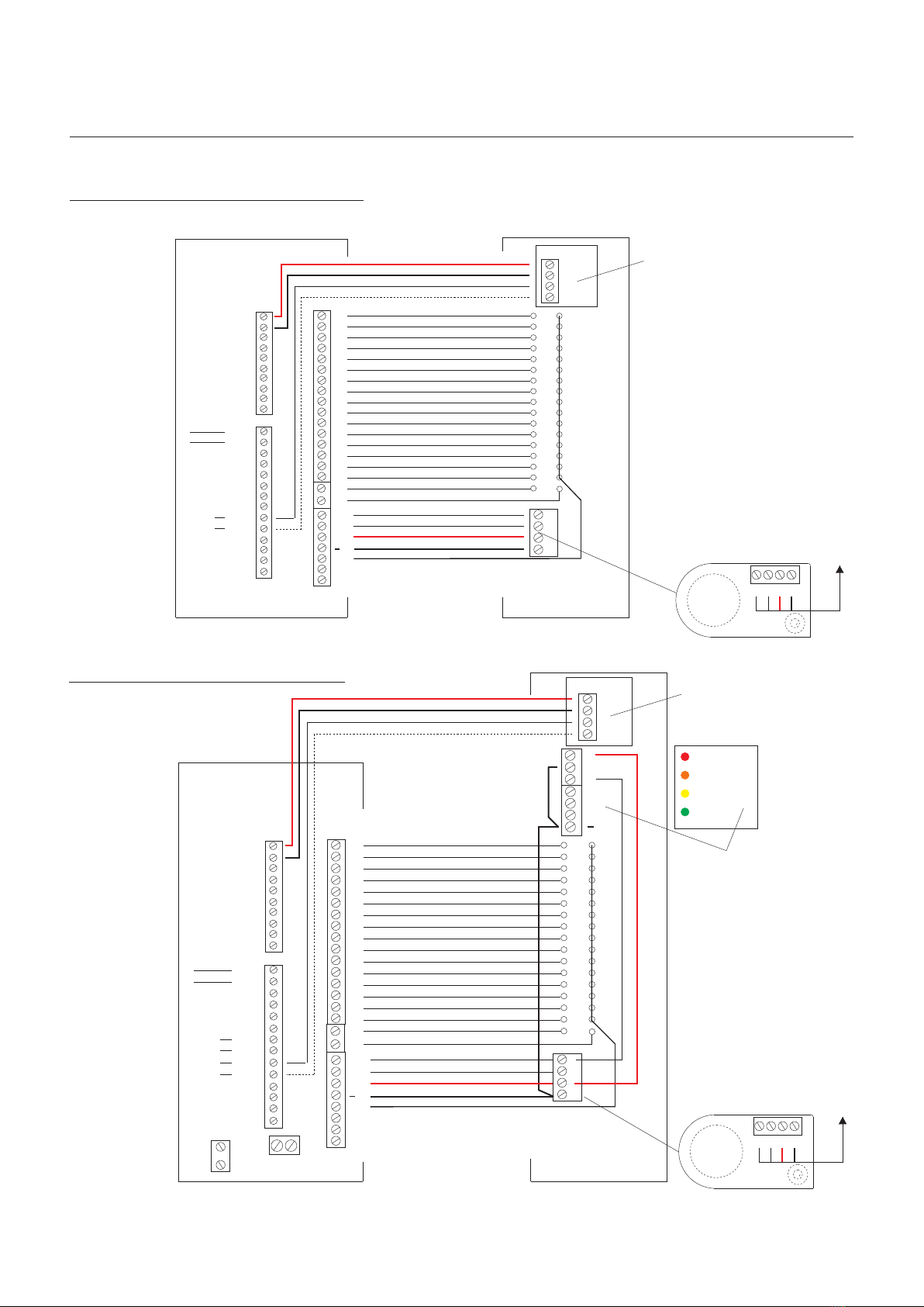
Controller to Single Entrance Panel
Controller to Entrance Panel Amplifier
Controller to Dual and Landing Entrance Panel
Controller to Video Monitor
Video Monitor to Strobe/Sounder
Controller to Door Release Monitor Contacts
Systems to Door Release (ac and dc)
Controller to Emergency Override Switch
Controller to Request To Exit Button
PC Link Wiring Detail
Power Connection Wiring Detail
Battery Connection Wiring Detail
System Controller Summary
System Default Settings
Programming Instructions
Example System Settings
GMT/BSTTime Clock
Digital Time Clock
System Wiring Colour Codes
System Power Specification
User Video Monitor Instruction Leaflet Type: AM-1202/PID
Commissioning/Final Inspection Test Sheet
16
15
29
30
22
23
24-27
28
23
20-22
17-18
19
Functional Video
Installation Manual
Functional Video
Revision 1.8 Date: 10/03/2009

Functional
Video
Systems
- 2 -
Functional Video
Installation Manual
Functional Video
Revision 1.8 Date: 10/03/2009
- 3 -
Functional Video
Installation Manual
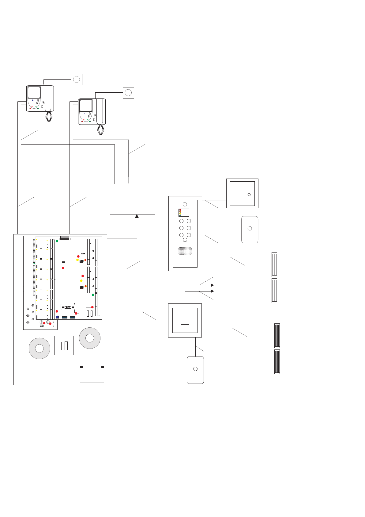
Functional Video System Overview with a PAC Reader Rear Entrance
A - Single Earth
B - 2 Wire (1 Pair)
C - 2 Wire (1 Pair)
D - 8 Wire ( 4 Pair)
M -12 Wire (6 Pair)
J - COAX Cable
2.5mm Mains Type Cable (Continuity)
1mm Mains Type Cable (Lock Power)
CW1308 0.5mm dia Multipair Cable (Minimum)
CW1308 0.5mm dia Multipair Cable (Minimum)
Cw1308 0.5mm dia Multipair Cable (Minimum)
CW1308 0.5mm dia Multipair Cable (Minimum)(PAC Reader) Cable up to 100 Metres
Rg59 75 Ohm Coax Cable
A - Single Earth
B - 2 Wire (1 Pair)
C - 2 Wire (1 Pair)
D - 8 Wire ( 4 Pair)
F - 30 Wire (15 Pair)
A+B
Rear Entrance Reader
Magnetic Locks
with Door Contact
B+C
PUSH
TO EXIT
A+B+C
Fused Spur
Video System Controller
Optional
Battery
A+B+F+J
M
J
J
M
Monitor
Strobe/Sounder
C
DOOR
OPEN
PRIVACY
ON
PRIVACY
S
elect ine
Monitor
Strobe/Sounder
C
DOOR
OPEN
PRIVACY
ON
PRIVACY
S
elect ine
4, 8, 12 &16 way
Video
Distribution
Box
A+D+J
Front Entrance Panel
TRADESTRADES
1,C
2
6
9
PS
PL
DL
1,C
2
6
9
PS
PL
DL
1,C
2
6
9
PS
PL
DL
1,C
2
6
9
PS
PL
DL
1,C
2
6
9
PS
PL
DL
1,C
2
6
9
PS
PL
DL
1,C
2
6
9
PS
PL
DL
1,C
2
6
9
PS
PL
DL
1,C
2
6
9
PS
PL
DL
1,C
2
6
9
PS
PL
DL
1,C
2
6
9
PS
PL
DL
1,C
2
6
9
PS
PL
DL
1,C
2
6
9
PS
PL
DL
1,C
2
6
9
PS
PL
DL
1,C
2
6
9
PS
PL
DL ENTER
Data Enter
Button
& Indicator
FUNCTION
Function Switch Data Switch
Digital Time Clock
DATA
LINE 2
LINE 1
LINE 4
LINE 5
LINE 6
LINE 7
LINE 8
LINE 9
LINE 10
LINE 11
LINE 12
LINE 13
LINE 14
LINE 15
LINE 16
1,C
2
6
9
PS
PL
DL
LINE 3
RESET
System Reset
Button
5 Amp Fuses
System Supply
Indicator
Auxilliary Supply
Indicator
0V
0V
0V
MFL+
VC2
Mains Fail
MFL-
12V
12V
12V
B+
B
TC+
TC-
ON
1 2 3 4 5 6 7 8
ON
1 2 3 4 5 6 7 8
PANEL 1
3
4
5
6
7
8
9
10
11
12
13
14
15
16
1
2
1
CC
DML
SBL
LS+
FCL
LS1
LS2
SA
SE
LC
LS -
2
+
RTE/T
RTE/T
RTE/T
RTE/T
DMS
DMS
DMS
DMS
PAC1+
PAC1 -
0
PANEL 2
3
4
5
6
7
8
9
10
11
12
13
14
15
16
1
2
1
CC
DML
SBL
LS+
FCL
LS1
LS2
SA
SE
LC
LS-
2
+
PAC2+
PAC2 -
TR
TR
0
8
12V
12V
0V
0V
9
16
R2
R1
R2
R1
R2
R1
R2
R1
R2
R1
R2
R1
R2
R1
R2
R1
R2
R1
R2
R1
R2
R1
R2
R1
R2
R1
R2
R1
R2
R1
R2
R1
Distribution
-+
Cam1P
CamDP1
CamDP2
CamR
VOUT
Cam2P
12 3
12 3
12 3
12 3
VC1
Functional Video
Revision 1.8 Date: 10/03/2009
D
To PAC Controller
D
A+B
Emergency
Override
Emergency
Override
A+B+C
PUSH
TO EXIT
Magnetic Locks
with Door Contact
B+C
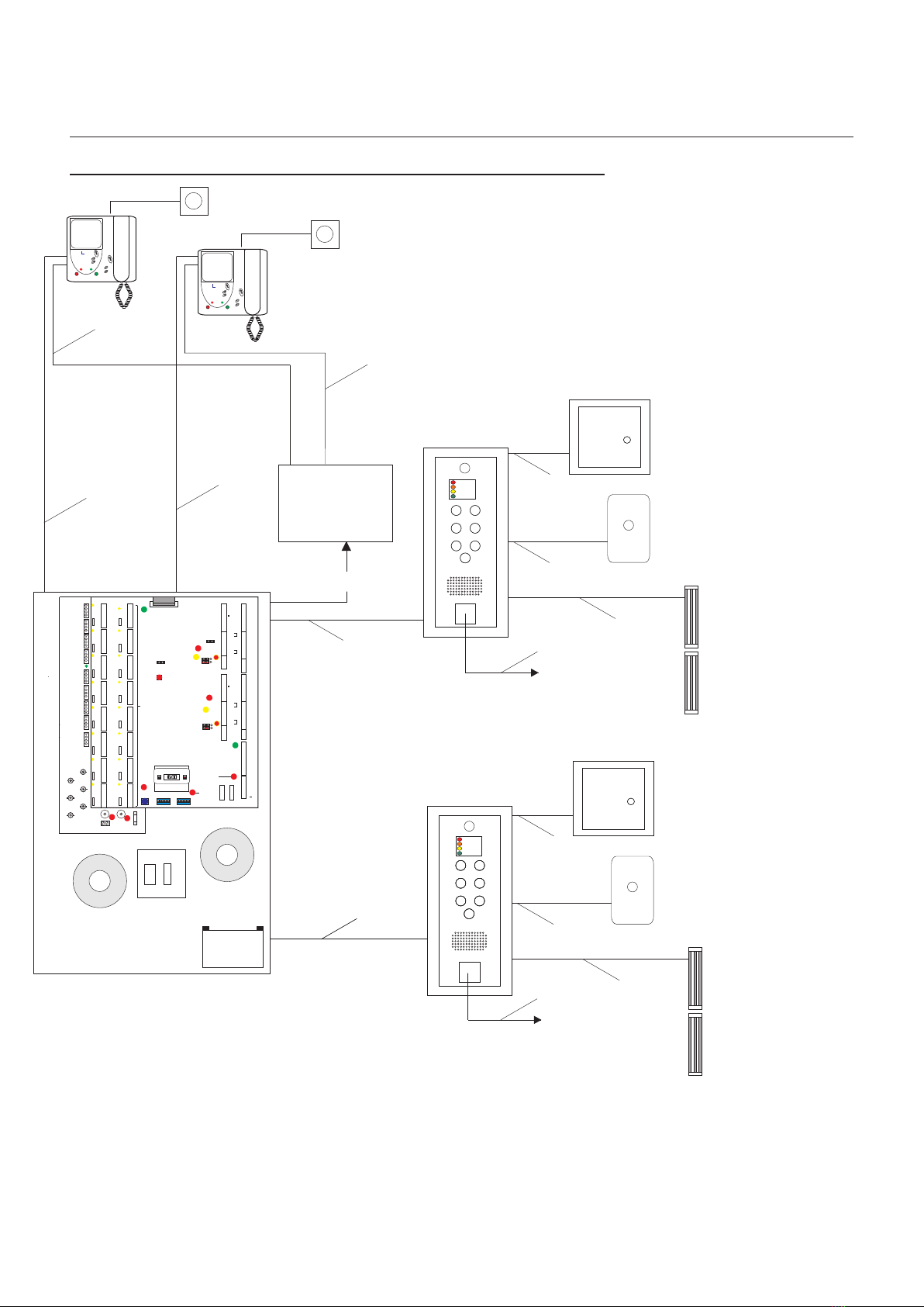
Functional Video System with Two Entrances with PAC Overview
- 4 -
A - Single Earth
B - 2 Wire (1 Pair)
C - 2 Wire (1 Pair)
D - 8 Wire ( 4 Pair)
F - 30 Wire (15 Pair)
2.5mm Mains Type Cable (Continuity)
1mm Mains Type Cable (Lock Power)
CW1308 0.5mm dia Multipair Cable (Minimum)
CW1308 0.5mm dia Multipair Cable (Minimum)
CW1308 0.5mm dia Multipair Cable (Minimum)
CW1308 0.5mm dia Multipair Cable
RG59 Coax Cable
A - Single Earth
B - 2 Wire (1 Pair)
C - 2 Wire (1 Pair)
D - 8 Wire ( 4 Pair)
M -12 Wire (6 Pair)
J - Coax Cable
To PAC Controller
Fused Spur
System Controller
Optional
Battery
A+B+F+J
Rear Entrance Panel
D
Functional Video
Installation Manual
TRADESTRADESTRADESTRADES
A+B+F+J
M
J
J
M
Monitor
Strobe/Sounder
C
DOOR
OPEN
PRIVACY
ON
PRIVACY
S
elect ine
Monitor
Strobe/Sounder
C
DOOR
OPEN
PRIVACY
ON
PRIVACY
S
elect ine
4, 8, 12 &16 way
Video
Distribution
Box
A+D+J
Front Entrance Panel
D
TRADESTRADES
1,C
2
6
9
PS
PL
DL
1,C
2
6
9
PS
PL
DL
1,C
2
6
9
PS
PL
DL
1,C
2
6
9
PS
PL
DL
1,C
2
6
9
PS
PL
DL
1,C
2
6
9
PS
PL
DL
1,C
2
6
9
PS
PL
DL
1,C
2
6
9
PS
PL
DL
1,C
2
6
9
PS
PL
DL
1,C
2
6
9
PS
PL
DL
1,C
2
6
9
PS
PL
DL
1,C
2
6
9
PS
PL
DL
1,C
2
6
9
PS
PL
DL
1,C
2
6
9
PS
PL
DL
1,C
2
6
9
PS
PL
DL ENTER
Data Enter
Button
& Indicator
FUNCTION
Function Switch Data Switch
Digital Time Clock
DATA
LINE 2
LINE 1
LINE 4
LINE 5
LINE 6
LINE 7
LINE 8
LINE 9
LINE 10
LINE 11
LINE 12
LINE 13
LINE 14
LINE 15
LINE 16
1,C
2
6
9
PS
PL
DL
LINE 3
RESET
System Reset
Button
5 Amp Fuses
System Supply
Indicator
Auxilliary Supply
Indicator
0V
0V
0V
MFL+
VC2
Mains Fail
MFL-
12V
12V
12V
B+
B
TC+
TC-
ON
1 2 3 4 5 6 7 8
ON
1 2 3 4 5 6 7 8
PANEL 1
3
4
5
6
7
8
9
10
11
12
13
14
15
16
1
2
1
CC
DML
SBL
LS+
FCL
LS1
LS2
SA
SE
LC
LS -
2
+
RTE/T
RTE/T
RTE/T
RTE/T
DMS
DMS
DMS
DMS
PAC1+
PAC1 -
0
PANEL 2
3
4
5
6
7
8
9
10
11
12
13
14
15
16
1
2
1
CC
DML
SBL
LS+
FCL
LS1
LS2
SA
SE
LC
LS-
2
+
PAC2+
PAC2 -
TR
TR
0
8
12V
12V
0V
0V
9
16
R2
R1
R2
R1
R2
R1
R2
R1
R2
R1
R2
R1
R2
R1
R2
R1
R2
R1
R2
R1
R2
R1
R2
R1
R2
R1
R2
R1
R2
R1
R2
R1
Distribution
-+
Cam1P
CamDP1
CamDP2
CamR
VOUT
Cam2P
12 3
12 3
12 3
12 3
VC1
Video System Controller
Functional Video
Revision 1.8 Date: 10/03/2009
A+B
Emergency
Override
Emergency
Override
A+B+C
PUSH
TO EXIT
Magnetic Locks
with Door Contact
B+C
A+B
Emergency
Override
Emergency
Override
A+B+C
PUSH
TO EXIT
Magnetic Locks
with Door Contact
B+C

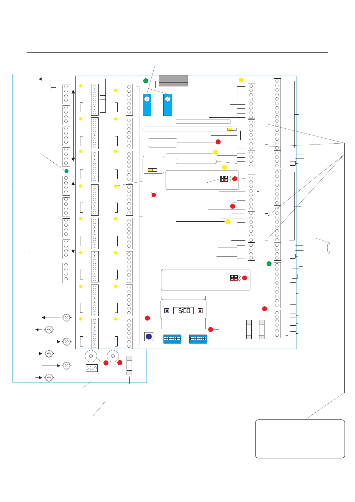
Functional System Controller Overview
- 5 -
Functional System Controller Overview
Functional Video
Installation Manual
Note:
Fitted Links will give a
12VDC Lock output. With the Links
removed a seperate 12VDC/AC
-24VDC/AC Lock Power Supply can
be connected to LS1(+) and LS2 ( - )
5 Amp Fuse
Panel 1 Busy
Panel 2 Busy
18Vdc Supply Indicator
12Vdc Supply Indicator
R2 1
8
R1
R2
R1
R2
R1
R2
R1
R2
R1
R2
R1
R2
R1
R2
R1
R2
R1
R2
R1
Sbl1
Sbl2
R2
R1
R2
R1
R2
R1
R2
R1
R2
R1
R2
R1
+
+
+
+
-
-
-
-
-
+
Camera Supply x 5
+ 18Vdc Monitor Supply
0V Monitor Supply
9
16
1
5
Vout
Scn
CamR
CamDP
Cam2P
Cam1P
Scn
Scn
Scn
Scn
Video Output
Video Output
Digital Riser Output
Digital Riser Output
Digital Panel Input
Digital Panel Input
Lobby Camera2 Input
Lobby Camera1 Input
Lobby Camera2 Input
Lobby Camera1 Input
Panel Camera1 Input
Panel Camera1 Input
Panel Camera2 Input
Panel Camera2 Input
18Vdc
Distributor Supply
Cam1L
Cam2L
Scn
Scn Distribution
-+
Mains Fail Output
to Door LED
3 x 12 VDC Auxilliary
Power Outputs
TX
TX
AC Power Input
from LV Transformer
Secondary Trades
Clock input
Mains Fail Indicator
Backup Battery
Input
Entrance Panel 1
Buttons
PAC Entrance 1 Input
PAC Entrance 1 Input
TR
TR Trades Button
Entrance Panel 2
Buttons
PAC Entrance 2 Input
PAC Entrance 2 Input
TR
TR Trades Button
1,C
2
6
9
PS
PL
DL
1,C
2
6
9
PS
PL
DL
1,C
2
6
9
PS
PL
DL
1,C
2
6
9
PS
PL
DL
1,C
2
6
9
PS
PL
DL
1,C
2
6
9
PS
PL
DL
1,C
2
6
9
PS
PL
DL
1,C
2
6
9
PS
PL
DL
1,C
2
6
9
PS
PL
DL
1,C
2
6
9
PS
PL
DL
1,C
2
6
9
PS
PL
DL
1,C
2
6
9
PS
PL
DL
1,C
2
6
9
PS
PL
DL
1,C
2
6
9
PS
PL
DL
1,C
2
6
9
PS
PL
DL
ENTER
Data Enter
Button
& Indicator
FUNCTION
Function Switch Data Switch
Digital Time Clock
DATA
LINE 2
LINE 1
LINE 4
LINE 5
LINE 6
LINE 7
LINE 8
LINE 9
LINE 10
LINE 11
LINE 12
LINE 13
LINE 14
LINE 15
LINE 16
1,C
2
6
9
PS
PL
DL
LINE 3
RESET
System Reset
Button
16 Apartment Inputs
Flat Called Indicator
Flat Called Indicator
Entrance Panel 1 Amplifier
Entrance Panel 1 Button Common
Entrance Panel 1 Busy & Enter Display
DC Lock Power
Healthy Indicator
Lock Released
Indicator
Call Indicator
Lock Released
Indicator
DC Lock Power
Healthy Indicator
12V DC Lock Release
Output ( N/O & N/C )
Request to Exit ( Timed )
Door Monitoring Switch
Request to Exit ( Timed )
Door Monitoring Switch
Entrance Panel 2 Amplifier
Entrance Panel 2 Button Common
Entrance Panel 2 Busy/Enter Display
12V DC Lock Release
Outputs ( N/O & N/C )
5 Amp Fuses
System Supply
Indicator
Auxilliary Supply
Indicator
0V
0V
0V
MFL+
MF
MFL-
12V
12V
12V
B+
B
TC+
TC-
ON
1 2 3 4 5 6 7 8
ON
1 2 3 4 5 6 7 8
PANEL 1
3
4
5
6
7
8
9
10
11
12
13
14
15
16
1
2
1
CC
DML
SBL
LS+
FCL
LS1
LS2
SA
SE
LC
LS -
2
+
RTE/T
RTE/T
RTE/T
RTE/T
DMS
DMS
DMS
DMS
PAC1+
PAC1 -
0
PANEL 2
3
4
5
6
7
8
9
10
11
12
13
14
15
16
1
2
1
CC
DML
SBL
LS+
FCL
LS1
LS2
SA
SE
LC
LS-
2
+
PAC2+
PAC2 -
0
PAC Jumpers
See page 11
PAC Jumpers
See page 11
Telephone Door open Tone ON/OFF Default OFF
Lock Supply + Input (12V-24VAC/DC
Lock Supply - Input (12V-24VAC/DC
Lock Supply + Input (12V-24VAC/DC
Lock Supply - Input (12V-24VAC/DC
Monitor
Voltage
Monitoring
SML2000-3
SML2021-3
Functional Video
Revision 1.8 Date: 10/03/2009
- 5A -
Functional System Controller OverviewFunctional System Controller Overview
Functional Video
Installation Manual
Camera
Supply
x 2
18VDC
Monitor
Supply
To Video
Monitor
Mains Fail Output
to Door LED
3 x 12 VDC Auxilliary
Power Outputs
TX
TX
AC Power Input
from LV Transformer
Secondary Trades
Clock input
Mains Fail Indicator
Video Control (Pre wired)
Backup Battery
Input
PAC Entrance 2 Input
PAC Entrance 2 Input
TR
TR Trades Button
RESET
System Reset
Button
16 Apartment Inputs
Flat Called Indicator
Flat Called Indicator
Entrance Panel 1 Amplifier
Entrance Panel 1 Button Common
Entrance Panel 1 Busy & Enter Display
DC Lock Power
Healthy Indicator
Lock Released
Indicator
Call Indicator
Lock Released
Indicator
DC Lock Power
Healthy Indicator
12V DC Lock Release Output ( N/O & N/C )
Request to Exit ( Timed )
Request to Exit ( Timed )
Door Monitoring Switch
Entrance Panel 2 Button Common
Entrance Panel 2 Busy/Enter Display
12V DC Lock Release
Outputs ( N/O & N/C )
5 Amp Fuses
System Supply
Indicator
Auxilliary Supply
Indicator
Panel Amplifier Active
Panel Amplifier Active
0V
0V
0V
MFL+
VC2
VC1
MFL-
12V
12V
12V
B+
B
TC+
TC-
FUNCTION
Function Switch Data Switch
DATA
ON
1 2 3 4 5 6 7 8
ON
1 2 3 4 5 6 7 8
PANEL 1
1
CC
DML
SBL
LS+
FCL
LS1
LS2
SA
SE
LC
LS -
2
+
RTE/T
RTE/T
RTE/T
RTE/T
DMS
DMS
DMS
DMS
Entrance Panel 1
Buttons
TR
TR Trades Button
3
4
5
6
7
8
9
10
11
12
13
14
15
16
1
2
PAC1+
PAC1 -
PAC Entrance 1 Input
PAC Entrance 1 Input
0
PANEL 2
1
CC
DML
SBL
LS+
FCL
LS1
LS2
SA
SE
LC
LS-
2
+
PAC2+
PAC2 -
0
Telephone Door Release Tone ON/OFF Default OFF
Lock Supply + Input (12V-24VAC/DC
Lock Supply - Input (12V-24VAC/DC
Lock Supply + Input (12V-24VAC/DC
Lock Supply - Input (12V-24VAC/DC
Entrance Panel 2
Buttons
3
4
5
6
7
8
1
2
9
10
11
12
13
14
15
16
Monitor
Activation
5 Amp Fuse
18VDC
Supply
Indicator
18VDC
Distributor
Supply 12VDC
Camera
Supply
18 - 24VDC
Monitor
Supply
8
12V
12V
0V
0V
9
16
Output To Video
Distributors
Video Output
To Next Controller
Digital Panel
2 Input
Digital Panel
1 Input
Func Panel
Camera1 Input
Functional Panel
Camera 2 Input
1,C
2
6
9
PS
PL
DL
1,C
2
6
9
PS
PL
DL
1,C
2
6
9
PS
PL
DL
1,C
2
6
9
PS
PL
DL
1,C
2
6
9
PS
PL
DL
1,C
2
6
9
PS
PL
DL
1,C
2
6
9
PS
PL
DL
1,C
2
6
9
PS
PL
DL
1,C
2
6
9
PS
PL
DL
1,C
2
6
9
PS
PL
DL
1,C
2
6
9
PS
PL
DL
1,C
2
6
9
PS
PL
DL
1,C
2
6
9
PS
PL
DL
1,C
2
6
9
PS
PL
DL
1,C
2
6
9
PS
PL
DL
LINE 2
LINE 1
LINE 4
LINE 5
LINE 6
LINE 7
LINE 8
LINE 9
LINE 10
LINE 11
LINE 12
LINE 13
LINE 14
LINE 15
LINE 16
1,C
2
6
9
PS
PL
DL
LINE 3
ENTER
Data Enter
Button
& Indicator
R2
R1
R2
R1
R2
R1
R2
R1
R2
R1
R2
R1
R2
R1
R2
R1
R2
R1
R2
R1
R2
R1
R2
R1
R2
R1
R2
R1
R2
R1
R2
R1
Distribution
-+
Note:
Fitted Links will give a
12VDC Lock output. With the Links
removed a seperate 12VDC/AC
-24VDC/AC Lock Power Supply can
be connected to LS1(+) and LS2 ( - )
TIME CLOCK
Cam1P
CamDP1
CamDP2
CamR
VOUT
Cam2P
Doors
Lock Release Tone and
Door Open Tone Adjustment
1 2
1 & 2 ON No PAC connected
2 & 3 ON PAC connected
(RED & BLACK must
BOTH be moved).
12 3
12 3
Entrance Panel 2 Amplifier
12VDC Lock Release from
PAC Controller to be
programmed to 2 seconds
Fail Safe.
Door Open Indicator
12VDC
Supply
Indicator
Progressive
Ring Tone
Default ON
Door Monitoring Switch
PAC Jumpers
1 & 2 ON No PAC connected
2 & 3 ON PAC connected
(RED & BLACK must BOTH be moved).
12 3
12 3
SML2000-4
SML2021-4
Functional Video
Revision 1.8 Date: 10/03/2009
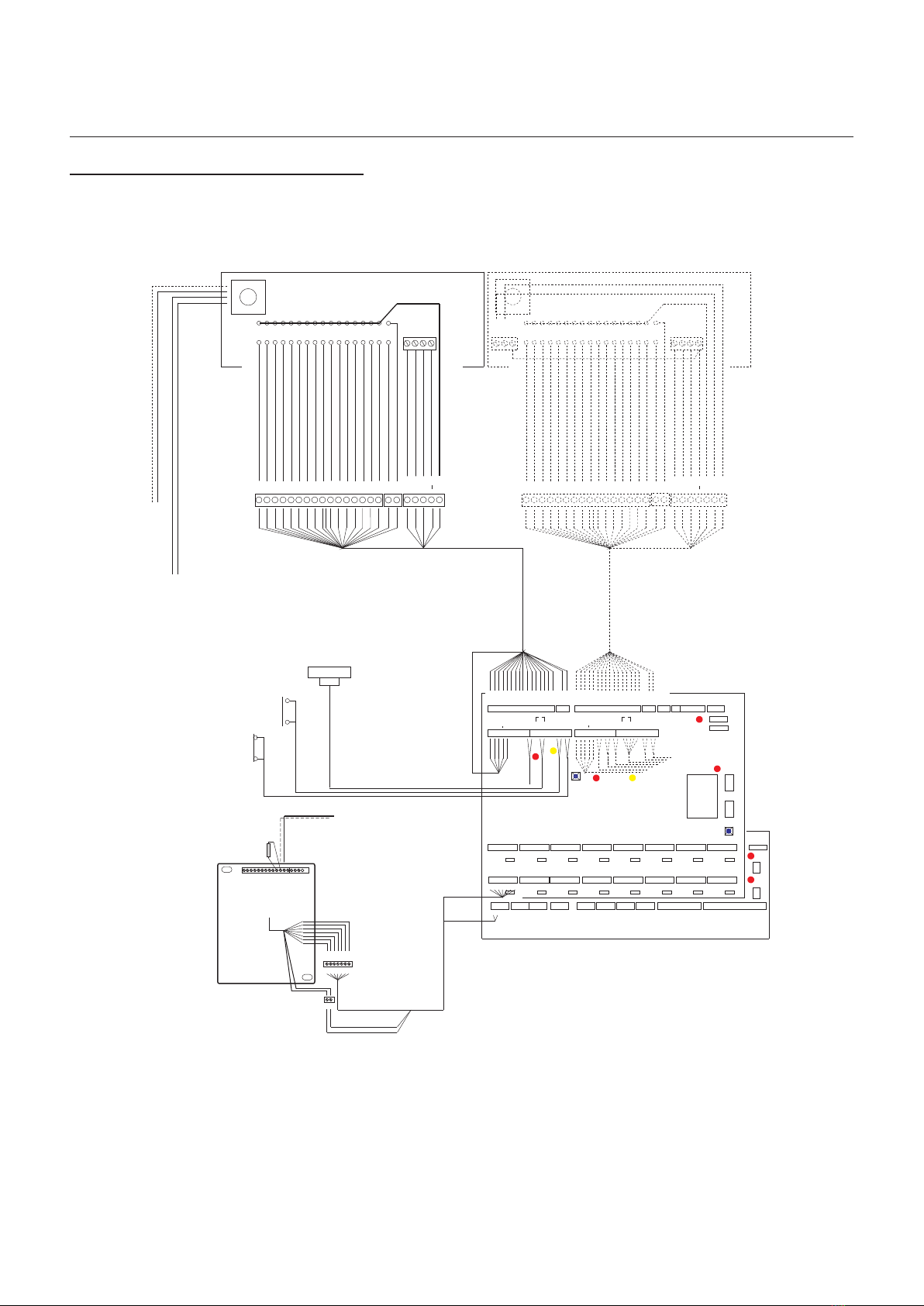
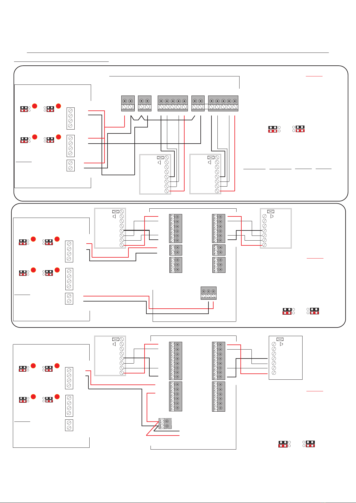
Functional System Wiring Overview
- 6 -
(See Video Monitor wiring detail)
PANEL 1
PANEL 2
3
4
5
6
7
8
9
10
11
12
13
14
15
16
1
2
3
4
5
6
7
8
9
10
11
12
13
14
15
16
1
2
1
1,C
2
6
9
PS
PL
DL
1,C
2
6
9
PS
PL
DL
1,C
2
6
9
PS
PL
DL
1,C
2
6
9
PS
PL
DL
1,C
2
6
9
PS
PL
DL
1,C
2
6
9
PS
PL
DL
1,C
2
6
9
PS
PL
DL
1,C
2
6
9
PS
PL
DL
1,C
2
6
9
PS
PL
DL
1,C
2
6
9
PS
PL
DL
1,C
2
6
9
PS
PL
DL
1,C
2
6
9
PS
PL
DL
1,C
2
6
9
PS
PL
DL
1,C
2
6
9
PS
PL
DL
1,C
2
6
9
PS
PL
DL
1,C
2
6
9
PS
PL
DL
CC
DML
SBL
RTE
RTE
FS
FS
SA
SE
LC
LAC ac
LAC
RTE T
2
+
Tx
Rx
OV
OV
OV
OV
TX
TX
B+
B--
FUNCTION
Digital Time Clock
DATA
TC
TC
12V
12V
12V
1
CC
DML
SBL
RTE
RTE
FS
FS
SA
SE
LC
LAC
LAC
RTE T
RTE T
DMS
ac
DMS
RTE T
DMS
DMS
2
+
LINE 2
LINE 1 LINE 3
LINE 4
LINE 5
LINE 6
LINE 7
LINE 8
LINE 9
LINE 10
LINE11
LINE 12
LINE 13
LINE 14
LINE 15
LINE 16
ENTER
RESET
Door Contact Switch
Request to Exit Switch
(Timed)
Lock Release
ac/dc
PAC
TR
TR
PAC
TR
TR
Video Monitor
System Controller
0
0
dc
dc
2 Amp Fuses
Lock Release Button
Privacy Button
Privacy On Indicator
Door Monitoring Indicator
75 Ohm (End of Line)
Resistor
R1
R2
1.C
2
6
9
PS
DL
PL
AMA-1202/BRK Mono & AMA-1702/BRK Colour Video
Monitor connection plate
Monitor
Video Coax
To Video
Distributor
L
I
N
E
1
+
-
+
-
+
-
+
-
+
-
+
-
+
-
+
-
+
-
+
-
+
-
+
-
+
-
+
-
+
-
+
-
Vout
Scn
CamR
CamDP
Cam2P
Cam1P
Scn
Scn
Scn
Scn
+
+
+
+
-
-
-
-
-
+
Camera Power x 5
Camera Power x 5
Cam1L
Cam2L
Scn
Scn Distribution
-+
Sbl1
Sbl2
3
4
5
6
7
8
9
10
11
12
13
14
15
16
1
2
1
CC
2
+
TR
TR
TR
TR
FUNCTIONAL ENTRANCE PANEL
3
4
5
6
7
8
9
10
11
12
13
14
15
16
1
2
1
CC
DML
SBL
2
+
0
0
(See Amplifier wiringdetail)
(See Amplifier wiring detail)
DML
-0
SBL
LANDING ENTRANCE PANEL
To Video Input
To Camera Power Input
Functional Video
Installation Manual
Functional Video
Revision 1.8 Date: 10/03/2009
- 7 -
Functional Video Panel wiring detail
Dual/DDA Video Panel wiring detail
System Video Controller Entrance Panel
PANEL 1
3
4
5
6
7
8
9
10
11
12
13
14
15
16
1
2
Brown of White
Note:
See Camera detail
White of Brown
Slate of White
White of Slate
Red of Orange
Orange of Red
Green of Red
Red of Green
Brown of Red
Red of Brown
Black of Blue
Blue of Black
Black of Orange
Orange of Black
Green of Black
Black of Green
Blue of White
White of Blue
Blue of Red and Red of Blue
White of Orange and Orange of White
Slate of Red and Red of Slate
Black of Slate
Slate of Black
Red of Blue
Black of Brown
Brown of Black
1
CC
DML
SBL
FCL
2
+
TR
TR
0
Vout
Scn
CamR
CamDP
Cam2P
Cam1P
Cam1L
Cam2L
Scn
Scn
Scn
Scn
Scn
Scn
Video Output
Video Output
Panel Camera1 Input
Panel Camera1 Input
Panel Camera2 Input
Panel Camera2 Input
Camera Supply x 5
+
+
+
+
-
-
-
-
-
+
Sbl1
Sbl2
System Video Controller Entrance Panel
PANEL 1
3
4
5
6
7
8
9
10
11
12
13
14
15
16
1
2
Brown of White
White of Brown
Slate of White
White of Slate
Red of Orange
Orange of Red
Green of Red
Red of Green
Brown of Red
Red of Brown
Black of Blue
Blue of Black
Black of Orange
Orange of Black
Green of Black
Black of Green
Blue of White
White of Blue
Blue of Red and Red of Blue
White of Orange and Orange of White
Slate of Red and Red of Slate
Black of Brown
Brown of Black
1
CC
DML
SBL
2
+
TR
TR
0
Camera Supply x 5
Vout
Scn
CamR
CamDP
Cam2P
Cam1P
Cam1L
Cam2L
Scn
Scn
Scn
Scn
Scn
Scn
Video Output
Video Output
Panel Camera1 Input
Panel Camera1 Input
+
+
+
+
-
-
-
-
-
+
Note:
See Camera detail
Camera
Camera
FCL
DML
SBL
1
+
-
0
BUSY
FLAT CALLED
TALK NOW
ENTER
Functional Video
Installation Manual
Note:
See page 8 for
wiring detail
Distribution
-+
1
2
+
-
1
2
+
-
Functional Video
Revision 1.9 Date: 15/12/2010
Note:
See Amplifier detail
Page 8
Note:
See Amplifier detail
Page 8
Panel Amplifier
To
Controller
-
+
1
2
Intercall
Functional
Panel Amplifier
To
Controller
-
+
1
2
Intercall
Functional
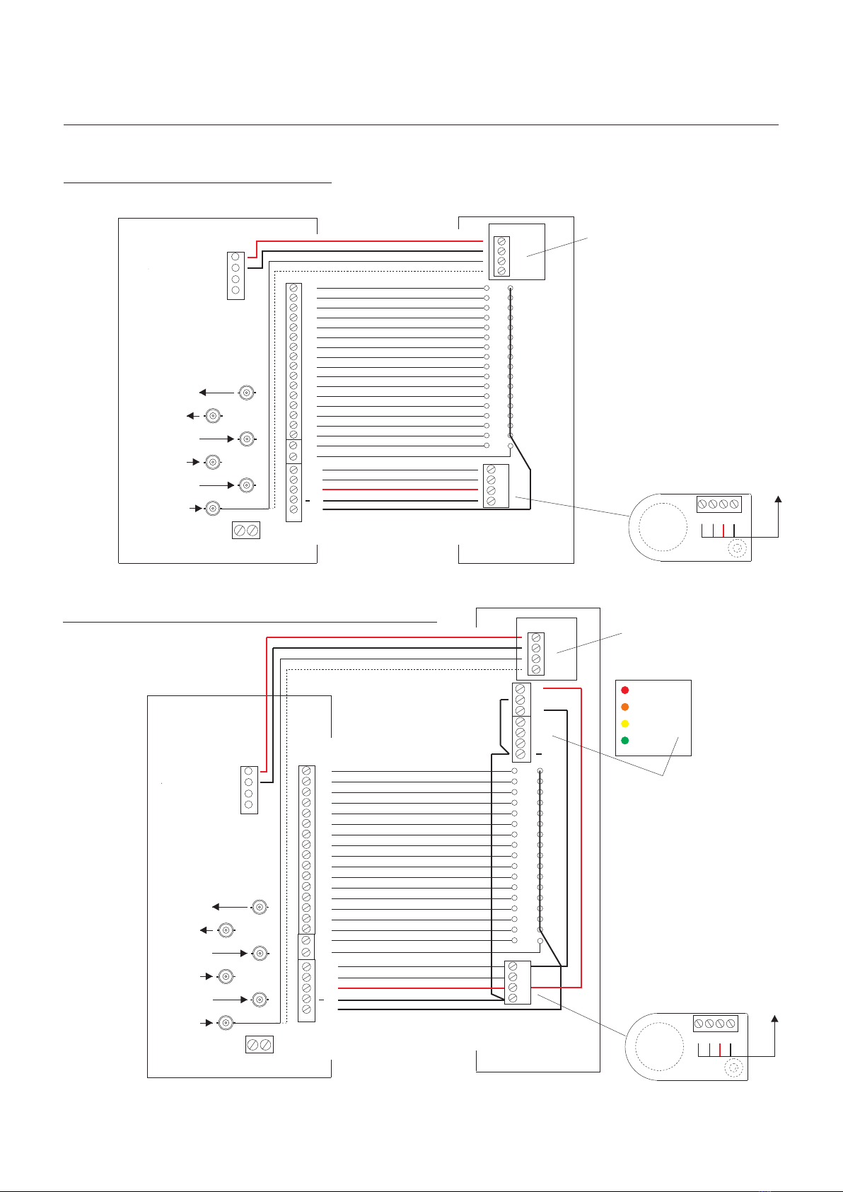
Functional Video Panel wiring detail
Entrance Panel
PANEL 1
3
4
5
6
7
8
9
10
11
12
13
14
15
16
1
2
Brown of White
White of Brown
Slate of White
White of Slate
Red of Orange
Orange of Red
Green of Red
Red of Green
Brown of Red
Red of Brown
Black of Blue
Blue of Black
Black of Orange
Orange of Black
Green of Black
Black of Green
Blue of White
White of Blue
Blue of Red and Red of Blue
White of Orange and Orange of White
Slate of Red and Red of Slate
Black of Brown
Brown of Black
1
CC
2
+
TR
TR
0
Note:
See Camera detail
Camera
Functional Video
Installation Manual
1
2
+
-
Camera
Supply
x 2 12V
12V
0V
0V
Distribution
-+
Output To Video
Distributors
Video Output
To Next Controller
Digital Panel
2 Input
Digital Panel
1 Input
Functional Panel
Camera1 Input
Functional Panel
Camera 2 Input Cam1P
CamDP1
CamDP2
CamR
VOUT
Cam2P
System Video Controller
- 7A -
Functional Video Panel with DDA display wiring detail
Entrance Panel
PANEL 1
3
4
5
6
7
8
9
10
11
12
13
14
15
16
1
2
Brown of White
Note:
See Camera detail
White of Brown
Slate of White
White of Slate
Red of Orange
Orange of Red
Green of Red
Red of Green
Brown of Red
Red of Brown
Black of Blue
Blue of Black
Black of Orange
Orange of Black
Green of Black
Black of Green
Blue of White
White of Blue
Blue of Red and Red of Blue
White of Orange and Orange of White
Slate of Red and Red of Slate
Black of Brown
Brown of Black
1
CC
2
+
TR
TR
0
Camera
FCL
DML
SBL
1
+
-
0
BUSY
FLAT CALLED
TALK NOW
ENTER
Note:
See page 8 for
wiring detail
1
2
+
-
Camera
Supply
x 2 12V
12V
0V
0V
Distribution
-+
Output To Video
Distributors
Video Output
To Next Controller
Digital Panel
2 Input
Digital Panel
1 Input
Func Panel
Camera1 Input
Functional Panel
Camera 2 Input Cam1P
CamDP1
CamDP2
CamR
VOUT
Cam2P
System Video Controller
Functional Video
Revision 1.9 Date:14/12/2010
Note:
See Amplifier detail
Page 8
Note:
See Amplifier detail
Page 8
Panel Amplifier
To
Controller
-
+
1
2
Intercall
Functional
Panel Amplifier
To
Controller
-
+
1
2
Intercall
Functional
Functional Video
Installation Manual
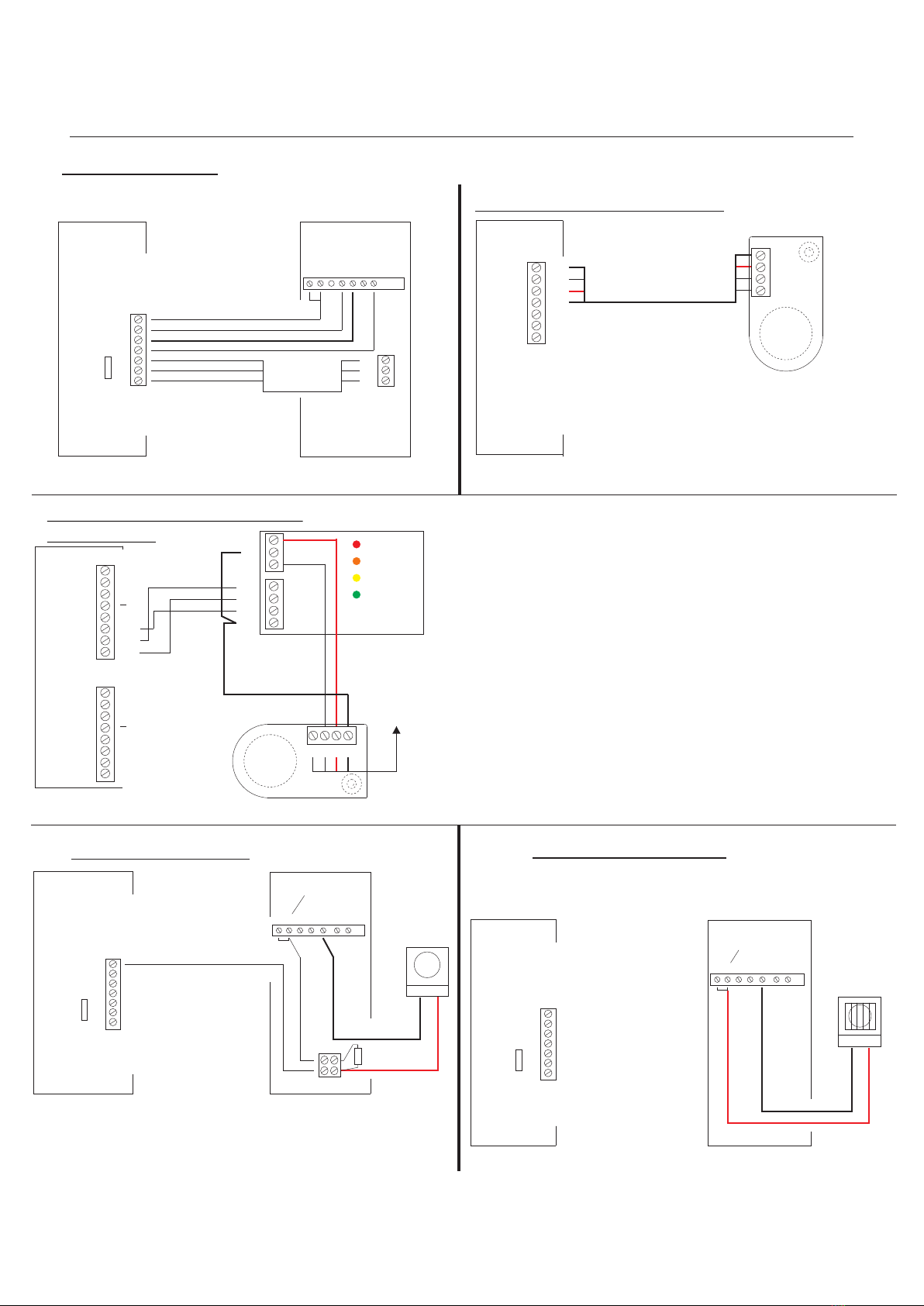
Strobe wiring detail Sounder wiring detail
Note:
Please refer to the Controller Programming
Instruction sheet in the Functional &
Digital Installation Manual on how to initiate the
powering of the Strobe.
1,C
2
6
9
PS
PL
DL
CA1 2 6 10 9
Standard call input
connection
System Controller Telephone Handset
LINE 1
Sounder
RedBlack
CA1 2 6 10 9
Standard call input
connection
Blue of White
Telephone Handset
1,C
2
6
9
PS
PL
DL
LINE 1
Strobe
RedBlack
+
100uf
35V
System, Controller
AT-PID Telephone
Privacy, Privacy On Indicator and
Door Monitoring Indicator wiring detail
1 6CA 9102
PS
PL
DL
Blue of White
White of Blue
White of Orange and Orange of White
White of Green
Green of White
Brown of White
White of Brown
System Controller AT-PID Telephone Handset
1,C
2
6
9
PS
PL
DL
LINE 1
Lock Release Button
Privacy Button
Privacy On Indicator
Door Monitoring Indicator
Entrance Panel DDA Display
wiring detail
- 8 -
Functional Video
Revision 1.9 Date: 14/12/2010
1
CC
DML
SBL
FCL
2
+
PANEL 1
0
1
CC
DML
SBL
FCL
2
+
PANEL 2
0
BUSY
FLAT CALLED
TALK NOW
ENTER
_
1
SBL
FCL
DML
0V
+
System Controller
Panel Amplifier
To
Controller
-
+
1
2
Intercall
Functional
Panel Amplifier wiring detail
System Controller
Amplifier (See Amplifier wiring detail)
1
CC
DML
SBL
2
+
-0
PANEL 1 Blue of White
White of Blue
Blue and Red Pair
White of Orange and Orange of White
Panel Amplifier
-
+
1
2
Intercall
Functional

- 9 -
Functional Video
Installation Manual
For Fail Safe (SA) Lock Releases.
Emergency Override Switch
For Fail Secure (SE)
Lock Releases
wire N/O to RTE/T only.
SA
SE
LC
LS2
LS -
RTE/T
RTE/T
DMS
DMS
PANEL 1
Common
1
Normally
Open
4
Normally
Closed
2
RTE
N/C
N/O
Request To Exit (Timed) wiring detail
System Controller
RTE/T
RTE/T
DMS
DMS
Green of White
White of Green
Request To Exit Switch
(Timed)
Intercall
Digital
RTE
Request To Exit Button
12VDC Auxiliary Output wiring detail
PANEL 1
OV
OV
OV
12V
12V
12V
12VDC Auxiliary Output )
12VDC Auxiliary Output )
3Amp Overall Output
12VDC Auxiliary Output )
System Controller
System
Controller
Emergency Override
Switch
For Fail Secure (SE) Lock Releases.
PANEL 1
RTE/T
RTE/T
Green of White
White of Green Common
1
Normally
Open
4
Normally
Closed
2
External Time Clock wiring detail
If an on board Digital time clock is
fitted, and a secondary clock
(BST/GMT) is required please set all
on board trades times to zero.
System Controller
TX
B+
TC+
TC-
12V
0V
TX
B -
NO NCCOM PWR
Magnetic Locks
with Door
Contact
Functional Video
Revision 1.8 Date: 10/03/2009

- 10 -
DC Fail Secure Lock Release wiring detail
System Controller
Fail Secure Lock Release DC
PANEL 1
Door Monitoring Contact
( If Specified )
Green of White
To Fire Switch N/O Contact
White of Green
1N4007
Diode +
SA
SE
LC
LS2
LS -
RTE/T
RTE/T
DMS
DMS
Note:
a) If Door Monitoring is not required, then link DMS to DMS with a wire link.
b) It is important that a 1N4007 diode is fitted at the lock release if you are using the System
Controller for lock release power, This is to protect the System Controller against back EMF .
If the locks are being powered by a PAC Controller then use the MOV supplied with the PAC reader.
DC Fail Safe Lock Release wiring detail
System Controller
Fail Safe Lock Release DC
Door Monitoring Contact
( If Specified )
Green of White
White of Green
IN4007
Diode +
Request To Exit N/C
(If Specified)
Fire Switch N/C
(If Specified)
SA
SE
LC
LS2
LS -
RTE/T
RTE/T
DMS
DMS
Functional Video
Installation Manual
Functional Video
Revision 1.8 Date: 10/03/2009

- 11 -
Functional Video
Installation Manual
Proximity Access wiring detail
SelectLine Controller
VIN
0V
The RED LED’s
must always be
illuminated on
both jumpers
except on lock
release.
PANEL 1
PAC -
PAC+
TR
TR
PANEL 2
PAC -
PAC+
TR
TR
PAC
DDA
READER
DO CLK
0V
VCA
D1/SIG
10.5-28V
*
Lock 2 Relay 2
N/C
N/O
COM
N/C
N/O
COM
Lock 1 Relay 1
N/C
N/O
COM
N/C
N/O
COM
DOOR 2
+V
LED
I/P
RTE
DC
SIGA
SIGB
0V
DOOR 1
+V
LED
I/P
RTE
DC
SIGA
SIGB
0V
PAC EASINET 512
SelectLine Controller
PAC Easikey 99
P2P1 L1 L2
Power Lock1
Note:
PAC Recommended cable:
7/0.2mm (0.22mm2) 4-core or
6-core unscreened cable or
CW1308 0.5dia Multipair cable.
+V2 10.5/28V
D1/SIG
n/c
VCA
0V
Channel1 Channel2 Reader Colour
Black
Yellow
White
Blue
Red
S2
R2
A2
+V1
S1
R1
A1
-V1 -V2
L3 L4
Lock2
Reader1
-V1 S1 R1 A1 +V1
Reader2
-V2 S2 R2 A2 +V2
PAC
DDA
READER
DO CLK
0V
VCA
D1/SIG
10.5-28V
*
PAC
DDA
READER
DO CLK
0V
VCA
D1/SIG
10.5-28V
*
Fail Safe 2 second
Lock Output
System Controller
The RED LED’s
must always be
illuminated on
both jumpers
except on lock
release.
PANEL 1
PAC -
PAC+
TR
TR
PANEL 2
PAC -
PAC+
TR
TR
0V
12V
NO
PAC
WITH
PAC
NO
PAC
WITH
PAC
NO
PAC
WITH
PAC
NO
PAC
WITH
PAC
NO
PAC
WITH
PAC
NO
PAC
WITH
PAC
Both Door Times be
programed to 2 seconds
Fail Safe even if only one
reader is being used.
Must
Both Door Times be
programed to 2 seconds
Fail Safe even if only one
reader is being used.
Must
Both Door Times be
programed to 2 seconds
Fail Safe even if only one
reader is being used.
Must
SelectLine Controller
Lock2
Reader2
+V
LED
RTE
DC
SIG
GND
Relay 2
N/C
COM
N/O
B+
B-
DCIN
L+
L-
Lock1 Relay 1
Reader1
+V
LED
RTE
DC
SIG
GND
N/C
COM
N/O
L+
L-
PAC EASIKEY 1000
System Controller
The RED LED’s
must always be
illuminated on
both jumpers
except on lock
release.
PANEL 1
PAC -
PAC+
TR
TR
PANEL 2
PAC -
PAC+
TR
TR
PAC
DDA
READER
DO CLK
0V
VCA
D1/SIG
10.5-28V
*
0V
12V
System Controller
0V
12V
Functional Video
Revision 1.8 Date: 10/03/2009
- 11A -
Functional Video
Installation Manual
Proximity Access wiring detail
Functional Video
Revision 1.8 Date: 10/03/2009
VIN
0V
PAC
DDA
READER
DO CLK
0V
VCA
D1/SIG
10.5-28V
*
PAC
DDA
READER
DO CLK
0V
VCA
D1/SIG
10.5-28V
*
Lock 2 Relay 2
N/C
N/O
COM
N/C
N/O
COM
Lock 1 Relay 1
N/C
N/O
COM
N/C
N/O
COM
DOOR 2
+V
LED
I/P
RTE
DC
SIGA
SIGB
0V
DOOR 1
+V
LED
I/P
RTE
DC
SIGA
SIGB
0V
PAC EASINET 512
Note:
PAC Recommended cable:
7/0.2mm (0.22mm2) 4-core or
6-core unscreened cable or
CW1308 0.5dia Multipair cable.
+V2 10.5/28V
D1/SIG
n/c
VCA
0V
Channel1 Channel2 Reader Colour
Black
Yellow
White
Blue
Red
S2
R2
A2
+V1
S1
R1
A1
-V1 -V2
Both Door Times be
programed to 2 seconds
Fail Safe even if only one
reader is being used.
Must
Both Door Times be
programed to 2 seconds
Fail Safe even if only one
reader is being used.
Must
Both Door Times be
programed to 2 seconds
Fail Safe even if only one
reader is being used.
Must
Lock2
Reader2
+V
LED
RTE
DC
SIG
GND
Relay 2
N/C
COM
N/O
B+
B-
DCIN
L+
L-
Lock1 Relay 1
Reader1
+V
LED
RTE
DC
SIG
GND
N/C
COM
N/O
L+
L-
PAC EASIKEY 1000
12VDC
Power
Supply
12 3
12 3
12 3
12 3
WITH
PAC
NO
PAC
123
123
123
123
WITH
PAC
NO
PAC
12 3
12 3
12 3
12 3
WITH
PAC
NO
PAC
PAC Easikey 250
P2P1 L1 L2
Power Lock1
L3 L4
Lock2
Reader1
-V1 S1 R1 A1 +V1
Reader2
-V2 S2 R2 A2 +V2
PAC
DDA
READER
DO CLK
0V
VCA
D1/SIG
10.5-28V
*
PAC
DDA
READER
DO CLK
0V
VCA
D1/SIG
10.5-28V
*
PAC
DDA
READER
DO CLK
0V
VCA
D1/SIG
10.5-28V
*
PAC
DDA
READER
DO CLK
0V
VCA
D1/SIG
10.5-28V
*
Fail Safe 2 second
Lock Output
SelectLine Controller
Functional Audio Controller
PANEL 1
PAC -
PAC+
TR
TR
PANEL 2
PAC -
PAC+
TR
TR
0V
12V
The RED LED’s must
always be illuminated
on both jumpers
except on lock
release.
NO
PAC
WITH
PAC
12 3
12 3
12 3
12 3
NO
PAC
WITH
PAC
12 3
12 3
12 3
12 3
SelectLine Controller
Functional Audio Controller
PANEL 1
PAC -
PAC+
TR
TR
PANEL 2
PAC -
PAC+
TR
TR
0V
12V
The RED LED’s must
always be illuminated
on both jumpers
except on lock
release.
NO
PAC
WITH
PAC
12 3
12 3
12 3
12 3
NO
PAC
WITH
PAC
12 3
12 3
12 3
12 3
SelectLine Controller
Functional Audio Controller
PANEL 1
PAC -
PAC+
TR
TR
PANEL 2
PAC -
PAC+
TR
TR
0V
12V
The RED LED’s must
always be illuminated
on both jumpers
except on lock
release.
NO
PAC
WITH
PAC
12 3
12 3
12 3
12 3
NO
PAC
WITH
PAC
12 3
12 3
12 3
12 3

Functional Video
Installation Manual
- 12 -
Functional Video Controller
Camera
Supply
x 2 12V
12V
0V
0V
Output To Video
Distributors
Video Output
To Next Controller
Digital Panel
2 Input
Digital Panel
1 Input
Func Panel
Camera1 Input
Functional Panel
Camera 2 Input Cam1P
CamDP1
CamDP2
CamR
VOUT
Cam2P
System Controller
+
-
Video Distributor wiring detail
Monitor
Video Coax
+
-
+
-
R2
R1
1.C 1
2 2
6 6
9 9
PS X2
PL X1
DL Y1
L
I
N
E
1
Functional Video
Controller
AMA-1202/BRT Video Monitor
connection plate
RD
R3
R2
1
2
6
CA
R1
R1
V4
V5
V3
10
9
X1
X2
Y1
Y2
Video Monitor wiring detail
Distributor
Remove all Jumpers on the Distributors
except the LAST in line.Normally
removed during manufacturing
TC+
TC-
SIG
Entrance Panel 1
Camera
SCN
EARTH
EARTH
Sig
+-Scn
4, 8, 12 and 16 Video Distribution Box
U1 U2 EU5 U3 U4
Video Distributor R2
+-
R1
Monitor Coax
Monitor Coax
Monitor Coax
Monitor Coax
12-18VDC
Distributor Power
1,C
2
6
9
PS
PL
DL
R1
R2
V3/U1-U4
V5/SCR
Blue of White
White of Blue
White of Orange & Orange of White
White of Green
Green of White
Brown of White
White of Brown
Grey of White & White of Grey
Red of Blue & Blue of Red
RG59 Coaxial Cable (Core)
RG59 Coaxial Cable (Screen)
Functional Video
Revision 1.8 Date: 10/03/2009

Distributor
Remove Jumperss except
the LAST Distributor in line.
500mA Quick Blow Fuse
+ Distribution
-Distribution
SIGnal
SCReen
Earth Continuity
Video Coax To Riser
Controller VOUT
Distribution Supply To Riser Controller
4, 8, 12 and 16 Video Distribution wiring detail
U1 U2 EU5 U3 U4
Video Distributor
R2
+-
R1
U1 U2 EU5 U3 U4
Video Distributor
R2
+-
R1
U1 U2 EU5 U3 U4
Video Distributor
R2
+-
R1
U1 U2 EU5 U3 U4
Video Distributor
R2
+-
R1
ALL PRE-WIRED
EARTH
CONTINUITY
- 12A -
Functional Video
Installation Manual
Functional Video
Revision 1.8 Date: 10/03/2009

System Controller Summary
Connection Detail
Controller
1,C
2
6
9
PS
PL
DL
R1
R2
1
2
+
-
DML
SBL
CC
TR1
TR2
RTET
RTET
LC
SA
SE
PAC
Tx
Rx
0V
Video Monitor
Speaker/Electronic Call
Microphone
Common
Lock Release
Privacy Switch
Privacy On Indicator
Door Monitoring Indicator
0V Monitor Supply
12VDC Monitor Supply
Panel Amplifier Detail
Speaker
Microphone
+6VDC
-6VDC
Entrance Panel Detail
Door Monitor/Release Indicator
System Busy Indicator
Button Common
Trades Detail
Trades Button
Trades Button
Request To Exit (Timed)
Request To Exit (Timed)
Lock Release Detail
Lock Common (DC)
Fail Safe (DC)
Fail Secure (DC)
PAC Detail
PAC Pre-wired Lock Release
Serial Connection
Transmit
Receive
Common
Controller
TC
TC
Note: N/O Clean Contacts
0V
12V
Note: 3 Amp (3 x 12VDC)
Overall Output
TX
TX
B+
B-
Trades Clock
Secondary Trades Clock
Secondary Trades Clock
Auxiliary Supplies
3 x 0V Output
3 x 12VDC Output
Power Input to Controller
12Vac Input
12Vac Input
Battery Back Up
+12VDC Battery Input
0V Battery Input
- 13 -
Functional Video
Installation Manual
Functional Video
Revision 1.8 Date: 10/03/2009

System Controller Summary cont...
Connection Detail
Controller
0V
12V
Note: 3 Amp (3 x 12VDC)
Overall Output
TX
TX
B+
B-
Sbl1
Sbl2
+ )
) Distribution
- )
Vout
Scn
CamR
Scn
CamDP
Scn
Cam2P
Scn
Cam1P
Scn
Cam1L
Scn
Cam2L
Scn
+ )
) Camera Supply
- )
R1 )
) Monitor Output
R2 )
Auxiliary Supplies
3 x 0V Output
3 x 12VDC Output
Power Input to Controller
12VAC Input
12VAC Input
Battery Back Up
+12VDC Battery Input
0V Battery Input
System Busy Output to Functional Panel
Panel 1 Busy Indicator
Panel 2 Busy Indicator
Video Distribution
+ 18VDC Distributor Supply
0V Distributor Supply
Video Inputs and Outputs
Video Signal Output to Distributor
Video Screen Output to Distributor
Video Riser Signal Output
Video Riser Screen Output
Video Digital Panel Camera Signal Input
Video Digital Panel Camera Screen Input
Video Functional Panel 2 Camera Signal Input
Video Functional Panel 2 Camera Screen Input
Video Functional Panel 1 Camera Signal Input
Video Functional Panel 1 Camera Screen Input
Video Lobby/Landing Panel 1 Camera Signal Input
Video Lobby/Landing Panel 1 Camera Screen Input
Video Lobby/Landing Panel 2 Camera Signal Input
Video Lobby/Landing Panel 2 Camera Screen Input
Camera 12Vdc Output x 5
+ 12VDC Camera Supply
- 0V Camera Supply
Monitor Supply
18VDC Monitor Supply
0V Monitor Supply
- 14 -
Functional Video
Installation Manual
Functional Video
Revision 1.8 Date: 10/03/2009
This manual suits for next models
1
Table of contents


