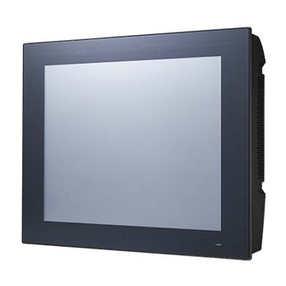
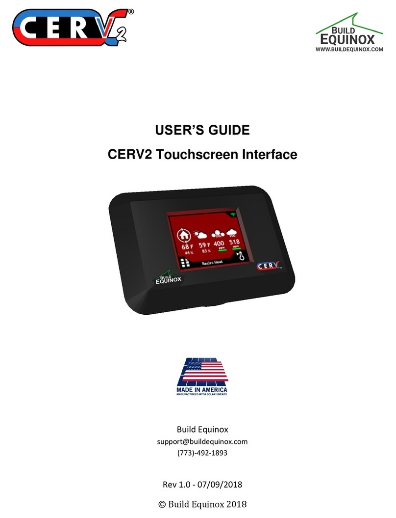
Self Climat SmartBox 1 User manual

Translatio
Pos
:
2
/Anleit
u
ngen
A5/Bilder/Piktogramme/Länd erkennze
ichen@
0\mod_1302072502909_817.docx @
9146@ @ 1
=== Ende der Liste für Textmarke
Länderkennz eichen ===
A
Smar
t
Electro
Pos: 8 /Anleitungen A5/Te xtmarken/Inha lts verzeichnis/Bild / Ke nnzeic
h
Pos: 6 /Anleitungen A5/Bi lder/Piktogramm e/Elektronik /28 Sm artb ox 1
+
S
=== Ende der Liste für Textmarke Bild ===
Pos: 9 /Anleitungen A5/Te xtmarken/Inha lts verzeichnis/Inhaltsverzeich
n
CONT
E
ABOUT
T
MODIFI
C
GENER
A
OPERA
T
ASSEM
B
START
U
MENU...
EXAMP
L
NOTES
O
OPERA
T
PERFO
R
REPAIR
S
MAINTE
N
DISPOS
A
LIST OF
TECHNI
C
FORES
E
Pos: 10 /Anlei tungen A5/ STANDARD MODULE/Übersc hri ften/Zu dies
e
ABOU
T
Pos: 11 /Anlei tungen A5/ STANDARD MODULE/Übersc hri ften/Änderun
MODIFI
Pos: 12 /Anlei tungen A5/ Ele ktro ni k/Smartbox/Än de rung S mar tBox @
2
R
Pos: 13 /---Seitenu mbruch A5 --- @ 0 \m od_1297265391854_0.docx
@
n of original / Par
t
A
ssembly
t
Box® 1 /
n
ic Content I
h
nung @ 1\mod_1307543049496_0.doc x @ 14965 @ @ 1
2+3 @ 0\mod_1305013053123_0.docx @ 12040 @ @ 1
S
martBox®1
n
is @ 2\mod_1326793499190_817.docx @ 22951 @ @ 1
NTS
T
HESE INSTR
U
C
ATIONS COM
A
LLY................
.
T
ING MEDIA....
.
B
LY..................
.
U
P ....................
.
........................
.
L
ES FOR PRO
G
O
N PROGRAM
T
ION ................
.
R
MANCE CHE
C
S
.....................
.
N
ANCE ...........
.
A
L ...................
.
ACCESSORIE
C
AL DATA ......
.
E
EABLE FAUL
T
r Anlei tung @ 0\ mod_130086 61 184 24 _81 7. doc x @ 7777 @ @ 1
T
THESE INS
T
These i
n
Keep th
e
These i
n
that the
gen zur vorhergehenden Ausgabe @ 2\mod_1331880050656_817.docx @ 24949 @ @ 1
CATIONS C
O
2
\mod_13318006942 03_817.doc x @ 24 910 @ @ 1
R
EFERENC
E
Select the l
SmartBox®
h
3171@ @ 1
t
no. 28 100 57 d
and ope
r
SmartBo
x
ndicator - O
p
S
U
CTIONS........
.
PARED TO PR
.
.......................
.
.
.......................
.
.
.......................
.
.
.......................
.
.
.......................
.
G
RAMMING ....
.
MING .............
.
.
.......................
.
C
K....................
.
.
.......................
.
.
.......................
.
.
.......................
.
S.....................
.
.
.......................
.
T
S ....................
.
T
RUCTIONS
n
structions ar
e
e
m in a safe
p
n
structions m
u
component o
p
O
MPARED T
O
E
anguage Ge
r
h
as a 2-line L
C
r
ating inst
x
® 2 / Sm
a
p
tionally wit
h
martBox®2
.
........................
EVIOUS VER
S
.
........................
.
........................
.
........................
.
........................
.
........................
.
........................
.
........................
.
........................
.
........................
.
........................
.
........................
.
........................
.
........................
.
........................
.
........................
e
part of the p
p
lace while yo
u
st be observ
e
p
erates as int
e
O
PREVIOUS
r
man, Englis
h
C
D display.
Ver
s
ructions
a
rtBox® 3
additional f
u
S
m
........................
ION .................
........................
........................
........................
........................
........................
........................
........................
........................
........................
........................
........................
........................
........................
........................
........................
roduct.
u are using th
e
d and hande
d
e
nded and to
VERSION
h
or French (
m
s
ion 03.2012 / Re
p
3
u
nctions
m
artBox®3
........................
........................
........................
........................
........................
........................
........................
........................
........................
........................
........................
........................
........................
........................
........................
........................
........................
h
e product.
d
over to the
o
comply with t
h
m
enu step 1
8
p
laces version 07
.
Pos: 4 /Anleitu ngen A5/Bi ld er/Piktogramme/Pi ktogra mme/CE @ 0 \mo
d
@ 1
=== Ende der Li ste für Textmarke Kennzeichnun g ===
........................
.
........................
.
........................
.
........................
.
........................
.
........................
.
........................
.
........................
.
........................
.
........................
.
........................
.
........................
.
........................
.
........................
.
........................
.
........................
.
........................
.
o
perator to en
h
e warranty t
e
8
).
.
2011
_1304512113206_0.docx@ 11083@
.
...... 1
.
...... 1
.
...... 2
.
...... 2
.
...... 3
.
...... 4
.
...... 6
.
...... 9
.
.... 10
.
.... 12
.
.... 12
.
.... 12
.
.... 12
.
.... 12
.
.... 13
.
.... 14
.
.... 15
sure
e
rms.
Self Climat

SmartBox® 1 / SmartBox® 2 / SmartBox® 3
2 / 16 Part no.
28 100 57 d
Pos: 14/An leitungen A5/STANDARDMO DULE /Übersc hri ft en/Al lg emeines @ 1\ mo d _132 14 4 76 00 0 20_8 1 7. d oc x @ 20 9 43 @ @ 1
GENERALLY
Pos: 15/An leitungen A5/Elektroni k/Smartbox/1+2+3/Allgemeines SB 1 ,2,3@ 0 \mo d _1 30 501 67 15 6 66 _ 81 7.d oc x @ 12 0 89 @ @ 1
The electronic tank management system SmartBox®1, 2 and 3can be used for monitoring of
the liquids contained in unpressurized liquids tanks.
In addition to the registration of tank content, other functions can be implemented by system
enhancements, e. g. temperature measurement, data telecommunication, system fault or
connection to master control systems of the building.
The SmartBox®2has additional relay control functions, e. g. for activating external alarm
devices, solenoid valves, or the dry-run protection function of pumps.
The SmartBox®3has relay control functions and an audible alarm for minimum or maximum
level indication. Whentheacousticalarmsounds,itcanbeswitchedoffbypressingthe‘Quit’
key.
Pos: 16/An leitungen A5/Elektroni k/Smartbox/Bauk as tensy stem @1\mo d _1 30 74 3 90 3 98 6 9_ 81 7. d oc x @ 14 8 46 @ @ 1
Thanks to its modular design, the system can be equipped with additional modules, e. g. with
an analogue interface or a GSM module for telecommunication.
Pos: 17 /Anleitu nge n A5/Ele ktroni k/Smartbox/M essgerät ni cht für Abre chnungszwecke geeic ht@ 1 \mo d _1 30 743 89 72 8 99 _8 1 7.d oc x @ 14 8 31 @ @ 1
The indicated measurements are not gauged for invoicing.
Pos: 18/An l eitunge nA5 /Elektron i k/Smart box/1+ 2+3/ SB1+2+3 2 -zeiligesDisplay@1\mo d _1 30 7 43 91 5 932 4_ 81 7. d oc x @ 14 8 61 @ @ 1
SmartBox®1, 2 and 3 has a 2-line LCD display and a measuring input for connecting the
probe. The SmartBox®2also has additionally 2 programmable relays with make and break
switching output. The SmartBox®3has a programmable relay with make and break switching
output and an acoustic alarm for minimum or maximum level indication.
Pos: 19/An leitungen A5/Elektroni k/Son d e/Tank anschlus s @ 0 \mo d _1 30 50 3 00 067 62 _8 1 7. d oc x @ 12 1 80 @ @ 1
By default, the measuring probe can be installed with tank connecting threads G1, G1 1/2 or
G2.
Pos: 20/An leitungen A5/Elektroni k/Smartbox/Betrie bs medie n@ 0 \mo d_ 1 30 501 70 46 9 20 _8 1 7.d oc x @ 12 1 04@ @ 1
OPERATING MEDIA
Fuel oil EL acc. to DIN 51603-1
Standard probe
Hydraulic oil, Motor oil fresh oil
Urea solution e. g. AdBlue
®
acc. to DIN 70700
Liquid fertiliser e. g. AHL
Water
Diesel fuel DK acc. to DIN EN 590
on request
fuel oil in storage tanks
Glycol
Waste oil
Paraffin
Petrol flashpoint < 55 °COnly with ex-proof probe + protective
tube + ex-proof barrier
Other media on request!
Pos: 21 /Anleitu nge n A5/STAND ARDMODULE/All ge meine Sic herheitshin wei se/Sich erheitshin weis Öl @ 1\ mo d _131 90 0 97 36 4 59_8 1 7. d oc x @ 20 5 70 @ @ 1
WARNING
Leaking liquid fuels, such as fuel oil.
May cause you to slip and injure yourself and is also a hazard for groundwater.
Capture fuels during maintenance.
Observe the relevant laws and regulations.
Pos: 22/--- Seitenumbr uch A5--- @ 0\mod _1 29 72 6 53 918 54 _ 0. d oc x @ 31 71 @ @ 1
Self Climat

SmartBox® 1 / SmartBox® 2 / SmartBox® 3
Part no. 28 100 57 d 3 /
16
Pos: 23/An leitungen A5/STANDARDMO DULE /Allg emeine Sicherhe it shinw eise/Sic herheits hi nweis Elektronik Außer ha lb Ex-Zone@ 1\mo d_ 1 31 90 0 98 140 09 _8 1 7. d oc x @ 20 5 90 @ @ 1
DANGER
May not be used in explosion-prone areas.
May cause an explosion or fatal injuries.
Must be installed by a specialist company in accordance with local industrial
health and safety regulations.
Installation outside the defined ex zone.
Pos: 24 /Anleitu nge n A5/STAND ARDMODULE/Überschriften /M ontage @ 0 \mo d _1 30 10 4 5732 8 68 _8 1 7.d oc x @ 827 5 @ @ 1
ASSEMBLY
Before assembling, check that the product is complete and has not suffered any damage
during transport.
Pos: 25/An leitungen A5/STANDARDMODULE/Fachbetrieb nach W asserrec ht @0 \mo d _1 30 21 6 5362 2 78 _8 1 7.d oc x @ 934 5 @ @ 1
ASSEMBLY, STARTUP and MAINTENANCE are to be carried out by a specialised
company in terms of water law.
Pos: 26/An leitungen A5/STANDARDMODULE/FachgerechteI ns tallation@ 0 \mo d _1 30 459 44 06 4 24 _8 1 7.d oc x @ 11 3 28@ @ 1
For the system to function as intended it must be installed professionally in compliance with
the technical instructions applicable to the planning, construction and operation of the entire
system.
Pos: 27/An leitungen A5/Elektroni k/Smartbox/UVV-BGS @ 0 \mo d _1 30 503 76 26 1 36 _ 81 7.d oc x @ 12 2 40 @ @ 1
These regulations also include the accidentpreventionregulationsoftheemployers’ liability
insurance associations, the VDE regulations, and the installation and operating instructions.
Pos: 28/An leitungen A5/Elektroni k/Smartbox/Montage hinweis 230V @ 0\mo d _1 30 50 3 74 667 57 _8 1 7. d oc x @ 12 2 25 @ @ 1
Notes on installation
The housing of the indicator is suitable for wall mounting and is connected to the 230 V mains
supply. Under normal circumstances, the indicator must be operated with the housing cover
closed. It is installed and commissioned by a qualified technician while the unit is open.
CAUTION
Keep away from the area of the 230 V terminal.
Pos: 29 /Anleitu nge n A5/Ele ktroni k/Smartbox/M ontage An zeig eg erät @ 0\ mo d _130 5 03 59 4 47 6 5_81 7. d oc x @ 12 2 10 @ @ 1
Installation of the indicator
Mount the indicator to the wall in a suitable position. After loosening the four screws, open the
indicator by removing the cover. Mount the unit to a smooth vertical wall by means of dowels.
Mount the housing of the indicator by the four fixing holes by means of the enclosed screws.
Take care not to damage the housing! After connecting the terminals and setting the unit up,
replace the cover.
Pos: 30 /Anleitu nge n A5/Ele ktroni k/Smartbox/En tnahmeabsp erru ng öffnen @ 0\ mo d _130 50 9 97 4 51 68_ 81 7. d oc x @ 12 2 90 @ @ 1
Re-open the take-off line of the tank and reactivate the oil burner if applicable. Check the
function of the oil burner.
Pos: 31/An leitungen A5/Elektroni k/Son d e/M ontage M esssonde @1\mo d _1 31 17 7 629 83 9 6_ 81 7.d oc x @ 178 99 @ @ 1
Assembly Measuring probe
SeeAssemblyandoperatinginstruction„Measuringprobe“,Part No. 28 801 50.
Pos: 32/An leitungen A5/Elektroni k/Smartbox/Versorg ungsspannung @ 0 \mo d _1 30 5 10 352 21 0 1_ 81 7.d oc x @ 123 20 @ @ 1
Connection of supply voltage:
Voltage: 230 V AC 50 Hz
Connection: Terminals PE,N+Lto the indicator (cable not included in the delivery)
Pos: 33/--- Seitenumbr uch A5--- @ 0\mod _1 29 72 6 53 918 54 _ 0. d oc x @ 31 71 @ @ 1
Self Climat

SmartBox® 1 / SmartBox® 2 / SmartBox® 3
4 / 16 Part no.
28 100 57 d
Pos: 34/An leitungen A5/Elektroni k/Smartbox/1+2+3/Anschlus s Relaiskonta k te SB2+3@ 0\mod _1 30 51 0 36 963 87 _ 81 7. d oc x @ 12 3 35 @ @ 1
Connection of the relay contacts at the indicator SmartBox®2 und SmartBox®3
The indicator SmartBox®2 has two relay contact pairs (SmartBox®3one) for the
connection of external control circuits or for activating external alarm or signal devices.
In case of failure of the unit and if the fill level (or optionally the temperature) is above the
selected limit, the contacts of relay terminals 6 + 7 and 9 + 10 are closed, or 5 + 6 and 8 + 9
are open –see the legend on the PCB in the unit.
Switching voltage max.250 V AC
Switching current max.3,5 A
Connection normally open (NO)
normally closed (NC)
Relay 1terminals 5 + 6 terminals 6 + 7 only SmartBox 2
Relay 2terminals 8 + 9 terminals 9 + 10 SmartBox 2+3
Pos: 35/An leitungen A5/Elektroni k/Smartbox/1+2+3/Anschlus s Schnittstelle z uSB 4+5+PC @ 0 \mo d _1 30 51 0 4046 2 39 _ 81 7.d oc x @ 12 3 50 @ @ 1
Connection of interface to SmartBox®4, SmartBox®5 or PC set
The measured values can be transmitted to the SmartBox®4, SmartBox®5 or the PC set via
the integrated interface“SERIALLINKOUTPUT”terminals3 + 4.
Pos: 36/An leitungen A5/Elektroni k/Smartbox/Inbetri e bnahm e@ 0 \mo d_ 1 30 510 65 34 7 17 _8 1 7.d oc x @ 12 3 80@ @ 1
STARTUP
Operation elements and display
The device is adjusted once when it is put into operation. After startup the device operates in
display mode with the top closed.
From device version V4.xx the display is a two-line LCD display with 2 x 16 characters.
The display has green background lighting for best readability in all lighting conditions.
Pos: 37/An leitungen A5/Elektroni k/Smartbox/1+2+3/In betrieb nahme Displ a y 1+ 2+3@ 1 \mo d _1 30 76 1 70 641 19 _ 81 7. d oc x @ 15 1 00 @ @ 1
SmartBox®1/2/3 has the following display:
The device is adjusted via the three small blue
buttons:
[MINUS] [PLUS] [ENTER]
These are located on the motherboard between
the terminals.
Select the language (German, English or
French) in menu step 18.Language (see page
11).
After the level indicator has been installed, it
can be started up.
Before programming, you need to ascertain the tank data and enter the values into the right
column input value of the following table. Then, enter the values for the individual entry steps.
Optionally, the device can also be programmed as explained in the enclosed Quick Guide.
Pos: 38/An leitungen A5/Elektroni k/Smartbox/Eins tellun gPar ameter @ 0 \mo d _1 30 51 1 11 200 26 _8 1 7. d oc x @ 12 3 95 @ @ 1
Setting a
parameter:
Press ENTER to open setup mode.
Select the desired setting parameter via PLUS.
Press ENTER to call up the value selection for the parameter.
Set the value with PLUS/MINUS, press ENTER to save.
Quitting the
setup mode:
You can quit the setup mode at any time.
Select“8. Exit“andpressENTER
to go back to the standard display mode.
Pos: 39/--- Seitenumbr uch A5--- @ 0\mod _1 29 72 6 53 918 54 _ 0. d oc x @ 31 71 @ @ 1
Liquid
Lit
r
e
Percent
Self Climat

SmartBox® 1 / SmartBox® 2 / SmartBox® 3
Part no. 28 100 57 d 5 /
16
Pos: 40/An leitungen A5/Elektroni k/Smartbox/1+2+3/Sc haltungsbeis piel SmartBox 1 @ 0\mo d _1 30 51 0 5267 1 30 _8 1 7.d oc x @ 123 65 @ @ 1
Fuel oil tank -wiring example SmartBox®1
Pos: 41/An leitungen A5/Elektroni k/Smartbox/1+2+3/Sc haltungsbeis piel SmartBox 2 @ 0 \mo d _1 30 51 2 45 895 36 _8 1 7. d oc x @ 12 6 05 @ @ 1
Rain water reservoir -wiring example SmartBox®2
Pos: 42/--- Seitenumbr uch A5--- @ 0\mod _1 29 72 6 53 918 54 _ 0. d oc x @ 31 71 @ @ 1
water for
domestic use
probe
measuring
Relay 1: 6-7 = break contact
=> pump safe to run dry
Relay 2: 8-9 = make contact
=> automatic backfeed
control system
oil tank
measuring probe
storm
water
reservoir
feed pump
drinking water
network
solenoid valve for
backfeed
optional switch
Self Climat

SmartBox® 1 / SmartBox® 2 / SmartBox® 3
6 / 16 Part no.
28 100 57 d
Pos: 43 /Anle itungenA5/Ele ktr oni k/Smar tbox/1+2+3/Ei ngabefunktion 1-2 S B 1 +2 + 3 @ 0\mo d _1 3051 1 13 77 8 03 _81 7. d oc x @ 124 10 @ @ 1
MENU
Menu Input function Input value
1.Measure
probe
Select probe measuring range (see type label of
the probe) -default value is 250 mbar
Standard probe
Tank height max. for Medium
heating oil
water
100mbar 1.20 m 1.00 m
150mbar 1.80 m 1.50 m
160mbar 1.90 m 1.60 m
200mbar 2.40 m 2.00 m
250mbar 2.90 m 2.50 m
400mbar 4.70 m 4.00 m
500mbar 6.00 m 5.00 m
1000mbar 12.00 m 10.00 m
2000mbar 24.00 m 20.00 m
3000mbar 36.00 m 30.00 m
5000mbar 60.00 m 50.00 m
Set mbar
by Calibration
Is only indicated if item 10. Set h
or 11. Set V has been activated
________mbar
2.Liquid Select the medium
Medium Measuring range kg/m³ (15 °C
)
Heating oil 845 kg/m³ -default setting
Water 999
Diesel 830
Biodiesel880
RME, FAME 880
Rapeoil 915
Palm oil 910
Motor oil 865
AdBlue 1090
Regular
gasoline
743
Premium
gasoline
750
Density valve
Entry of a specific probe with
different measuring range
by Calibration
Is only indicated if item 10. Set h
or 11. Set V has been activated
_____________
If the density of the stored medium is unknown, the reference height can be entered in menu
item 10. Set h. To do this, determine the current fill level in mm, deduct 1,0 cm from it and
enter the resulting value - click YES to confirm the entry.
Should the current fill level be less than 75%, we urgently recommend that you adjust the
value after the next refuelling to achieve good measuring accuracy.
Pos: 44/--- Seitenumbr uch A5--- @ 0\mod _1 29 72 6 53 918 54 _ 0. d oc x @ 31 71 @ @ 1
Self Climat

SmartBox® 1 / SmartBox® 2 / SmartBox® 3
Part no. 28 100 57 d 7 /
16
Pos: 45/Anl eitunge nA5 /Ele ktron ik/Smartbox/Eingabefunkti on 3SB1+2+3+4+4 Pro @ 2\mod _1 33 29 1 48 1 907 2_ 81 7. d oc x @ 25 5 28 @ @ 1
3.Tank shape
Tank shape
Linear Default setting
linear tank, rectangular tanks, vertical cylinders,
basement-welded steel tanks.
Cylindric
horiz.
cylindrical tank (optionally, see Cyl.>50 m³),
horizontalcylinders;tubulartanks,max.45m³;typical
shape for steel outdoor or buried tanks.
Ball-
shaped
spherical tank; buried tanks with spherical
basic shape; frequently plastic buried tank (GRP).
Oval oval basement tanks; typical shape of GRP
tanks and single-walled sheet metal tanks
Convex Plastic battery tanks, convex,
slightly convex shape, alternative to linear
Concave Plastic battery tanks, concave,
slightly concave shape, alternative to linear
Holed
plastic
Plastic tank with recess
Plastic tank with a large recess (hollow) in the center
(without tape bindings)
Cyl.
> 50,000 L
large cylindrical outdoor tank 50,000 litres to
100,000 litres; a special bearing chart conversion
table can be ordered specifically for large cylindrical
tanks of 50 m³ to 100 m³.
Bearing
chart
Enter a special tank shape from existing bearing chart.
For this purpose, up to 16 value pairs (height in mm +
volume in L) can be entered.
Before the value pairs are entered, the values for the
tank volumes must be entered in step 4 and for the
tank height in step 5.
Index: 0 0 cm 0
L
Index: 1 xxx.xcm xxxx L
Index: 2 . cm L
Index: 3 . cm L
max.
Index: 16 max. cm max. L
Specified value pair (do not have to
be entered).
first value pair entered
max. inside height of tank the
max. tank volume (= 5.Tank height)
is allocated automatically and does
not have to be entered.
Not all 15 intermediate value pairs (Index: 1–15) have to be entered.
A linear interpolation is made between 2 interpolation values. For a linear range of the tank
geometry it is sufficient to enter a lower and an upper value pair.
Pos: 46/--- Seitenumbr uch A5--- @ 0\mod _1 29 72 6 53 918 54 _ 0. d oc x @ 31 71 @ @ 1
Not linear
Not linear
L
inear
Self Climat

SmartBox® 1 / SmartBox® 2 / SmartBox® 3
8 / 16 Part no.
28 100 57 d
Pos: 47/An leitungen A5/Elektroni k/Smartbox/1+2+3/Eingabefunkti on 4- 8 @ 0\mo d _1 3051 1 49 73 8 63 _81 7. d oc x @ 12 4 40 @ @ 1
4.Tank
volume
Adjust the tank volume with [+] [-] (100%). The default
setting is 0 L. The value must be set.
Please see a volume table for the highest value,
if available.
For a 100 m³ cyl. buried tank, this may for example
be the value 100,600 litres.
___________L
5.Tank
height
Enter inner tank height in millimetres:
e. g.: 249,0 cm (max. value = 999,9 cm)
(height without dome)
Please see a volume table for the highest value,
if available.
For a 100 m³ cyl. buried tank, this may for example
be the value 288,0 cm.
_________mm
Steps 6 + 7 are only required for SmartBox
®
2 and SmartBox
®
3
6.Relay 1
or
SmartBox 2
6.Acoustic
alarm
(Buzzer)
SmartBox 3
Switch function of relay 1 or buzzer:
Deactive
The relay does not switch in relation to
the content
Active The relay switches in relation to the
content
ON Forces the relay to energise (fix ON)
OFF
Forces the relay to de
-
energise (fix OFF)
Example of switch point setting for Active (with
hysteresis):
Enter switching points as % values from 01-99 (and/or
enter as °C value from -99 to +99 only for probe with
temperature measurement)
deactive activate with + / -to
active press Enter to confirm
On 10% ON: set with + / -Enter
Off 12% OFF: set with + / -Enter
On +0°CON: set with + / -Enter
Off +0°COFF: set with + / -Enter
Deactivate the relay or buzzer via deactive or input
of 0% or 0°C(for On and Off).
ON _______%
OFF _______%
ON _______°C
OFF ______°C
7.Relay 2
SmartBox
2+3
See 6. Relay 1 for the data for Relay 2 ON _______%
OFF_______%
ON _______°C
OFF ______°
C
8.Exit Press Enter to return to display mode
After performing entry steps 1-7, the programming process is completed. After confirmation of
step“8.Exit“,thedeviceautomaticallyreturnstodefault display mode; the current tank content
is shown in the display.
Special functions are available under entry steps 9 to 24(see page 10).
After the end of setup, do not forget to replace the housing cover!
Pos: 48/--- Seitenumbr uch A5--- @ 0\mod _1 29 72 6 53 918 54 _ 0. d oc x @ 31 71 @ @ 1
Self Climat

SmartBox® 1 / SmartBox® 2 / SmartBox® 3
Part no. 28 100 57 d 9 /
16
Pos: 49/An leitungen A5/Elektroni k/Smartbox/1+2+3/Programmi e rbei spiel e 1+2+3 @ 0 \mo d_ 1 30 51 1 71 792 23 _8 1 7. d oc x @ 12 4 55 @ @ 1
EXAMPLES FOR PROGRAMMING
Example 1
:
Basement tank for 6,000 litres heating oil, litr
e indication, linear steel tank
Inner height 165 cm, (fill level 125 cm)
SmartBox
®
1
Standard probe 0
–
250 mbar
Step Entries / selection
1. Probe 250 mbar 250 mbar
2. Medium: Heating oil Heat.oil
3. Tank shape: linear Linear
4
.
Tank volume: 6,
000 lit
r
e
s
6,
000L (set with +/
-
keys)
5
.
Inner tank height: 165 cm
165.0cm (set with +/
-
keys)
6. Exit press ENTER to see the indication 4,550 L 76 %
Example
2
:
Well, 7.50 m maximum water level from ground of the well
(fill level 4.20 m)
relay switching function is desired.
SmartBox
®
2
Standard p
robe 0
–
1000 mbar,
indication in m water column.
Step Entries / selection
1. Probe 1000 mbar 1000 mbar
2
.
Medium: water
H2O
3
.
Tank shape (well shape): linear
Linear
4
.
Max. value 7,
500 li
t
r
e
s (
Display
m)
7,500 L (set with +/
-
keys)
5. Inner tank height 7.50 m 7,500 mm (set with +/- keys)
6. Relay 1 –On at 99 %-10 % -Off at < 10 % active On: 99 % Off: 10 %
7. Relay 2 –no function deactive
8. Exit press PLUS key to go to
9
.
I
ndicated unit: m
Unit: m
13.Rounding: automatic automatic (just confirm with ENTER)
14
.
Exit
press ENTER to se
e the indication
4.20 m
56 %
Example
3:
Buried tank, cylindrical, horizontal, for 100,600 litres diesel oil
Inner height 2.886 m, (fill level 54 cm)
SmartBox
®
3
Standard probe 0
–
250 mbar
Limit value message on the device at minimum level <25 %
Step Entries / selection
1. Probe 250 mbar 250 mbar
2
.
Medium: Diesel
Diesel
3. Tank shape cyl. horizontal >50 m³ Cyl. > 50,000 L
4. Tank volume: 100,600 litres 100,600 L (
exact value from volume table)
5. Inner tank height: 2,886 mm 2,886 mm (
exact value from volume table)
6. Acoustic alarm –On at <25 % - Off
at >27 %
active On: 25 % Off: 27 %
7. Relay 2 –no function deactive
8
.
Exit
press ENTER to se
e the indication
12
,
800 L
13 %
Pos: 50/--- Seitenumbr uch A5--- @ 0\mod _1 29 72 6 53 918 54 _ 0. d oc x @ 31 71 @ @ 1
Self Climat

SmartBox® 1 / SmartBox® 2 / SmartBox® 3
10 /16 Part no.
28 100 57 d
Pos: 51 /Anleitu nge n A5/Ele ktroni k/Smartbox/Be hä lter mit In nenhülle @ 0 \mo d _1 3051 1 90 40 1 11 _81 7. d oc x @ 124 70 @ @ 1
Tank with inner casing
For tanks with inner casing (e. g. cyl. horizontal or basement-welded tanks), the entries for
inner height and volume should be adjusted.
Examples:
Wall thickness of inner casing 0.5 cm reduce value for inner height by approx. 1 cm,
reduce volume for 10 m³ by 1.3 %, for 20 m³ by 1 %, for 50 m³ by 0.8 % and for 100 m³
by 0.7 %.
Wall thickness of inner casing 2 cm reduce value for inner height by approx. 4 cm,
reduce volume for 10 m³ by 5 %, for 20 m³ by 4 %, for 50 m³ by 3 %and for 100 m³
by 2.5 %.
Pos: 52/An leitungen A5/Elektroni k/Smartbox/1+2+3/Sonderei nstellun gen 9 -26@ 0\mo d_ 1 30 51 2 0752 4 49 _8 1 7.d oc x @ 12 5 00@ @ 1
NOTES ON PROGRAMMING
Menu Setting Description
9.Offset
probe
Adjusting:
Probe zero point, electric
Position / Distance from base
Unusable capacity that is not to be displayed
ESC Exit the menu
Offset calibr. New measurement of probe zero point (electric)
Lift probe out of the liquid beforehand.
Probe bottom
gap
Distance: x cm;
normal reference is x = 0 cm, max = 99 cm
Bottom
deadstock
Suction position: y cm
Normal reference is 0 cm = complete capacity.
y > 0 cm means corresponding unusable
capacity.
Default values Reset all values to default 00.
10.Trim
height
xxx.x cm Entry option for the reference height for the 2-
point measurement, for other probe measurement
range or for an unknown density. Subtract 1.0 cm
from the actual measured level and enter this
value.
Calibrate:No
Calibrate:Yes
If activated (Yes), the display in
menu steps 1+2
is then "by comparison".
If this is entered with an almost empty tank, it is
recommended that you make a correction the
next time it is filled.
11.Trim
volume
xxx.xxx L Readjust the level display with the +/-button
Calibrate:No
Calibrate:Yes
See menu step 10. Trim height
12.Unit
L
%
m
kg
IG
UG
Default settings
1000 point: 999.900 L
100 point: 99.50 %
100 point: 2.50 m
1000 point:
999.900 kg
Imperiale Gallone 219.750 IG
US-
Gallone (US liquid gallon)
263.900 UG
Self Climat

SmartBox® 1 / SmartBox® 2 / SmartBox® 3
Part no. 28 100 57 d 11 /
16
13.
Rounding
Automatically
Without
rounding
2(0,02…200)
5(0,05…500)
10(0,1…1000)
20(0,2…2000)
50(0,5…5000)
100(1…10000)
Default settings
minimal increments
Rounding increments in relation to the set volume
set with +/- keys
14.–
17.Exit
Back to display mode
18.
Language
Language: German,English,French + / -
/ Enter
Names: ESC + / -
/ Enter
Name Tank 1: Suggested name
Letters can be changed with + / -
/ Enter
19.Exit Back to display mode
20.LCD
display
Contrast:24 Set the contrast of the LCD display
21.Device
info
Displays information about
Software version:V4.00 (e. g.)
Serial number: Tank 1: SN=1234 (e. g.)
Offset + Gain:X0 =4.05 mA; B = 1268 (
Tank 1)
22.Test
current
Test function for the current mA value of the
measurement probe: ADC = 28A0 = 04.00 mA
If level probe is not submerged, the value should
be close to 4 mA. Tolerance range is 3.7...4.3
mA. For larger deviations, see menu item 9.
23.Test
Relay
SBox 2+3
Rel1 ON / OFF Relay test
24.Reset
ESC
Reset
the device software:
Exit this function without executing it.
Restart Initialisation. The device software restarts and
keeps all device settings.
Factory
settings
Complete reset of all parameters to the original
delivery status.
26.Exit Back to display mode
Pos: 53/--- Seitenumbr uch A5--- @ 0\mod _1 29 72 6 53 918 54 _ 0. d oc x @ 31 71 @ @ 1
Self Climat

SmartBox® 1 / SmartBox® 2 / SmartBox® 3
12 /16 Part no.
28 100 57 d
Pos: 54 /Anleitu nge n A5/STAND ARDMODULE/Überschriften /Bedie nung nic ht erford erl ich @ 1 \mo d _1 32 15 4 1004 2 31 _ 81 7.d oc x @ 210 80 @ @ 1
OPERATION
The product requires no operation while it is running.
Pos: 55/An leitungen A5/Elektroni k/Smartbox/Funkt io nskontrolle@ 0 \mo d _1 30 512 21 49 7 68 _ 81 7.d oc x @ 12 5 45 @ @ 1
PERFORMANCE CHECK
We recommend that you check the displayed litre values once per year to make sure that they
are correct.
For a simple check, pull the level probe up by its cable so that it hangs above the liquid.
In this status the display device should show 0 litres (+ tolerance).
Checking the level probe signal can be checked through menu item 22:
At 0 cm fill levelapprox. 3,7 –4,3 mA
If the deviation is greater, we recommend an offset comparison of the probe, see device
menu "9. Offset probe" and, if necessary, adjustment via "10. Trim height".
New level probe:
If a new level probe has to be installed, first reset the system to the "default values" in
"9. Offset probe".
Pos: 56 /Anleitu nge n A5/STAND ARDMODULE/Überschriften /Instan ds etzung nach Bedi enu ng , Inbetrieb na hme @ 0 \mo d _1 3044 2 57 80 9 08 _81 7. d oc x @ 109 48 @ @ 1
REPAIRS
If the measures explained above under STARTUP and OPERATION do not result in regular
STARTUP, and if there is no dimensioning problem, the product must be sent to the
manufacturer for a check. Our warranty does not apply in cases of unauthorised interference.
Pos: 57/An leitungen A5/Elektroni k /Smartbo x/1+2 +3/Instan ds etz ung Fehl er meld ung @ 0\mo d _1 30 51 2 24 886 99 _8 1 7. d oc x @ 12 5 60 @ @ 1
In case of repeated errorsor alarm messages(relay output) while the tank content does not
reach / remains below the set fill level alarm threshold at the probe element, check the
connection line of the signal and probe element for breakage or short-circuit, re-install if
necessary.
Pos: 58 /Anleitu nge n A5/STAND ARDMODULE/Überschriften /Wartung @ 2\mod _1 32 88 5 85 696 29 _8 1 7. d oc x @ 23 6 69 @ @ 1
MAINTENANCE
See PERFORMANCE CHECK.
Pos: 59/An leitungen A5/STANDARDMODULE/Entsorgen/G as / Ele ktroni k@ 0 \mo d _1 30 148 35 97 8 42 _81 7. d oc x @ 840 5 @ @ 1
DISPOSAL
To protect the environment, our products may not be disposed of along
with household waste.
The product must be disposed of via a local collection station or a recycling
station. If you do not have any possibilities for proper disposal, contact us
regarding disposal options.
Pos: 60/--- Seitenumbr uch A5--- @ 0\mod _1 29 72 6 53 918 54 _ 0. d oc x @ 31 71 @ @ 1
Self Climat

SmartBox® 1 / SmartBox® 2 / SmartBox® 3
Part no. 28 100 57 d 13 /
16
Pos: 61 /Anleitu nge n A5/Ele ktroni k/Smartbox/1 +2+3/Lis te der Zubehört ei le @ 0\mo d _1 30 512 35 77 4 49 _ 81 7.d oc x @ 12 5 90 @ @ 1
LIST OF ACCESSORIES
Order no.
Product description
Information on application
28 851 00 Data transmission
module 0-5 V DTM
-
1
Retrofittable module as interface to data transmission,
e. g. for the master control system of the building
28 853 00 Data transmission
module 4-20 mA
DTM-3
Retrofittable
module as interface to data transmission,
e. g. for the master control system of the building
28 863 00 Data transmission
module M-Bus
DTM-4
Retrofittable module as interface to data transmission,
e. g. for the master control system of the building
28 856 20 /
28 856 30
PC-set LAN /
PC-set LAN PRO
Retrofit kit for data transmission to a PC –incl.
software for indication/evaluation and for sending
messages via e-mail
28 856 25 PC-Stecker for PC-
Set LAN / PC-Set
LAN PRO
Required to connect to SmartBox
®
1, 2, 3 to a PC
28 856 26 USB-Adapter for PC-
Set LAN / PC-Set
LAN PRO
Also required to the COM connector to connect to
SmartBox®1, 2, 3 to a PC, if no free COM port is
available
28 857 00 Cable junction box IP
66, with pressure
equalization
To extend the probe cable -e. g. in the dome
28 500 00 SmartBox
®
5 - data
transmitter
GSM telecommunication system for SmartBox
®
1, 2
or 3 and event messages (e. g. burner malfunction)
28 858
00
Additional antenna Additional antenna for reception amplification at the
SmartBox®5 - data transmitter
Pos: 62/--- Seitenumbr uch A5--- @ 0\mod _1 29 72 6 53 918 54 _ 0. d oc x @ 31 71 @ @ 1
Self Climat

SmartBox® 1 / SmartBox® 2 / SmartBox® 3
14 /16 Part no.
28 100 57 d
Pos: 63 /Anleitu nge n A5/STAND ARDMODULE/Überschriften /Technische Dat en @ 1\mod_1321450820797_817.docx @ 21003 @ @ 1
TECHNICAL DATA
Pos: 64/An leitungen A5/Elektroni k/Smartbox/1+2+3/Technische Date n@ 0 \mo d _1 30 512 25 52 3 87 _8 1 7.d oc x @ 12 5 75@ @ 1
Indicator:
Supply voltage: 230 V AC 50 Hz Degree of
protection:
IP30 or IP65 acc. to
IEC 529
Power input: max. 2 VA
Measuring input: 4–20 mA; Uo= 20 V Resolution: 10 Bit
Relay output: optional (see accessories)
Switching voltage:
max. 250 V AC
Analog output:
0–5 V DC
Switching current:
max. 3,5 A 4–20 mA
Dimensions
W x H x D in [mm]:
120x120x49 (IP30) or
130x130x60 (IP65)
Housing: Polystyrene (IP30) or
Polycarbonat (IP65)
Temperature range: Ambience -10 °C to +50 °C
Probe element (relative pressure probe for level detection) / Standardprobe
Operating voltage:
20 V DC Degree of protection: IP 68 acc. to IEC 529
Material:
V4A; POM;
FPM; HD-
PE
Length of standardprobe
(without cable):
Diameter of probe:
90 mm
22 mmAccuracy: ± 1 %
Standard version:
250 mbar connection cable: 6 m
Installation position: vertically suspended, or horizontally supine
Temperature range: Ambience Operating media:-10 °C to +60 °C
Pos: 65/--- Seitenumbr uch A5--- @ 0\mod _1 29 72 6 53 918 54 _ 0. d oc x @ 31 71 @ @ 1
Self Climat

SmartBox® 1 / SmartBox® 2 / SmartBox® 3
Part no. 28 100 57 d 15 /
16
Pos: 66 /Anleitu nge n A5/STAND ARDMODULE/Überschriften /Vorhersehbare Stör ung en @ 2\mo d _132 82 5 49 0 93 11_ 81 7. d oc x @ 23 5 19 @ @ 1
FORESEEABLE FAULTS
Pos: 67/An leitungen A5/Elektroni k/Smartbox/1+2+3/Fe hlermeldungen@ 0 \mo d _1 30 5 12 127 00 3 1_ 81 7.d oc x @ 125 15 @ @ 1
Error code Significance
Error E1 The set value is invalid
Error E2 Measured value too small (< 3.5 mA probe defective)
Error E3 Measured value too great for zero point calibration (probe must not be
immersed)
Error E4 Measured value not plausible. Check menu item “9.Offset probe”
Error E5 Set height is more than the height of the tank. (incorrect entry)
Error E6
The current measured value is too low as a reference point. The probe must
be submerged. The set height is too high (the measured value is too low)
Check menu item "9. Offset probe". Otherwise, probe fault.
Error E7 The current measured value is too low in relation to the set tank height or to
the tank volume. The probe must be submerged.
Error E8 Measured value (probe current) is too high –check electrical connection and
measuring range of the probe, switch power supply off and on again. Check
menu settings steps 1 to 5. If necessary, Check menu item "9. Offset
probe". Otherwise, probe fault.
Error E9 Probe current = 0 mA –no signal current. The probe cable is poled wrongly
or interrupted; check cable extension, reconnect if necessary.
Error E10
Calibration error. Disconnect the display device from the power supply, wait
5 s and then reconnect. Otherwise, probe fault.
Error E11
WARNING:The liquid level in the tank is actually too low for an exact
measurement. You can still press [Enter] to confirm and continue.
Checking the level probe signal:
Can be checked through menu item 22:
At 0 cm fill level approx. 3.7 –4.3 mA
For 1 m water column approx. 9 -
11 mA
(for standard probe with measuring range of 250
mbar
)
Pos: 68/--- Seitenumbr uch A5--- @ 0\mod _1 29 72 6 53 918 54 _ 0. d oc x @ 31 71 @ @ 1
Self Climat

SmartBox® 1 / SmartBox® 2 / SmartBox® 3
16 /16 Part no.
28 100 57 d
Pos: 69/An leitungen A5/STANDARDMODULE/Notizen @ 0\mo d _1 30 56 3 7302 5 87 _8 1 7.d oc x @ 144 49 @ @ 1
Notes
=== Ende der Liste für Textmarke Inh alt ===
Self Climat
Self Climat
Rue des Epinettes - Z.I. SUD - F 77200 TORCY
01 60 05 18 53 Fax 01 60 17 58 39
This manual suits for next models
2
