Semtic BKDX30-95 User manual

1
CONTENT
I. Prologue............................................................................2
II. Main Instruction of Product....................................... 3
III. Installation......................................................................8
IV. Trial Running...............................................................13
V. Operation Panel Instruction.....................................15
VI. Maintenance & Repair..............................................22
Please read this manual carefully before installation
◆The heat pump must be installed by the professional technician.
◆Please install the heat pump and connect the water pipe in accordance with this manual strictly.
◆For safety, please make sure to recheck everything before power on.
◆If the machine has any improvement, the content is subject to change without notice.
Read the Manual before Operation

2
I. Prologue
Thanks for using heat pump water heater! Please read this manual carefully before installation and
operation! This manual contains the information about installation, commissioning, operation, and
maintenance. The following items should be focused:
1. Before installation, please confirm if your local voltage is match with the voltage showed on the
machine's nameplate and if the carrying capacity of the power supply, wires and sockets are suitable for
this machine's input power.
2. Users are not allowed to change the power cord or socket. Wiring work must be carried out by a
qualified electrician and ensure that the metal part of the machine has a good grounding. Changing the
ground mode is strictly forbidden.
3. After the completion of the construction of all wiring work, please make sure to recheck everything is
well before power on.
4. Installing the machine in the place which the combustible gas may leak is strictly forbidden.
5. Do not put your hands or foreign objects into the air outlet of heat pump unit, otherwise, it will be
dangerous to the people and equipment.
6. In order to obtain a better energy-saving effect, the unit should be installed in a place with
well-ventilated.
ATTENTIONS:
1. Please make sure the water systems should be filled with water before the machine start working.
2. When the machine is operating, all the valves of the water systems must be in the open position.
3. If without inlet water or stop using for a long time, when re-boot the machine, please according to the
item of attentons 1.
4. A removable filter must be installed at the water inlet and please clean the valve periodically depend
on your locate water quality (every 2 or 3 months).
5. The maximum water temperature is 55C .When you use the water, please adjust the water
temperature to a appropriate temperature (The most comfortable water temperature for shower is
38~42 , if the water temperature above 50C , there will be danger of burns!)
6. The maintenance of the machine must be carried out by the professional personnel.
7. If the unit power off,please discharge all the water inside.Otherwise,the heat exchanger will be frozen
in winter.
3
II. Main instruction of product
1.Parameter
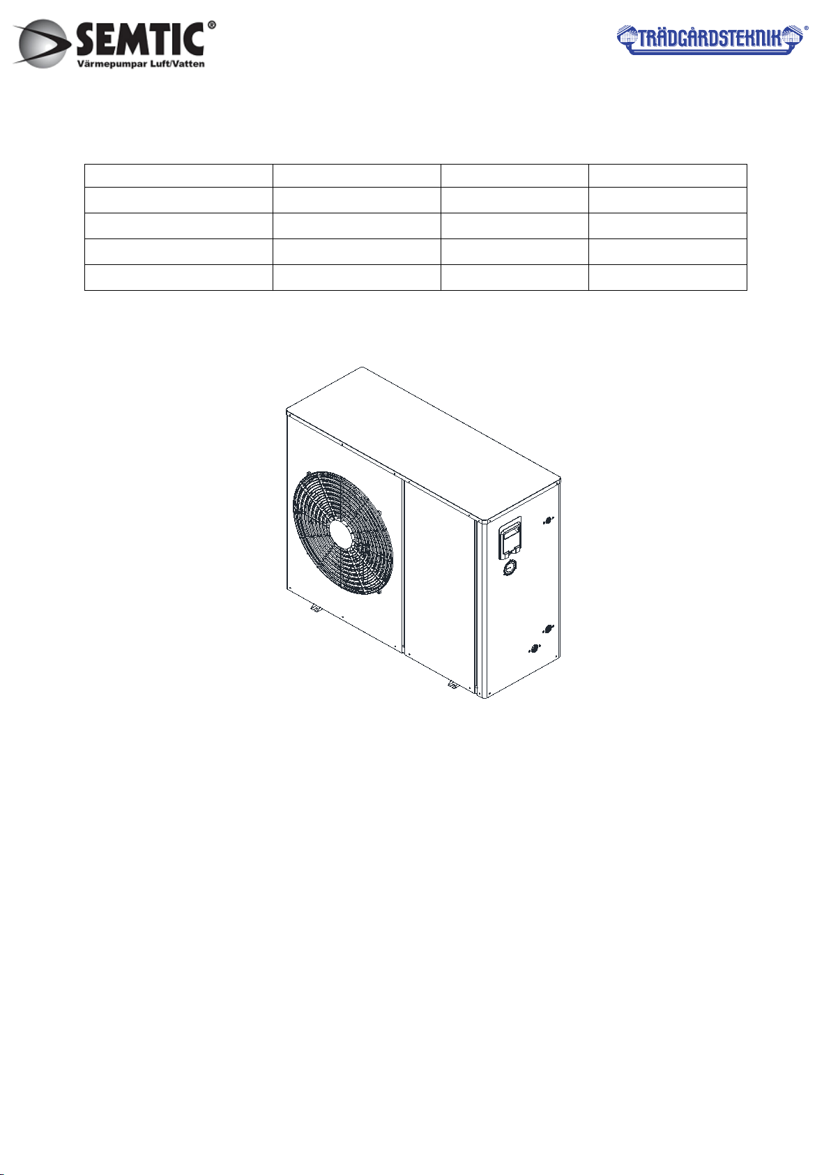
Model Size(L*W*H mm) Net Weight(KG) Power Source
BKDX30-95 1105×472×914 100 220V~50Hz/60Hz
BKDX50-200 1114×489×1257 145 380V~50Hz/60Hz
BKDX60-220 1114×489×1257 150 220V~50Hz/60Hz
BKDX80-280 1507×587×1556 185 380V~50Hz/60Hz
2.Appearance
BKDX30-95
4
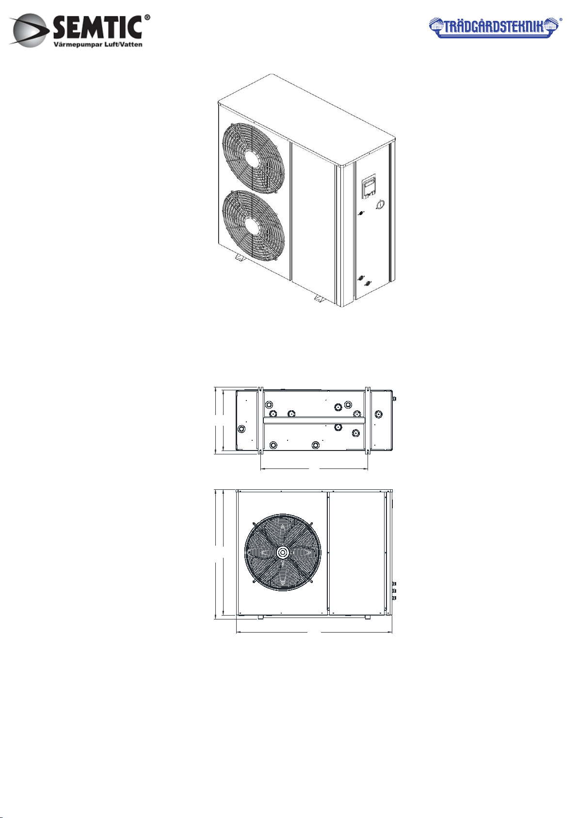
BKDX50-200, BKDX60-220
3.Appearance size
3.1 BKDX30-95
430
472
886
913.6
1105
760
3.2 BKDX50-200, BKDX60-220

5
490
1114
1256.7
509
705
1222
489
1114
G1"内 牙 接 头
G1"内 牙 接 头
G3/4"内 牙 接 头
高 压 表
抽 手
489
BKDX80-280

6
比例
1521.5
1556.5
587
592
620
104.2 964.6
出水口G1.5寸
进水口G1.5寸
62
1507
591.8
1052

7
Unit Low temperature DC Inverter monoblock heat pump
Model BKDX30-95 BKDX50-200 BKDX60-220 BKDX80-280
Waterproofing
grade
IPX4
Leakage
protection
ⅠClass
Power source
220V
~
1N/50Hz/60Hz 380V
~
3N/50Hz/60Hz
380V~3N/50HZ
Rated water
supply
165L/h 385L/h 392L/h 535L/h
Rated heating
capacity
9000W 19000W 21000W 30000W
Hot water
capacity
2200-9200W 4000-19400W 5200-21500W 6950-29200W
Heating
capacity
2600-9500W 4500-20000W 5600-22000W 5850-30000W
Cooling
heating
2500-7000W 4500-11000W 5200-13500W 7200-16600W
Heating input
power
1000-3000W 2000-5500W 2500-6600W 2660-8000W
Hot water
input power
1000-3000W 2000-5500W 2500-6600W 2660-8000W
Cooling input
power
1000-3000W 2000-5500W 2500-6600W 2660-8000W
Electrical
heating power
3000W 3000W 3000W /
Electrical
heating
14A 14A 14A /
Rated input
power
2370W 5080W 5660W 6050W
Rated current 10.5A 7.3A 26.1A 9.2A
Max current 27.1A 15.2A 45A 12A
Max input
power
5960W 8080W 8660W 8850W
Max hot water
temperature
55℃55℃55℃55℃
Rated water
flow
1.8m3/h 3.5m3/h 4.0m3/h 5.1m3/h
Refrigerant R410A/1500g R410A/2200g R410A/2700g R410A/3500g
Net weight 100kg 145kg 150kg 185kg
Noise ≤48dB(A) ≤52dB(A) ≤55dB(A) ≤60dB(A)
Inlet/outlet
gas max
4.2MPa 4.2MPa 4.2MPa 4.2MPa
High/low
pressure max
4.2MPa 4.2MPa 4.2MPa 4.2MPa
Heat
exchanger
4.2MPa 4.2MPa 4.2MPa 4.2MPa

8
4.Specifications
III. Installation
1.Heat pump installation
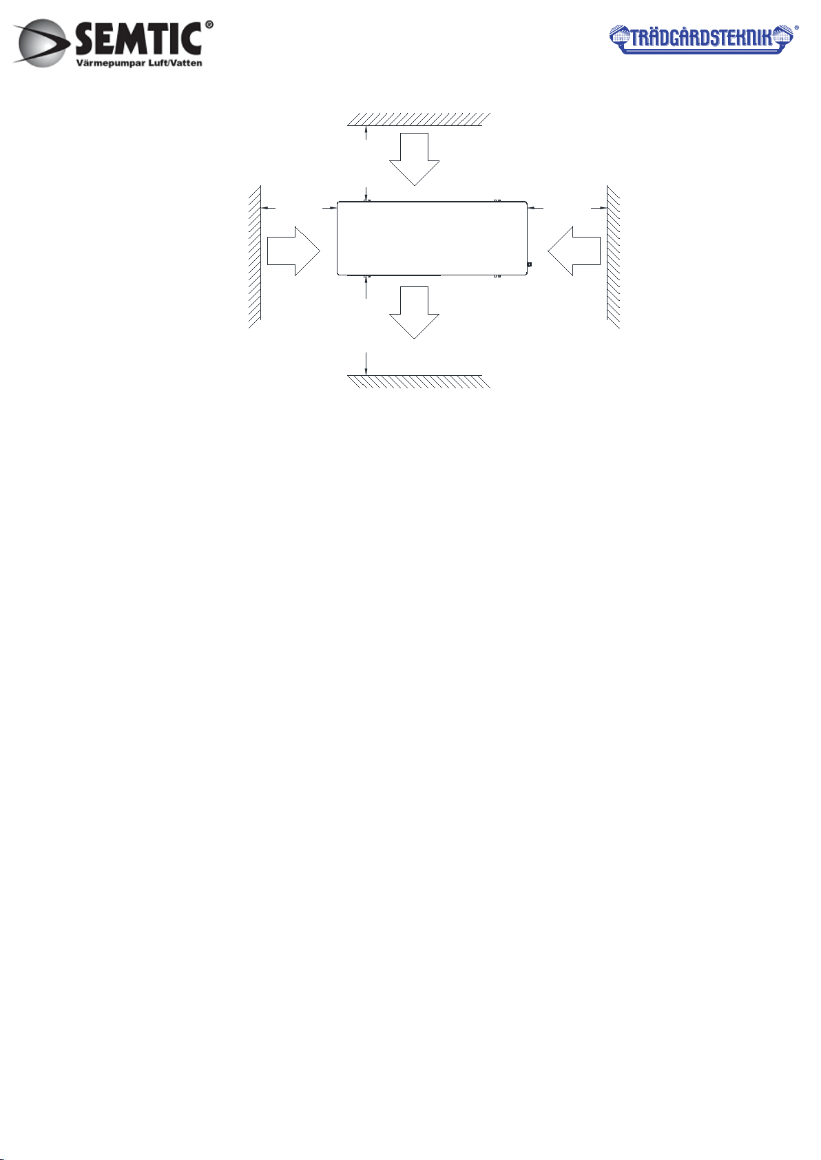
(1).Installation location
◆Provide sufficient space for installation and maintenance.
◆Inlet and outlet accessibility, strong wind cannot reach
◆Unit installed in ventilation place where can bear the weight of the unit, can mount the
unit horizontally, also will not increase the mechanical noise and vibration.
◆Exhausting air won’t affect the neighbors, no combustible gas leakage.
◆Should have the snow shed in winter.
◆Around the unit need drainage channel to drain condensate out.
◆Installation location should be easy to install, repair and connect.
◆If installed on the roof, it needs to increase measures against typhoons and lightning.
◆Do not install the control panel in the bathroom, in order to avoid moisture to affect the unit
Operation.
(2).Installed in the following locations may cause the machine to malfunction.
◆Places such as cutting oil and other mineral oils.
◆Places with salted air near the sea.
◆Places which contains gas such as sulfur, acidic or alkaline and other corrosive gases
in the spa area.
◆The place is with seriously voltage fluctuations and have strong electromagnetic waves.
◆Kitchen and other places which are full of oil odor, and oil trace.
(3).Unit infrastructure installation
Units can be installed base of concrete structures, and steel brackets can also be used to install, basic
surface is roughness (basic is designed according to the operational quality and according to the
technical performance parameters table). Under the unit, should install the vibration damping rubber, and
fix with bolts. Adjust the unit installation level, tilt <2 degrees. On the ground should have the drains for
unit's condensate.
9
Air out
≥300mm
≥2000mm ≥300mm
≥300mm
Air in
Air in
(4).Selection circulation pipeline.
Circulation pipeline of inverter heat pump can not be smaller than the inlet and outlet pipeline, circulation
pipe should use the same diameter as inlet and outlet pipes.
(5).Connection of pipeline
◆Don't let the dust and other debris into piping system.
◆Doing the plumbing work after fixing the unit firmly.
◆A removable filter (40~60mesh)must be installed at the water inlet and please regular clean the
valve depend on your local water quality.
◆Install a drain valve in the lowest point of the pipe, for convenient cleaning, Ensure smooth access
level, Can not alternately up and down, for discharge the air and draining the water in the pipe out.
◆Install the union valve at the water inlet/outlet, for convenient maintaining. Should fix the valve on
water pipe of the unit. Rotating the water pipe, water connecting can’t withstand rotation torsion directly.
◆Outlet and inlet water pipes should do thermal insulation well, the distance of outlet and inlet need to
apart, for first time to use, should add the appropriate amount of antifreeze and anti corrosive into the
warming water pipes, the input water pipe and water tank can do water replenishment according to the
actual situation.
◆Do not shut off the power in winter. If do not use for a long time, should drain off the water in the unit
and water pipes, to prevent heat exchanger or water pipe freeze and crack.
◆Select pipe material, can choose stainless steel, copper, aluminum hot water pipes, hot water PPR
pipes, etc., with pipes in national health and safety standards, heat-resistant, rust-proof, not easy to
scale.
◆Reasonable pipe layout, to minimize bending and reduce the pressure loss of the water system.
◆After the circulating water system connected, must do pipeline connection rigidity and add water
pressure inspection, and sewage, to ensure the system clean. Past the inspection,no leakage, then pack
insulation for pipeline and valves.
◆Metal pipe must use with more than 50mm thick glass fiber or high density, fire-retardant insulation
sponge. (PPR hot water pipes can be used 30mm thickness of glass fiber or high density fire-retardant
10
sponge rubber insulation.)
◆Must install thermometer and water pressure gauge on Inlet and outlet water pipes,to inspect during
operation.
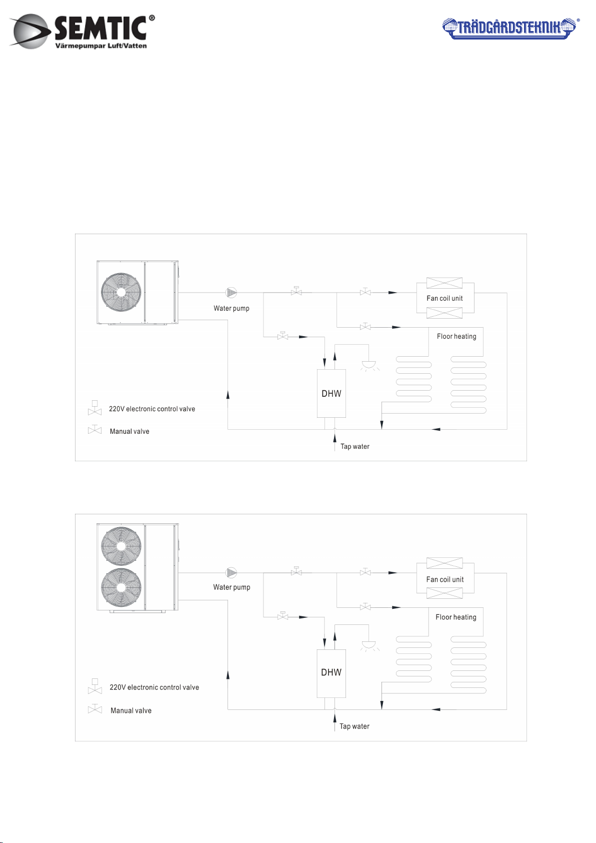
2.Connection diagram
(1)BKDX30-95
(2)BKDX50-200, BKDX60-220, BKDX80-280

11
3.Circuit connection
(1) Attentions
◆Construction wiring must be installed by a professional technician for construction in accordance with
the circuit diagram.
◆Appliance installation wiring should be installed in accordance with national wiring rules.
◆Before installation, please confirm whether your local voltage is match with the voltage showed on the
machine’s nameplate and whether the carrying capacity of the power supply, wires and sockets are
suitable for this machine’s input power.
◆The power source wire diameter is selected by the nameplate maximum current.
◆The regulation of insurance tube: according to the reality.
◆Users are not allowed to change the power cord, wiring work must be carried out by qualified
electricians, and to ensure that the machine metal parts has a good connection with grounding, the
machine shall not be allowed to change the grounding method.
◆The power connection must be equipped with the unit matching and at least 3mm contact with the
power from the all-pole disconnect device and leakage protection device.
◆If the power soft wire is damaged, it must be replaced by the manufacturer, its service department, or
similar professional to avoid danger.
◆Do not insert hands or foreign objects into the outlet of the unit, which will lead to the danger of
personnel and equipment.
◆The remote controller is fixed by screw and installed indoor with the height above 1.5M. It is forbidden
to install in the environment where the humidity, rain, acidity, corrosivity and light illuminate directly.
◆The water quality of the unit must meet the national standard of domestic water consumption,
otherwise it will cause the machine damage, the company does not bear any responsibility.

12
4.Circuit diagram
(1)BKDX30-95
(2) BKDX50-200, BKDX60-220
M
Power input
(380V/3PH/50Hz)
FM1FM2
PE4
PE5
1 2 3 4 5 6
P P P P
N1
N1 N1
L1
L2
L2
N2
N2
D1 D2 D3
R1
D+
PE
KA1
FR
FR
N3
L2 L2
L1
OUT10
N10
N4
P
PE6
PE2
RSTN
W
V
U
PE3
COM
NR S T
L1
S1 T1
R1
S1
T1
D+ D-
D-
I2
I1
U
V
W
D1 D2 D3
N1
Notice: please connect external contactor
when circulation pump power
large than 600W.
1 2:Circulating water pump.
3 4:Hot water solenoid valve.
5 6:Heating/cooling solenoid valve.
Ambient temp..(Yellow)
Coil temp..(Blue)
Exhaust gas temp..(Red)
Return gas temp..(Green)
Output water temp..(Black)
Return water temp..(White)
Water tank temp..(White)
Red Red Red
Red
Yellow
Green
Blue
Red
Yellow/Green
Blue
Yellow/Green
Yellow/Green
Yellow/Green
Yellow/Green
Yellow/Green
Red
Blue
Red
Blue
Red Red
Red Green
Red Yellow
Green
Inductor
5mH/20A
Yellow
Yellow
Wired controller
Electronic expansion valve
Red
Yellow
Green
Blue
Blue Blue
Blue
Blue
Red
Red
Pipeline herter
Four-way valve
Crankshaft heater
Chassis heater
Black
White
Red
Orange
Red
Orange
Black
White
Red Red Red
High pressure switch
Low pressure switch
Circulating water side
water flow switch
Linked switch
(short-circuit)
Antifreeze switch
(short-circuit)
CN607
I1
I2
DC+
DC-
R
S
T
V
U
W
DC-DC+
N1
GND
NRST
R1 S1 T1
N' R' S' T'
N1' S1' T1' COM_D
COM_L
DISP
SW2
CN26
NL
OUT4
N8 N7 N4
N2
OUT3 OUT1
TS5
N1
OUT5OUT6OUT7OUT8
TH1 TH2 TH3 TH4 TH5 TH6 TH7
TS3
TS4
TS1
TS2
SW1
TH8 TH9
OUT2
N9N10
OUT9
OUT10
CN2
Cooling valve

13
(3) BKDX80-280
M
COM_D
COM_L
DISP
SW2
CN26
NL
OUT4
N8 N7 N4
N2
OUT3 OUT1
TS5
N1
OUT5OUT6OUT7OUT8
OUT9
TH1 TH2 TH3 TH4 TH5 TH6 TH7
TS3
TS4
TS1
TS2
SW1
OUT10
P P P P
ST N
S1 T1
S1 T1
S1T1N1N2 N1
N2
(380V/50HZ)
1 2 3 4 5 6 PE1
W
V
U
PE3
COM
FM2FM1
PE4PE5
PE2
RST N
RST N
N1
L1
L2
N2
L2
N2 L1
N1N1N1
D1 D2 D3
D1 D2 D3
R1 S2 T3
R1
S1
T1
U
V
W
U V W
DC+ DC-
I2
I1
1 2:Circulating water pump.
3 4:Hot water solenoid valve.
5 6:Heating/cooling solenoid valve.
Power input
Notice: please connect external contactor when
circulation pump power large than 600W.
Red Red Red Red
Yellow
Green
Blue
Yellow/Green
Yellow/Green
Black
White
Crankshaft heater
Chassis heater
Four-way valve
Black Black
White
White
Red
Orange
Red
Orange
Red
Yellow
Green
Red
Yellow
Green
Red
Yellow
Green
Yellow
Inductor
Blue
Black
White
High pressure switch
Low pressure switch
Circulating water side
water flow switch
Linked switch
(short-circuit)
Antifreeze switch (short-circuit)
Wired controller
Electronic
expansion
valve
P
Ambient temp..(Yellow)
Coil temp..(Blue)
Exhaust gas temp..(Red)
Return gas temp..(Green)
Output water temp..(Black)
Return water temp..(White)
Water tank temp..(White)
IV. Trial running
1.Trial running must after all the installation completed.
2.Please confirm the following matters before the trial operation, put “√”in the boxes after
confirmation
▲ Unit is installed correctly
▲ Power supply meets unit’s rated power source need
▲ Piping and wiring are correctly installed
▲ Unit air inlet/outlet well-ventilated
▲ Drain off water is done well
▲ Leakage protective device act effectively
▲ Pipe thermal insulation
▲ Grounding wire connected correctly

14
3.After check and ensure correct, then power on. If the control panel display nothing, that should
recheck and tight the line of control panel. The control panel should display time, setting
temperature and the current temperature.
4.Discharge the air out of the pipelines , and then press ON/OFF button, the unit work under the
setting temperature, unit’s trial running would check the following:
▲ First time to run the device, check the current normal or not;
▲ Operation panel’s function keys are normal or not;
▲ The indicator light is normal or not;
▲ The whole circulating hot water system whether has water leakage;
▲ The condensed water discharge is normal or not;
▲ System’s pressure is normal or not (according to the high water temperature or low
pressure);
▲ Whether there is abnormal sound and vibration when unit running;
▲ The wind, sound and condensed water from unit whether effect neighborhood;
▲ Whether there is leakage of refrigerant.
15
V. Operation panel instruction
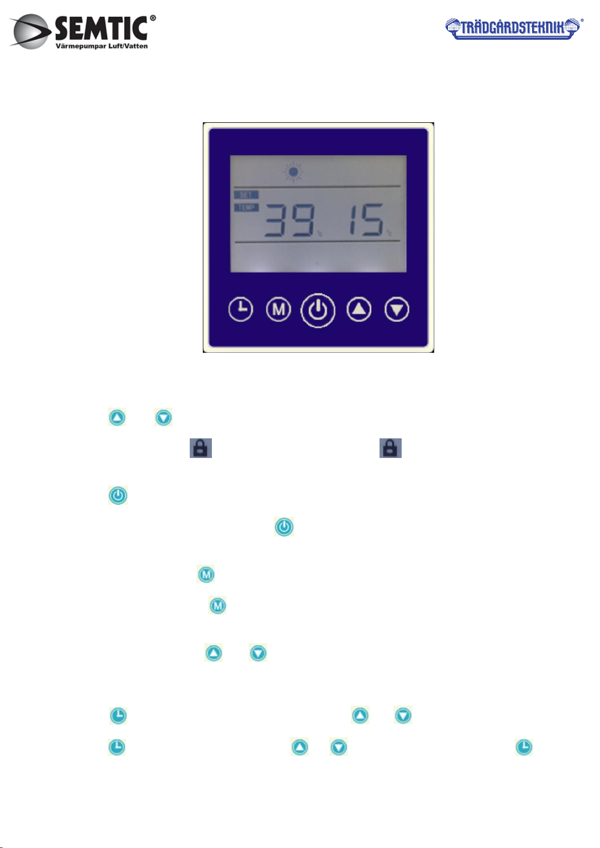
1. Indoor line control panel (BKDX30-95)
2. Button Instruction
2.1 Button lock and unlock
Press and to lock or unlock the controller.
When in lock status,the display ,when in unlock status,the hide.
2.2 On/off Button
Press to switch on/off the unit.
In power on status,in heating mode,press for 3 seconds then forced into defrost process.
2.3 Mode Button
In switch on status,press to select the working model.
In switch off status,press to for 3 seconds to forced into recycle refrigerant function.
2.4 Temperature Setting
In switch on status,press or to set the temperature,press more than 0.5 second to fast
increase or decrease.
2.5 Clock setting
Press for 3 seconds,minute number flashes,press or to modify the minute number.
Press again,hour number flashes,press or to modify the hour number. Press again
16
to save and exit the clock setting.
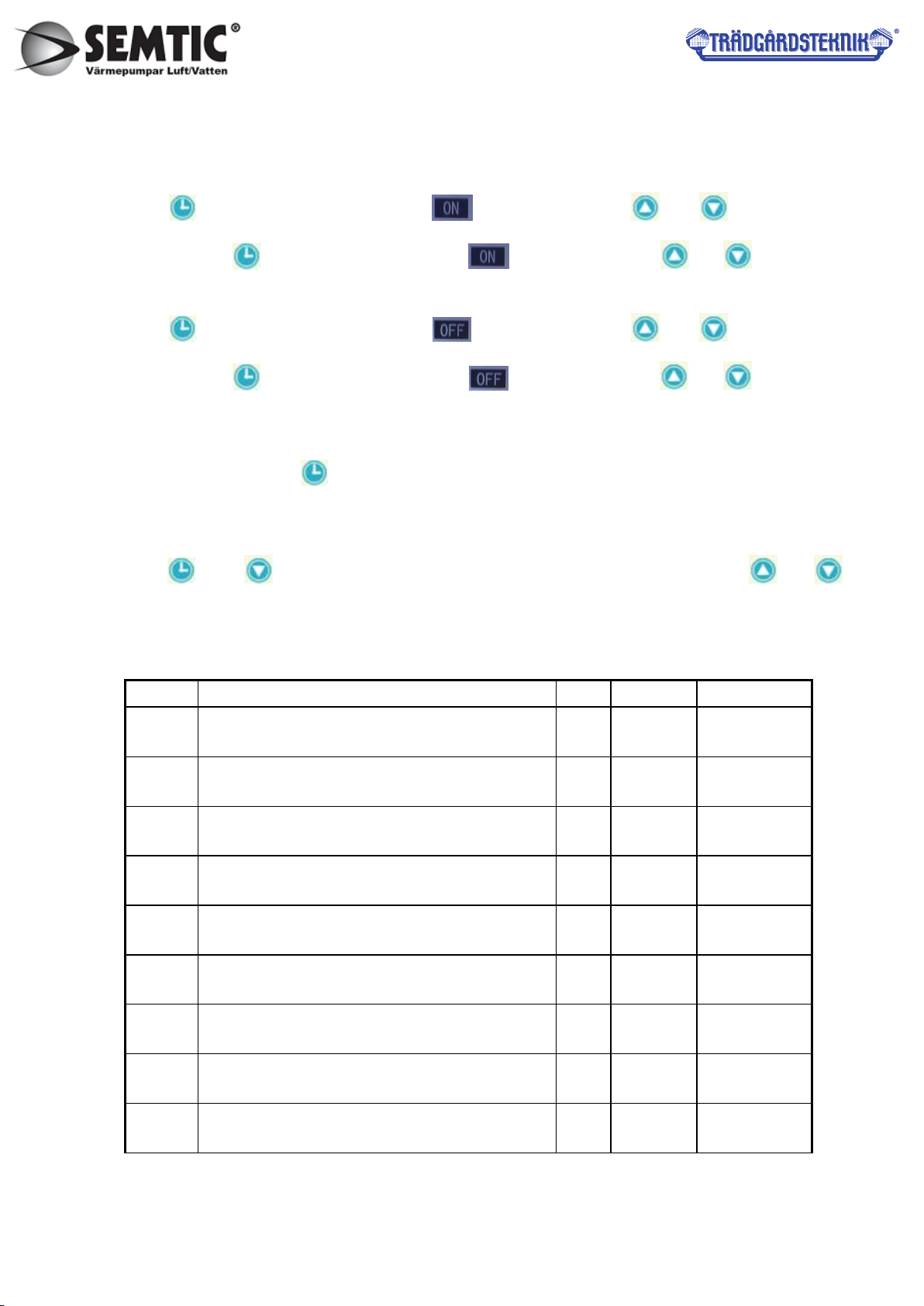
2.6 Timer Setting
Press ,minute number flashes and icon flashes,press or to modify minute
number. Press ,hour number flashes and icon flashes,press or to modify hour
number.
Press ,minute number flashes and icon flashes,press or to modify minute
number. Press ,hour number flashes and icon flashes,press or to modify hour
number.
Without operation in 10 seconds then exit timer setting.
After timer setting, press again to cancel the timer .
2.7 Parameters Checking
Press and for 3 seconds to enter into parameters checking status,touch or to
check each parameter.
Parameters table
No. Status name Unit Ranger Remark
d01 Inverter compressor current actual frequency Hz 0~150
d02 Inverter compressor operation(input) current A0~50.0
d03 Water return temperature ℃-30~999
d04 Water tank temperature ℃-30~999
d05 Water supply pipe temperature ℃-30~999
d06 Reserve ℃-30~999
d07 Exhaust gas temperature ℃-15~999
d08 Ambient temperature ℃-30~999
d09 Evaporator coil temperature ℃-30~999

17
Button instruction
Fault code and instruction table
Code No. Fault Name
E01 Outdoor unit current protection
E02 Flow switch protection
E03 EEPROM error indication (indoor board) / EEPROM error indication (operation
panel)
E04 Return water temperature over high when heating or output water temperature
over low when cooling
E05 DC link voltage is over high / low protection
E06 IPM failure
E08 Output and input water temperature different too large protection
E09 Communication error ( indoor board and outdoor board)
E10 Return water temp sensor fault
E11 Output water temp sensor fault
E12 Tank temp sensor fault
E13 Ambient temp sensor fault
E14 Evaporator temp sensor fault
E18 Compressor outlet gas temp sensor fault
E21 Compressor outlet gas temperature over high
E25 Evaporator coil temperature too high when cooling model
E31 System pressure over high protection
E32 Communication error (operation panel & indoor board)
E33 Communication error (IPM & outdoor board)
d10 Gas return temperature ℃-30~999
d11 After throttling temperature ℃-30~999
d12 Opening of EXV(shown as the actual opening ) P0~500 Pulse count

18
E41 System pressure over low protection
E44 Winter unit standby antifreeze protection
E45 Return gas temp sensor fault
E46 Temp sensor fault after throttle
E47 Water tank temperature sensor abnormal protection
E48 Antifreeze switch disconnect failure
BKDX50-200, BKDX80-280
2.21. Operation illustration & displays
Symbol Definition Symbol Definition
On/Off Key Hot Water Mode Botton
Timing Setting Key Room Heating Mode
Botton
Add Botton Cooling Function Mode
Botton
Subtract Botton Defrosting Function
Botton
Mode Botton Timing Botton
2.3.1 Wired Controller Display Declaration
2.3.1.1 Temperature display area display system cock, timing, running parameters, common
parameters, alarm code related datas.Left side temperature display area display actual detect tank
temperature ,setting temperature ,parameter number etc.
Right side temperature display area display setting temperature ,parameters values etc.
2.3.1.2 Flashes of the various fields show the flashing period for 1 second; after the full power of about
3 seconds after the normal operation.

19
2.3.1.3 30 seconds without key operation, the LCD display brightness will automatically extinguished.
2.3.2 Wired Controller Operation
2.3.2.1 On/ Off Key: when heat pump shutdown, press “ ” to start up the unit ; when heat pump start
up press “ ”key to shutdown the unit. When heat pump under heating start up status, press “ ” for
more than 3s to force unit to enter defrosting function .
2.3.2.2 Mode Key: When the wired controller is on, Press“ ”to choose the operating mode, and also
for setting temperature, checking & setting parameters, etc.
2.3.2.3 Temperature Setting: When the wired controller is on, press“ ”or“ ”,the temperature
data on the screen will show up, then press “ ”or“ ”to add or reduce,
then press“ ” to confirm the
modifying, or after 20 seconds without any operation, it will automatically quit from the temperature
setting, and store the current modified data, press“ ” or “ ” without stop for over 0.5 second to start
quick adding or substracting.
2.3.2.4 Key locked function: First press “ ”, then press “ ” for 3s to enter or exit key locked
function, when “ ”symbol show up means wired controller locked.
2.3.2.5 Inquiry running parameters
2.3.5.1 Enter inquiry: first press “ ”then press “ ” for 3 s to enter parameters setting status,
temperature display area display parameter number, setting temperature area display parameters
content.
2.3.5.2 Inquiry operation and exit: after entering running parameters, press “ ”or “ ”to display
each running parameter; press “ ”to exit inquiring parameters status or if there is not any pressing
keys operation will automatically exit inquiring parameters status after 20s.
2.3.2.6 Common parameters setting
1.3.6.1 Enter setting ; first pressing “ ” then press “ ” for 3 secs,the temperature display area
display “00” and blinking display ,input the password (default password “Fb”),then press “ ”or “ ”to
add or subtract ,press “ ”or “ ” to confirm ,if the password is wrong then exit current status ; if the
password is correct then enter parameter modification status ,temperature display area display
parameters number and blinking display ,setting temperature area display parameter content ;

20
1.3.6.2 Setting operation : after entering setting parameters, the parameter number blinking
display ,press “ ”or “ ”switch line to display each setting parameters number ,then press “ ”the
parameters content blinking display ,press “ ”or “ ” to modify current content ,after finishing press
“ ” to save current modification then back to parameters number display status .
1.3.6.3 Exit setting; press “ ”to exit parameters setting status or if there is not any pressing keys
operation will automatically exit parameters setting status after 20s.
2.3.2.7 Fault display; when unit fault occurs, the fault blinking display at setting temperature area,
recycling display fault code and temperature, after fault clear the controller recover normal display.
2.3.2.8
2.3.8.1 Clock display: in unit shutdown status, long press any keys except “ ”, the temperature
display area display current time for one second.
2.3.8.2 Enter clock setting; long press “ ” for 3 secs.minutes part of clock area blinking display,
means entering clock setting status
2.3.8.3 Clock setting operation : enter clock setting status ,minutes part blinking display ,press “ ”or
“ ”to modify minute value .Then press “ ”,hours part blinking display ,press “ ”or “ ”to
modify hour value ,press “ ” to save current setting then exit or if there is not any pressing keys
operation will automatically save current setting then exit.
2.3.2.9 Setting Timing Control
2.3.9.1 There are 2 group timing units, 1 ~2 group ,each timing unit group can set as “timing
startup ”timing shutdown. Default setting is “invalid”, means timing startup and timing timing shutdown is
same.
2.3.2.9.2 Enter the setting timing: short press “ ”,symbol “1 ”、“ON ”at left bottom screen blinking
display ,minutes display area blinking means enter “1 unit timing startup ”setting status ,the minute
position blinking display ,press “ ”or “ ”to modify minute value ,then press “ ” to confirm then
enter hour setting ,the hour position blinking display , press “ ”or “ ”to modify hour value ,press
This manual suits for next models
3
Table of contents
Other Semtic Heat Pump manuals


Popular Heat Pump manuals by other brands

Panasonic
Panasonic WH-UD09HE5 operating instructions

Mitsubishi Electric
Mitsubishi Electric SLZ Series Technical & service manual

NorAire
NorAire NC-FE series Installation & operating instructions

York
York AFFINITY YZH02411 Technical guide

Trane
Trane 4WCC4036E1000B Installation and operation manual

Trane
Trane 4TWR7 Installer's guide


Panasonic
Panasonic S-80MW1E5 Installation instructions manual

Dimplex
Dimplex SIK 8 TES Installation and operating instructions

Danfoss
Danfoss DHP-iQ installation guide

CLIVET
CLIVET WSAR-MT Series Installation and use manual

ThermoTec
ThermoTec 29kw Installation instructions manual

Daikin
Daikin DP5HM installation instructions