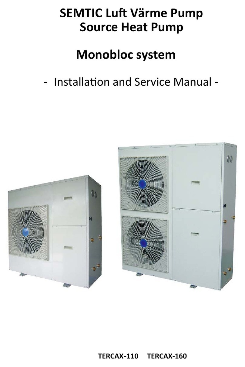
Semtic NERS-B3Y Owner's manual

SWIMMING POOL HEAT PUMP

Contents
I. Security and prevention----------------------------------
1. Notice---------------------------------------------------------------------------
2. Warning -----------------------------------------------------------------------
II. Advantage ----------------------------------------------------
--------------------------------------------------------------1. Compressor-----
2 --------------------------------------------------------. Digital controller-----
3-----------------------------------
Heat exchanger-----
4 --------------------------------------------------. Heat&cool capability-----
5 --------------------------------------------------------. Hot gas defrost-----
III. Specification -------------------------------------------------
1. Model Nomenclature-------------------------------------------------------
2. Parameter --------------------------------------------------------------------
3. The installation dimensions-----------------------------------------------
IV. Installation-----------------------------------------------------
1. Positioning you swimming pool heat pump---------------------------
2. Unit installation position----------------------------------------------------
3. Installation requirement ----------------------------------------------------
4 --------------------------. Connecting your swimming pool pipe work
5. Installation drawing ---------------------------------------------------------
6. Electric wiring ---------------------------------------------------------------
7 -----------------------------------------------. Selection of electrical wire
V. Use ---------------------------------------------------------------
1. Wire controller device installation----------------------------------------
2. Uses of the remote controller----------------------------------------------
I. Maintenance -------------------------------------------------V
1. Note ---------------------------------------------------------------------------
2 --------------------. Malfunction indicating table--------------------------
3. Determine and solve malfunction by below table-------------------
VII. Wiring diagram---------------------------------------------
1. NET92033 PCB input and output port definition--------------------
2. Power phase sequence protection board setting--------------------
3. The internal structure in electrical box----------------------------------
4 ---------------------------------------. Wiring diagram------------------------
1
1
1
1
1
2
2
2
2
3
3
3
4
6
6
6
7
7
8
8
9
10
10
10
12
12
12
13
15
15
16
17
22

I. Security and prevention
1.Notice
1.1 In order to use this product better and safer, please read this instruction carefully before install
and operate it. Please pay attention to all the notice in operation and maintenance. Save all manuals
and documentation for future reference.
1.2 Swimming pool heat pump is a special appliance. Improper installation will cause damage and
danger. It should be installed and maintained by the professionals. Please contact our authorized local
service point for installation and maintenance. Please read and follow this instruction carefully before
and during installation.
Remarks:
We will not bear the responsibility for any personal injury or unit damage caused by non-Compliance
of the regulations and instruction in this manual.
1.3 Please check whether the distribution power capacity, switch and socket are compliance with the
requirements of our unit power. Details please refer to the rating label or parameter table in this
manual.
1.4 The power should be equipped with leakage protection separately. Power cable should be chosen
in accordance with the operation requirements of the unit.
1.5 The unit must be grounded safely. Do not use the unit if grounded unsafely. Do not connect the
ground line to the neutral and or tap water pipe.
1.6 The wire must be joined in compliance with the requirements of the wiring chart. Do not alternate
and or repair the unit personally.
1.7 Do not install the unit closed to inflammable, explosive and naked light spot.
1.8 To ensure the unit operate properly, please equipped with a filter in the water input when
installation.
1.9 Please contact us or our authorized service site if the unit failures. The unit can’t be used again
without technicians’ checking.
1.10 The unit parameter has been set before leave of the factory. The parameter Can’t be adjusted
by the unprofessional.
1. Scroll Compressor
II. Advantage
2.Warning!
2.1 Do not carry devices alone.
2.2 Connect all the ground wires.
2.3 All the electrical connections should be made by a certified electrician .
2.4 When manipulating electrical equipment, make sure there is no voltage using a well calibrated
voltmeter . To avoid damaging the equipment the equipment, do not use heating or cooling devices
during the construction phase. Why? Because components can become obstructed with dirt and
debris which man damage the device.
50% fewer moving parts than standard piston-type compressors. This equates to much
improved reliability and improved efficiency. Scroll compressors are also much quieter in
operation than their piston-type counterparts. And, while all heat pumps are known for the
ir low operating noise levels.
1

2
2. Digital Controller
Digitally-based microprocessor controls water temperature to within 1℃
of set point.
Controller also permits user to predefine different pool and spa water temperatures, and to
prevent tampering by locking out controls via a
control ke
.y
3. Heat Exchanger
The heart of your heat pump is the patented
heat exchanger. One of the
primary causes of
premature heat pump demise is the failure of the heat exchanger. Ordinaryheat exchangers
are made from a cupronickel alloy
and the shell is made by PVC.
This
cupronickelmaterial is susceptible to attack from the sanitizers used in pools and spas and
from other related water chemistry conditions. Once the heat exchanger fails, the heat pumpis
ruined.And
The PVC is can't bear too high pressure and temperature, and exit the risk ofburst
and leak.
The
heat exchanger tube is made from titanium, and isvirtually impervious to water
chemistry damage,
and the shell is made form a patent
secret
ingredients, it can standmore than 21kg water pressure and high temperature.
4. Heat&Cool Capability
Puts you in full control, year round... Warms your pool or spa with the reliability and efficiency
of our other heat pumps, but, with the flip of a switch, can also cool your pool or spa to
refreshing temperatures during hot summer months. For cooler climates, Heat & Cool heat
pumps offer unique advantages over passive defrost models. Please read more below...
5. Hot Gas Defrost
Hot gas defrost heat pumps are uniquely equipped for an
active
defrost cycle.
Active defrost
involves directing hot refrigerant vapor to the heat collector, melting accumulated ice away in
a matter of a few minutes... then right back to heating. Standard defrost heat pumps may
remain
“off in defrost”
for extended periods during very cold weather. Because of their
ability to continue to operate-even during freezing weather-hot gas defrost models extend the
swimming season longer than
any
standard-defrost heat pump.
PLEASE READ FURTHER
TO BECOME FAMILIAR WITH
ALL
THE FEATURES,
THE SAFE
OPERATION

2.Performance of Swimming Pool Heat Pump
3
III. Specification
NERS-G8Y
34.5
23.5
6.65
380V/3PH/50Hz
28
40
14.8
IPX4
Ⅰ
60
≤60
1360*854*1320
260
272
4.2/4.2/4.2
Model
Rated heating capacity
Rated cooling capacity
Rated input power
Power supply
Rated output water temperature
Max output water temperature
Rated circulating water flow
Refrigerant
Rated of waterproof
Rated of Elc.leakage protection
Pressure drop between inlet
and outlet water
Noise
Max Heat exchanger's pressure
Net Dimendions (L/W/H)
Net Weight
Gross Weight
KW
KW
KW
V/PH/Hz
℃
℃
3
m /h
IPX4
kPa
dB(A)
MPa
mm
kg
kg
NERS-B6Y
26.2
18.3
5.12
380V/3PH/50Hz
28
40
13
IPX4
Ⅰ
40
≤58
165
175
4.2/4.2/4.2
NERS-B5Y
22.5
15.7
4.24
380V/3PH/50Hz
28
40
8.7
IPX4
Ⅰ
40
≤55
1108*518*1257
155
162
4.2/4.2/4.2
NERS-B3Y
12.8
8.96
2.43
28
40
5
IPX4
Ⅰ
30
≤50
1108*518*904
100
105
4.2/4.2/4.2
220V/1PH/50Hz
COP
W/W
5.19
5.125.35.27
Inlet/outlet size
Compressor
R410A R410A R410A R410A
Class
1.5" 1.5" 1.5" 1.5"
Copeland Copeland Copeland Copeland
1108*518*1257
NERS-G30Y
120
91
23.5
380V/3PH/50Hz
28
40
52.5
IPX4
Ⅰ
70
≤66
2180*1000*1980
800
840
4.2/4.2/4.2
Model
Rated heating capacity
Rated cooling capacity
Rated input power
Power supply
Rated output water temperature
Max output water temperature
Rated circulating water flow
Refrigerant
Rated of waterproof
Rated of Elc.leakage protection
Pressure drop between inlet
and outlet water
Noise
Max Heat exchanger's pressure
Net Dimendions (L/W/H)
Net Weight
Gross Weight
KW
KW
KW
V/PH/Hz
℃
℃
3
m /h
IPX4
kPa
dB(A)
MPa
mm
kg
kg
NERS-G24Y
101
74.2
19.6
380V/3PH/50Hz
28
40
40.0
IPX4
Ⅰ
70
≤64.8
750
775
4.2/4.2/4.2
NERS-G12Y
53.2
37.2
10.2
380V/3PH/50Hz
28
40
20.8
IPX4
Ⅰ
60
≤60
320
340
4.2/4.2/4.2
NERS-G10Y
45
30
8.65
28
40
17.5
IPX4
Ⅰ
60
≤60
1360*854*1320
300
315
4.2/4.2/4.2
COP
W/W
5.11
5.155.225.20
Inlet/outlet size
Compressor
R410A R410A R410A R410A
Class
1.5" 1.5" 3.0" 3.0"
Copeland Copeland Copeland Copeland
2180*1000*1980
380V/3PH/50Hz
1360*854*1320
Heating:the specifications are based on DB Temperature 24C,WB Temperature 19C,Water in/out 26C/28C.
Cooling:the specifications are based on DB Temperature 35C,WB Temperature 32C,Water in/out 30C/28C.

3. The installation dimensions
4
886
903.6
1105
452
430
1108
1134.5
518
489
3.1 NERS-G3Y
3.2 NERS-G5Y, NERSG6Y
1257
1222

5
1312
1626
854
2180
1000
1980
3.3 NERS-G8Y, NERSG10Y,NERS-G12Y
3.4 NERS-G24Y, NERS-G30Y

1. Positioning Your Swimming Pool Heat Pump
1.1 For correct operation air must be free to circulate around the heat pump. Do not place the
unit in a shed, greenhouse or similar. This unit is designed to be placed outdoors only.
1.2 Refer to the drawing below for required clearance.
1.3 You should position the heat pump so that the control panel does not face directly towards
the sun.
1.4 The heat pump must be upright.
1.5 The distance between the heat pump and the pool / plant room should be as short as
practically possible to reduce pressure and heat loss in the pipe work.
1.6 Insulating the pipe work will assist with the prevention of heat losses.
1.7 An isolator switch should be installed (by a qualified electrician) near the heat pump.
1.8 The electrical supply to the heat pump must be protected by a 30mA RCD.
1.9 The air inlets and outlets must not be obstructed or blocked.
1.10 Even though the heat pump is low noise, it must be positioned so as to be considerate
to neighbours.
1.11 Your heat pump must be placed on a solid base.
1.12 Avoid the condensation will drip from underneath the heat pump, the base must be able
to tolerate this.
IV. Installation
2. Unit installation position
To avoid ventilation short, the r unit discharged air should not return when installation.
Please keep enough space around the unit for repair. Right and wrong means as below:
Wrong Right
!
NOTICE:
1. To get enough air for ventilation of the unit, the installation position should be with good
ventilation.
2. The installation position can hold the outdoor unit without noise and shake.
3. No sunlight to the unit. Set an awning if necessary.
4. The water from rain and defrosting can be discharged in the installation position.
5. The unit will not be covered by snow in the installation position.
6. The discharged air will not face strong air in the installation position.
7. Assure the noise caused by the unit ventilation and operation will not affect the
neighbour.
8. The installation position will not be affected by garbage, oil and mist.
9. The unit will be damaged under the condition with oil(engine oil), salt(sea area) and
sulfide air(near thermal spring and refining factory).
6

3. Installation requirement
3.1 The unit can be installed in the balcony, roof, floor or any other convenient place and reliable
load-bearing.
3.2 Airiness place.
3.3 No heat radiation or other heat source place
3.4 Should be set up shed against the snow in winter.
3.5 Barrier-free at the air inlet or outlet place.
3.6 Outlet against strong winds blowing place.
3.7 There should be drainage channels around the machine in order to rule out the condensate.
3.8 Control Panel, do not install in the bathroom, so as not to affect the unit work by wet.
3.9 Should leave enough space around the machine. As shown below.
4. Connecting Your Swimming Pool Pipe Work
4.1 The pool water is fed through the heat pump by a swimming pool pump.
4.2 The heat pump must be installed after (down stream) the swimming pool filter so clean,
filtered water passes through it.
4.3 Double union ball valves must be fitted just before the heat pump inlet and just after the
outlet to aid servicing and winterising.
4.4 Each heat pump has a maximum water flow rate. If the flow via the pool pump is higher
than this then a by-pass should be installed. Consult your supplying dealer.
4.5 Each heat pump also has a minimum flow rate, below this the heat pump will not operate.
Consult your supplying dealer.
4.6 Pipe work of less than 1-1/2” diameter should not be used.
4.7 Fit a union nut onto each pipe.
4.8 Push the gasket over the pipe until the gasket is about 5 -10mm from the edge of the pipe.
You may need to lubricate the gasket.
4.9 Insert the pipe into the heat pump and tighten the union nut.
4.10 The union must only be hand tightened.
≥700mm
≥400mm
≥600mm
≥1000mm
≥700mm
≥400mm
≥400mm
≥1000mm
≥2000mm
Bolt
fix
4.11 If the swimming pool is equipped with a chlorinator, brominator, or possibly chemical
control with acid and chlorine pumps, these must be in the return pipe work after the heat
pump and a non-return valve used. Any dosing system must be the final equipment before
the water returns to the swimming pool. Damage caused to the heat pump by chemical dosing
units is not covered by warranty.
4.12 Any heat exchanger or electric heater fitted as auxiliary heating must be installed after
(down stream from) the heat pump so as to avoid pre-heating the pool water before it enters
the heat pump.
7

5.Installation Drawing
6.1 Unit supply cable must be used copper. Power supply voltage in line with theshould be
rated voltage and the rated current.
6.2 The unit, power supply circuit must have a grounding wire, and the power supply ground
wire must with the external grounding wire, and an external grounding wire to beconnect to
effective.
6.3 W must be installed by professional technicians carried out in accordance iring installation
with circuit.
6.4 S up a good leakage protection devices etting and in accordance with the relevant national
technical standards.
6.5 Power line and signal line layout should be neat, rational, strong and weak lines separating
cable and Can not interfere with each other, without contact with the connecting pipe and valve.
6.6 he construction of all wiring is completed, carefully check the correct order to connect After t
the power.
6.7 Unit electric wire connection: connect to the appropriate terminals according to wiring
diagram, and fix it by the pressure line of board in the electrical box.
6.8 All the wiring construction is completed, can be plugged in only after careful examination
correctly.
6.9 Unit control board fuse parameters: 3.15A.
6. Electric wiring
Unit electric box
(380V/3ph/50Hz)
PCB
Power input
(380VAC/3PH/50Hz)
R S T N
Wire controller
6. 10 lectric wiring installation drawingUnit's e
L1 L2 L3
Connect to the swimming
pool side water pump
(380VAC/3PH/50Hz)
CN9
ROO M
SET
MAUX
8
Water cycle pump

7. Selection of Electrical Wire
7.3 Caution of Ground The internal motor protector does not protect the compressor against
all possible conditions Please be sure that the system utilizes the ground connection when
installed in the field.
7.1 Voltage drop may occur due to the large current draw during compressor starting, and
may be result in the compressor is difficult to stat. So we recommend selecting the wire
specification from the table below.
7.2 Specification Table of Electrical Wire
7.4 Warning: To avoid fire, electric shock and other accidents, keep in mind about these tips:
A: Only use power supply voltage indicated on the label, if you do not know the family of
voltage, contact the dealer or local power company.
B: When you use the unit by the maximum current please view the specifications, so make
sure our home's power supply (current, voltage and cable) to meet the machine's normal load
requirements.
Host PowerMode: Phase line Zero line Ground line Circuit break
C: To protect the power lines. Power lines should be fixed, so that people will not be trip over
or the lines damaged by other things. Paying particular attention to plugs, which should be
easily plug into the socket, careful the plug position.
D: Do not overload wall plugs or extension the cable. Line overload can cause fire or electric
shock.
E: To ensure your safety, you must plug the power lines into the socket with a grounded
three-phase, and check to ensure your socket is accurate and reliable grounding.
9
NERS-G12Y
380V/3PH/50Hz 2
6.0mm 2
4.0mm Capacity:40A specification: <30mA <0.1sec
2
6.0mm
NERS-G24Y
380V/3PH/50Hz 2
10.0mm 2
6.0mm Capacity:80A specification: <30mA <0.1sec
2
10.0mm
Unit electric box
(220V/1ph/50Hz)
PCB
Power input
(220VAC/1PH/50Hz)
Wire controller
L N PE
Connect to the swimming
pool side water pump
(220VAC/1PH/50Hz)
CN9
ROO M
SET
MAUX
L N PE
NERS-G4Y/G3Y
220V/1PH/50Hz 2
6.0mm 2
4.0mm Capacity:21A specification: <30mA <0.1sec
2
6.0mm
NERS-G6Y
380V/3PH/50Hz 2
4.0mm 2
2.5mm Capacity:18A specification: <30mA <0.1sec
2
4.0mm

V. Use
1.Wire controller device installation
2.Use of wire controller
The remote controller is designed and employed standard electrical box dimensions
(86*86,fixed hole distance 60mm). The electrical box and three core can be built in the
wall before decoration, which makes the interior decoration more perfect. The
illustration shows as below:
Cover the face covering in the reverse procedures
as shown in Illustration 2 and Illustration 1 to
complete the mounting of the remote controller.
Put the remote controller in the electrician base .
box and tighten the two setscrews.
Illustration 3
Illustration 4
Illustration 1
Illustration 2
Use flat screwdriver to press down the two back-off
and lift open the face covering.
Remove the top covering leftwards to disengage
two top back-off.
2.1 The user interface and function shows as below:
10
I N
R O O M
SET
M
A B CD E
G
F
H
I
R
Q
P
O N M L K J
NO. Symbol Means
A
B
Automatic mode icon
Cooling mode icon
C
D
E
F
G
Water outlet temp. icon
Ambient temp. icon
Auxiliary electric heater icon
Temperature display area
R O O M
H
I
J
K
L
M
M
Timer on icon
Timer off icon
Timer /auxiliary electric heater
button setting
Clock setting button
O
P
Q
R
Down setting button
Up setting button
Model select setting button
Unit turn on/off button
Time and parameter display area
Button lock icon
Inlet temperature icon
I N
SET
M
SET
OUT
AUX
O U T
Heating mode icon
N
AUX
T E M P
N O.
S
T
T
S
The number of parameter
The icon of measure temperature
N O.
T E M P
1
2
U
V
U
V
The first period of timer icon
1
2
The secondperiod of timer icon

11
2.2 Turn on/off the unit.
Press“ ” button to turn on turn off the unit. When the unit is under the turn off status.
The interface display the mode icon, and the ambient temperature,like the picture 1.when the
unit is under the turn on status,the interface display the mode icon, the inlet and outlet
temperature,like the picture 2.
2.3 Mode selection.
Press“ ” this button to choose “ ”cooling and heating mode “ ”cooling
mode or “ ” heating mode.
2.5 Clock setting.
Press “ ” button for 5 second, and the bit hour is flicking, press “ ”to adjust
the setting of hour.Press “ ” button again. the bit minute is flicking. Press“ ”
buttons to adjust the setting of minute. Press “ ” button again to complete and exit the
clock setting mode.
2.4 Water inlet temp. Setting.
On standby or power on status, press“ ”button,enter the parameter setting interface.
Press the“ ” button to adjust the setting of water inlet temp.
(The parameter of “ 00 ” is cooing mode setting temperature,the parameter of “ 01 ” is
heating mode setting temperature.).
R O O M
SET
MAUX
picture 1 picture 2
I N
SET
M
OUT
AUX
M
SET
SET
SET
SET
2.6 Unit turn on /turn off timer setting.
Press “ ” button for 5 second, the of place hour, minutes and timing 1 ON symbol
keep display. And the place of hour keep flicking, then, press the button of “ ”
to adjust the setting of the hour. Press“ ”button again, and the bit minute flicks. Press
“ ”buttons to adjust the setting of minute; Press“ ”button again and the
place of hour and timing 1 OFF symbol display. And the place of hour keep flicking, press
“ ”button to adjust the setting of hour. Press“ ”button again, and the bit
minute flickers. Press“ ”buttons to adjust the setting of minute. Press“ ”
button again,the of place hour, minutes and timing 2 ON symbol keep display, the second
period of timer setting like the first period timer setting, when you finish the timer setting,press
Press“ ”button complete the timer setting and exit the timer setting interface.
(Note:if you want to cancel the timer,setting the time on is 00:00 and the time off is 00:00 too )
AUX
AUX
AUX
AUX
AUX
AUX
2.7 Button Lock.
Press“ ”and“ ”button at the same time for 5s, symbol“ ”comes out, it
means all buttons on the display are locked, but it can be unlocked after pressing both
“ ”and“ ”button at the same time for 5s again.
(B3Y don't have this function)
(B3Y don't have this function)

10) These settings are for Engineers only, please call if you require to change any of the Optional
Parameters.
Under the standby status, press “ ”button enter system parameter checking and setting interface.
Press“ ”button to select the parameter you need, if you want adjust the parameter data,press
“ ”and“ ”button and the same time for 5second,until you hear the sound of “ B ”,
press“ ”or“ ”button to set data you need. Parameter table as below:
Note:1 The parameter of “ 00 ”and “ 01”is user parameter.
Note:2 The controller esc automatic after staying status 8 seconds.
2.8.The checking of status parameter
Press the“ ”or“ ” button enter the running state parameter checking interface
Esc automatic after staying status 8 seconds.
.Symbol Means
Temp. icon
Inlet water temperature
Outlet water temperature
T E M P
I N
O U T
Ambient temperature
System 1 coil temperature
R O O M
P1
P2 System 2 coil temperature
2.9.The system parameter setting.
SET
SET
Water inlet temp. Setting
(cooling mode)
00
01
02
03
04
05
06
07
08
09
10
Digit meaning range default Adjust
Water inlet temp. Setting
(heating mode)
Defrost cycle
The temp. setting to enter defrost status
The temp. setting to exit defrost status
Defrosting time
The system number setting
1:single system.2:double system
Power lost memory
0:without 1: with
Unit Model selection
Working mode of water pump
Adjusted by technicians
Adjust
Adjust
Adjusted by technicians
Adjusted by technicians
Adjusted by technicians
Adjusted by technicians
Adjusted by technicians
Adjusted by technicians
Adjusted by technicians
Adjusted by technicians
8~28℃
15~40℃
30~90MIN
-30~0℃
2~30℃
1~12MIN
1 / 2
0 / 1
0~3
0~1
2~20℃
28℃
28℃
40 MIN
-3℃
13 ℃
8 MIN
2
1
1
0
2℃
Remarks: parameter 08
0:cooling
1:cooling&heating
2:auxiliary electric heating + heat pump (Auto mode can be selected)
3:heating +auxiliary electric heating
parameter: 09
0:always working
1:water pump starts working for 1 min before the compressor starts to work,
water pump stop working after the compressor stop working for 30 secretary.
The difference setting for compressor
restart running
12

1.6 Care the unit if the unit stops for a long time. Discharge all the water in the pump and
throughout the pipe route in case breakdown to the water pump and pipe caused by frost and
freeze. Discharge the water from the water pump and tube exchange Button drain. Check the
unit thoroughly and flood water into the system before the unit power on again.
It, the operation pressure of the refrigerant system.
1.7 To check the power supply and cable connection often, there is abnormal action or bad
smell about the electrical component. If there is, please maintain or change it in time.
2.Malfunction indicating table
VI. Maintenance
1.Note
1.1 Check whether the exhaust equipment is normal. Avoid cutting of the water supply and or
air entering into the system, or it will influence the performance and reliability of the unit. The
water filter should be cleaned regularly. Keep the water clean in case of any damage to the
unit due to filter's dirty and jam.
1.2 Keep the unit environment dry, clean and well ventilation. Clean the side air exchanger
regularly(once per1-2 months) in order to maintain high exchange efficiency and save energy.
1.3 Often check the performance of all the parts in the unit. Check whether the working
pressure of the refrigerant system is normal. Repair and change the parts timely if there's any
abnormity .
1.4 Often check whether the wiring of the power and electric system is tightened and or
electric parts perform abnormally or smells. Repair and change the parts timely if there's any
abnormity.
1.5 To check the operation of every process in the unit, the operation pressure of the
refrigerant system.You should maintain or change it in time.
Check or change the sensor
Temp is too much different
between water-in and
water-out for cooing mode
Swimming pool side water
inlet temp. Sensor failure
The swimming pool side
antifreezing protection
under cooling mode
Check the water flow volume,
or water system is jammed or not
Check the water flow volume,
or water system is jammed or not
The sensor is open or short circuit
Not enough water flow volume &
water pressure difference is too
low for swimming pool side
Swimming pool side water flow
volume is not enough
Malfunction
Reason Resolution
Wire
Controller
PP 01
PP 06
PP 07
Check or change the sensor
Check or change the sensor
Check or change the sensor
Check or change the sensor
Swimming pool side water
outlet temp. Sensor failure
System 1 coil temp.
Sensor failure
Ambient temp. Sensor failure
The sensor is open or short circuit
The sensor is open or short circuit
The sensor is open or short circuit
The sensor is open or short circuit
PP 02
PP 03
PP 04
PP 05
13
System 2 coil temp.
Sensor failure

PP 07
The system recover automatically
after running antifreeze process.
The ambient temp.and the water
outlet temp. is too low under
standby status.
The swimming pool side
automatic antifreezing
protection in winter
Malfunction of system 1
low pressure protection
3 times of excessive temp.
Differentials of inlet water
and outlet water in 30 minutes
EE 02
EE 05
System 1 low pressure switch
protection
No water/little water flow
volume too small in water
system.
Water flow volume not
enough, water pressure
difference is too low
Check whether the pressure
switch and refrigerant is miss
or not.
Check the water flow volume,
water pump is failure or not.
Check the water flow volume,
or water system is jammed
or not.
Phase lack or phase
sequence error of power
supply
Phase lack or phase error
of power supply(only for three
phase unit)
Check power supply(only for
three phase unit)
EE 01
System 1 high pressure
switch protection
Check whether the pressure
switch and water cycle system.
Malfunction of system 1
high pressure protection
Wire controller and The
PCB connection failure.
Communication failure EE 08 Check the wire connection
Swimming pool side water
flow switch failure
EE 03
EE 04
EE 06
EE 07
3.Determine and solve malfunction by below table:
The unit can't run
1.Check the water supplement equipment and
supply water into the system.
2.Discharge the air from the water system
3.Clean the water filter or exhaust the air from
system
1. The water system is lack of water
2. There's air in the system.
3. The water system valve doesn't open
entirely
4. The water filter is dirty and jam
The water pump can run but
can't circulate and is noisy
The heating capacity is too
low and the compressor works
continuously without pause.
1.Check the leakage and add refrigerant.
2.Enhance the thermal insulation of the pipe
route.
3.Clean the exchanger and improve the
condensation condition.
4. Clean the water filter.
1. Refrigerant is insufficient.
2. Thermal insulation of the water system
is poor.
3. Thermal discharge of the exchange is
poor.
4. Water flow volume is insufficient.
1. Shut down and check the power
2.Check the reason and repair
3.Check and change the power fuse
1. Power failures
2. The unit wire loses
3. The unit power fuse burns out.
Malfunction Reason Solution
14
System 2 high pressure
switch protection
Check whether the pressure
switch and water cycle system.
Malfunction of system 2
high pressure protection
Malfunction of system 2
low pressure protection
System 2 low pressure switch
protection
Check whether the pressure
switch and refrigerant is miss
or not.
1. Discharge surplus refrigerant
2. Clean the exchanger and improve the
condensation condition
1.Too much refrigerant
2.Thermal discharge of the exchange
is poor
1.Check the reason and solve the malfunction.
2.Change the compressor.
1.Refrigerant enter into the compressor.
2.Compressor damaged.
Compressor noisy.
The compressor exhausted
pressure is too high
1.Check the leakage and add refrigerant.
2.Change the capillary tube or filter.
3.Clean the exchanger and improve the
condensation condition.
4.Change the expansion valve.
1. Refrigerant is insufficient.
2. The filter and or capillary tube jam.
3. Water flow volume is insufficient.
4. Capillary tube of expansion valve
sensor bulb breakdown.
The compressor suction
pressure is too low.

15
1.Check the leakage and add refrigerant
2.Check the reason and change the plate
exchanger.
3.Change the compressor.
1. The refrigerant leak out
2. Plate exchanger freezes
3. Compressor failure
The compressor run but no
refrigeration.
1.Clean the water filter and exhaust the air
from the system.
2.Change the flow switch.
Few water flow volume
protection to the unit.
1.Water flow volume is insufficient.
2.Flow switch.
Compressor can't work
1. Power failure.
2.The compressor capacitance is
damaged.
3. Compressor Control damaged.
4. Wire loses.
5. Compressor overload protection.
6. Return water temperature setting
incorrect.
7. Water flow volume is insufficient.
1.Check the power and solve the malfunction.
2.Change the compressor capacitance.
3.Change Control.
4.Check loose reason and repair.
5. Compressor overload protection.
6. Reset the return water temperature.
7. Clean the water filer and exhaust the air
from the system.
AC- N
GND
L4
L5
OUT8
OUT7
OUT6
OUT5
OUT4
OUT3
OUT2
OUT1
OUT9
L6
CN4
CN3
CN1
CN7
CN6
CN5
01
02
03
04
05
06
07
08
09
10
11
12
13
14
15
16
17
VII. Wiring diagram
1. NET92033 PCB input and output port definition
Symbol
Meaning
01
02
03
04
05
06
07
08
09
10
11
12
13
14
15
16
17
Unit turn on/off switch
Power phase sequence protection switch
Water flow protection switch
System 1 high pressure protection switch
System 1 low pressure protection switch
System 2 high pressure protection switch
System 2 low pressure protection switch
GND
GND
Ambient temp.
Water inlet temp.
Water outlet temp.
System 1 coil temp.
System 2 coil temp.
Reservation
Reservation
GND
Symbol
Meaning
OUT1
OUT2
OUT3
OUT4
OUT5
OUT6
OUT7
OUT8
OUT9
L4
L5
L6
AC-N
CN2
CN5
CN9
Compressor crankshaft heater output
High speed fan power output
Low speed fan power output
System 1 four way valve power output
System 1 compressor signal output
System 2 four way valve power output
System 2 compressor signal output
Auxiliary electric heater signal output
Water cycle pump power output
AC-L power input
AC-L power input
AC-L power input
AC-N power input
Transformer (AC-220VAC) power input
Transformer (DC-12VAC) power output
Wire controller signal output
CN9
Cn2
NET92033

16
1 2 3 4
ON DIP
T
S
R
N
P5
P6
0057W
0057W
JK1 IC6
CON1
12V-IN 12V-OUT
L1 L4
Power
Run
2. Power phase sequence protection board setting
Power input
Power input
Power input
Power input
Protection signal output
Protection signal output
Connect transformer power(12VAC)input
power(12VAC)output
Connect transformer primary
Meaning
Symbol
NO .
R
S
T
N
P5
P6
12V-IN
12V-OUT
CN3
1
2
3
4
5
6
7
8
9
2. 1. Single system protection board NET92024 input and output port definition.
CN3
Run led display Failure indication
1flash 1 off L1 side overcurrent protection
Run led display Failure indication
2flash 1 off
3flash 1 off
4flash 1 off
5flash 1 off
L2 side overcurrent protection
L3 side overcurrent protection
L4 side overcurrent protection
Power phase sequence protection
2.4 .Power sequence, current protection board failure indication
6flash 1 off Power phase sequence protection
NERS-G24Y
Model Default
25A
2.5.Every model's factory default value of current protection .
Explaination for Power protection fault and solution:
1: when the unit occurs phase order protection,
A:Pls check if the detection power sequence is correct, whether there is phase not together.
2: when the unit occurs one side current excessive protection
A: Pls check if power supply power is too small, or the power cord is too small.
B: Pls check if the contact of compressor ac contactor is normal or not.
C: Pls check if the compressor operates normal or not.
D: Pls check if the setting of current protection is accordance with the requirements set value, whether it is
too low.
2.3. The setting of current protection value
1234
ON DIP
Symbol :0000
1 2 3 4
ON DIP
Symbol:1010
Symbol Current value
0011
1101
0101
1001
0001
1110
Symbol Current value
8A
9A
10A
11A
12A
18A
1010
0010
1100
0100
1000
0000
20A
21A
28A
29A
30A
31A
For example:
2. 2. Double system protection board NET92027 input and output port definition.
Power input
Power input
Power input
Power input
Signal output
Signal output
Connect transformer power(12VAC)input
power(12VAC)output
Connect transformer primary
Meaning
Symbol
NO .
T
S
R
N
P3
P4
TRAN-OUT1
TRAN-OUT2
TRAN-IN
1
2
3
4
5
6
7
8
9
FUSE
1 2 3 4
ON DIP
R
S
T
N
P3
P4
0057W
0057W
0057W
0057W
JK1
IC6
CON1
TRAN-OUT1
TRAN-OUT2
L1 L2 L3 L4
Power
Run
TRAN-IN
NERS-G12Y
Model Default
18A

3. The electrical box of internal structure
3.1 Model:NERS-G3Y
17
NO .
1
2
3
4
5
6
Sign
NET92033
KM
Meaning
Controller
System 1 compressor A.C.contactor
Compressor Capacitor
Water cycle pump A.C.contactor
Transformer
PCB common terminal of GND
NO .
7
8
9
10
11
12
Sign Meaning
AC-N common terminal
Water cycle pump power output
Unit power input
L N
B
A
-
+
NET92033
1 2 3 4 5 6
14/NO6/T34/T22 /T1
A2A1
13/NO5/L33/L21/L1
L N
15
4
9
8
7
6
3
2

3.2 Model:NERS-G4Y
18
1
5
L N
B
A
-
+
NET92033
2
3
4
9
6
8
7
NO .
1
2
3
4
5
6
Sign
NET92033
KM
Meaning
Controller
System 1 compressor A.C.contactor
Compressor Capacitor
Water cycle pump A.C.contactor
Transformer
PCB common terminal of GND
NO .
7
8
9
10
11
12
Sign Meaning
AC-N common terminal
Water cycle pump power output
Unit power input
This manual suits for next models
7
Table of contents
Other Semtic Heat Pump manuals
Popular Heat Pump manuals by other brands

AAF-HermanNelson
AAF-HermanNelson AEQ installation manual

Zodiac
Zodiac Z550iQ Instructions for installation and use
Bard
Bard WH611 installation instructions
Daikin
Daikin FVXD56FV2C Service manual
Carrier
Carrier 50JS Operating and maintaining guide

Mitsubishi Electric
Mitsubishi Electric EHWT17D-MHEDW installation manual
