Senmatic Fionia Lighting FL300 Operating manual
User and installation manual
Fionia Lighting
FL300
RoHS
Declaration of Conformity
We, Senmatic A/S, hereby declare that the FL300 intended for
horticultural lighting has been developed and produced in conformity with:
EMC directive:
2004/108/EC
EN 55015:2006
+A1/2007
+A2/2009
Limits and methods of measurement of radio
disturbance characteristics of electrical
lighting and similar equipment
EN 61547:2009
Equipment for general
lighting purposes - EMC
immunity requirements
Low voltages directive:
2006/95/EC
EN 60598-1:2008
+A11/2009
Luminaires - Part 1: General requirements
and tests
EN 60598-2-1:2000
Luminaires - Part 2: Particular requirements
-Section 1: Fixed general purpose luminaires
EN 62031:2008
+ A1/2013
LED modules for general lighting - Safety
specifications
EN 62471:2008
Photobiological safety of lamps and lamp
systems
EN 62479:2010
Assessment of the compliance of low power
electronic and electrical equipment with the
basic restrictions related to human exposure
to electromagnetic fields (10 MHz to 300
GHz)
RoHS:
2011/65/EU
EN 50581:2012
Technical documentation for the assessment
of electrical and electronic products with
respect to the restriction of hazardous
substances
WEEE directive:
2012/19/EU
EN 50419:2006
Marking of electrical and electronic
equipment in accordance with Article 11(2)
of Directive 2002/96/EC (WEEE)
This declaration covers FL300 from serial number 490300 to 490399.
Senmatic A/S
Industrivej 8
5471 Søndersø
Denmark
Phone no.: (+45) 64892211
Fax no.: (+45) 64893311
Homepage: www.senmatic.com
Søndersø 01/09-2012

Senmatic DGT
Fionia Lighting FL300
User manual Rev. 30-10-2017 Page 3
Contents:
Preface.................................................................................................................................................. 4
Introduction............................................................................................................................................ 5
FL300.................................................................................................................................................... 6
Models .............................................................................................................................................. 7
FL300 Grow....................................................................................................................................7
FL300 Sunlight ...............................................................................................................................8
FL300 Grow White..........................................................................................................................9
Controlling the FL300.......................................................................................................................... 10
Controls........................................................................................................................................... 10
Light sum control ............................................................................................................................ 11
Dynamic Intensity.........................................................................................................................11
The light sum for down adjustment (DLI) .....................................................................................11
Light intensity start –stop.............................................................................................................12
Programs ........................................................................................................................................ 13
Logic Climate Control 4................................................................................................................13
Light menu ...............................................................................................................................14
Overview ..................................................................................................................................14
Readings..................................................................................................................................16
Daily settings............................................................................................................................16
Settings ....................................................................................................................................17
Service .....................................................................................................................................18
Fionia Lighting Interface Software................................................................................................21
Control - page ..........................................................................................................................22
Groups - page ..........................................................................................................................23
Programs –page......................................................................................................................26
About –page............................................................................................................................27
Technical specification........................................................................................................................ 28
Overall installations instructions.......................................................................................................... 29
Installation........................................................................................................................................... 30
Fixture plan..................................................................................................................................... 30
Installation....................................................................................................................................... 30
Installation of communications units...............................................................................................31
LCC4 ............................................................................................................................................31
Connecting the communication wires......................................................................................32
Connecting the light relay.........................................................................................................33
Setup in the LCC4....................................................................................................................34
Interface........................................................................................................................................35
Product list........................................................................................................................................... 37

Senmatic DGT
Fionia Lighting FL300
Page 4 Rev. 30-10-2017 User manual
Preface
Congratulations with your new LED fixture, FL300.
We recommend you to read this user guide before the product is installed and come into
use.
Please check that the product is undamaged. Possible transport damages must be noticed 8
days after reception at the latest.
The guarantee only covers defects and damages on the product caused by manufacture
faults and faults in the material. Faulty installation and wrong use of the product is therefore
not covered by the guarantee. We refer to our “Terms and Conditions of Sale and Delievery”
for further details.
In consideration of the electrical installations the product must not be installed at places
exposed to dripping (condensed water) from water installations, gutter, etc.
NB! The product must not be cleaned with ethanol.
In some countries the installation must be carried out by skilled craftsmen only.
Best regards
Senmatic A/S
DGT

Senmatic DGT
Fionia Lighting FL300
User manual Rev. 30-10-2017 Page 5
Introduction
This user guide contains a description of the FL300 and the different versions of it, along
with instructions how to control the FL300 via climate computer LCC4 or PC program
Interface.
The last section of this guide is a description of how to install the FL300.
This user guide has been compiled to make sure that you will obtain reliable performance
from the FL300 from the very first start. If you follow the instructions carefully, the FL300 will
operate to your entire satisfaction over a long period.

Senmatic DGT
Fionia Lighting FL300
Page 6 Rev. 30-10-2017 User manual
FL300
FL300 is a 100-600W LED fixture for the horticultural industry.
The fixture is adjustable in both intensity and spectrum so it can be set to fit the individual
crops in the different productions periods the best way possible.
The good quality of the light reflects in the choice of LEDs that are high quality LEDs from
certified European suppliers and with a special build optic lens that ensures that the light
distribution is even.
As shown below the LED junction temperature is below 45°C and this is a result of the active
cooling system with two controllable fans that ensures the fixture a long lifetime.
Figure 1: Readings of the LED junction temperature for the FL300
Figure 2: FL300
1. Power in with Wieland 3 pole connection.
2. Power out with Wieland 3 pole connection (for series connection).
3. Communication connection.
4. Ventilations bars for the fans in the active cooling system.
5. 300 LEDs from certified European suppliers covered with a special optic lens.
6. For mounting.
7. Mounting bracket.
Very important: The ground connections (Green/Yellow wires) from all lamps MUST be connected to
the ground (Green/Yellow wire) of the EXP and also Nursery ground.
20°C
25°C
30°C
35°C
40°C
45°C
650600550500450400350300250200150100 Intensity (W)
Temperature
6
6
160 mm
230mm
550 mm
1
2
3
4
7
7
5
Senmatic DGT
Fionia Lighting FL300
User manual Rev. 30-10-2017 Page 7
Models
The FL300 fixture can be equipped with a large range of different diodes for different
purposes. The versions described in this manual are the FL300 Grow, FL300 Sunlight and
FL300 Grow White.
FL300 Grow
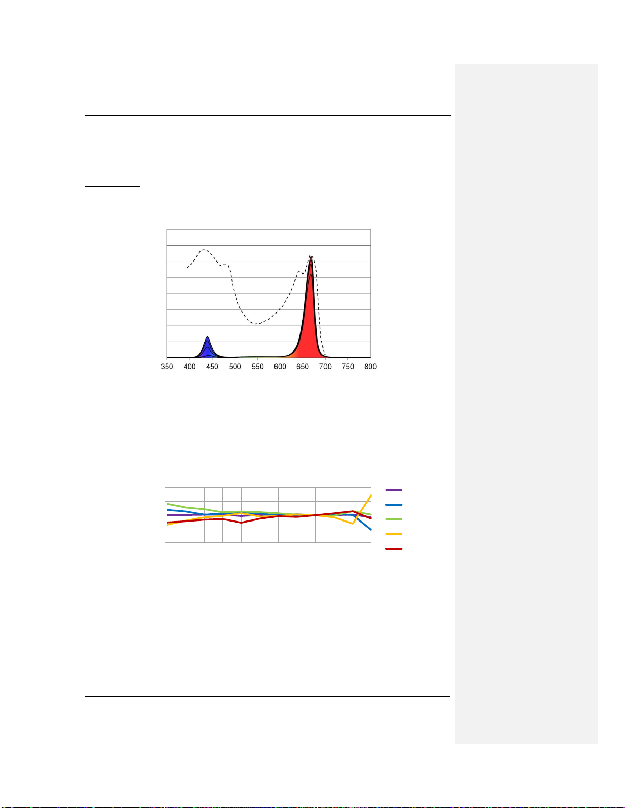
The FL300 Grow is a fixture emitting light in the photosynthetic active region of the visible
light spectrum as shown below with both the photosynthetic active region curve and the
fixtures spectral distributions.
Furthermore the spectrum can be controlled to have a spectral distribution from 2-14% blue
(400-500nm) to fit the different crops needs in their different production periods.
Below are shown the standard variations (STDV) of the contents of the light in % of PAR.
STDV is less than ±1 for all intervals when chancing the intensity.
Figure 4: STDV for the FL300 Grow spectral distribution 10% blue
For the blue interval the STDV is less than ±0.5% from fixture to fixture.
650600550500450400350300250200150100 Intensity (W)
300-400 nm
400-500 nm
500-600 nm
600-700 nm
700-800 nm
Wavelength (nm)
Figure 3: Spectral distribution of the FL300 Grow together with action spectrum
of plants. Spectral distribution for FL300 shown for 2, 6, 10, 14% blue
Light output and plant absorption on
photon level
1.0%
0.5%
0.0%
-0.5%
-1.0%

Senmatic DGT
Fionia Lighting FL300
Page 8 Rev. 30-10-2017 User manual
FL300 Sunlight
FL300 Sunlight has a spectrum designed to replica the light coming from the sun as shown
below with the curve for sunlight and the spectral distribution of FL300 Sunlight.
In the table below are the spectral distribution for sunlight and FL300 Sunlight. The STDV for
FL300 Sunlight are ±3.5 of the % of PAR.
Sunlight
FL300 Sunlight
400-500 nm
33%
33%
500-600 nm
41%
40%
600-700 nm
26%
27%
Table 1: Spectral distribution for sunlight an FL300 Sunlight
Below are shown the standard variations (STDV) of the contents of the light in % of PAR.
STDV is less than ±3.5 when chancing the intensity.
Figure 6: STDV FL300 Sunlight
-4%
-2%
0%
2%
4%
650600550500450400350300250200150100 Intensity (W)
300-500 nm
500-600 nm
600-800 nm
Wavelength (nm)
Figure 5: Spectral distribution of FL300 Sunlight for the power usages 500W,
400W, 300W, 200W and 100W together with spectral profile of sunlight.
Light output for FL300 Sunlight and
sunlight

Senmatic DGT
Fionia Lighting FL300
User manual Rev. 30-10-2017 Page 9
FL300 Grow White
The FL300 Grow White is emitting light in the photosynthetic active region of the visible light
spectrum and is a combination of the FL300 sunlight and the FL300 standard.
The luminaire is adjustable in both intensity and spectrum so it can be set to fit the individual
crops in the different productions periods the best way possible.
The spectrum can be controlled to have a spectral distribution from 2-14% blue (400-500nm)
to fit the different crops needs in their different production periods.
Wavelength (nm)
Figure 7: Spectral distribution of the FL300 Grow White together with action
spectrum of plants. Spectral distribution for FL300 shown for 2, 6, 10, 14% blue
Light output and plant absorption
on photon level

Senmatic DGT
Fionia Lighting FL300
Page 10 Rev. 30-10-2017 User manual
Controlling the FL300
The FL300 are designed so the spectrums can be controlled to fit the individual crops in
combination with LCC4 climate control systems. An alternative to the LCC4 climate control
system is Fionia Lighting Interface Software.
This chapter is a description of which parameters that can be controlled and how to control
the fixtures with LCC4 or Fionia Lighting Interface Software.
Controls
Each FL300 has an individual label showing product no., fixture type and IP address for the
fixture.
Figure 8: FL300 label
1. Product no. –This is used when ordering fixtures.
2. Fixture type –This is used in the programs to get the right program for the fixtures.
3. IP address - This is the name of the fixture, which makes it possible to communicate
with it. The IP address has eight digits.
The fixtures can be put into groups so these can be controlled together.
The light is controlled through four light channels that control a group of LEDs each. The
channels are controlled separately and the value they are set to defines how much the LEDs
are going to illuminate. To turn a channel off set the value to zero.
In the FL300 Grow the light can be controlled in the range within the values 60-255 on the
channels and in the FL300 Sunlight it can be controlled within the values 60-175.
For the FL300 Grow the colours of the LEDs controlled by the channels are as followed:
Channel A –Red one site of the fixture
Channel B –Mixed
Channel C –Blue
Channel D –Red the other site of the fixture
For the FL300 Sunlight the colours of the LEDs controlled by the channels are as followed:
Channel A –White/green one site of the fixture
Channel B –Mixed
Channel C –Blue
Channel D –White/green other site of the fixture
For the FL300 Grow White the colours of the LEDs controlled by the channels are as
followed: Channel A –Red/white one site of the luminaire
Channel B –Mixed
Channel C –White
Channel D –Red/white the other site of the luminaire
2
3
1
Senmatic DGT
Fionia Lighting FL300
User manual Rev. 30-10-2017 Page 11
Light sum control
To get the full benefits of the FL300 they should be installed together with a light sensor. The
light can be controlled with dynamic intensity, light sum for down adjustment (DLI) or both.
These two light controls are only available in the LCC4.
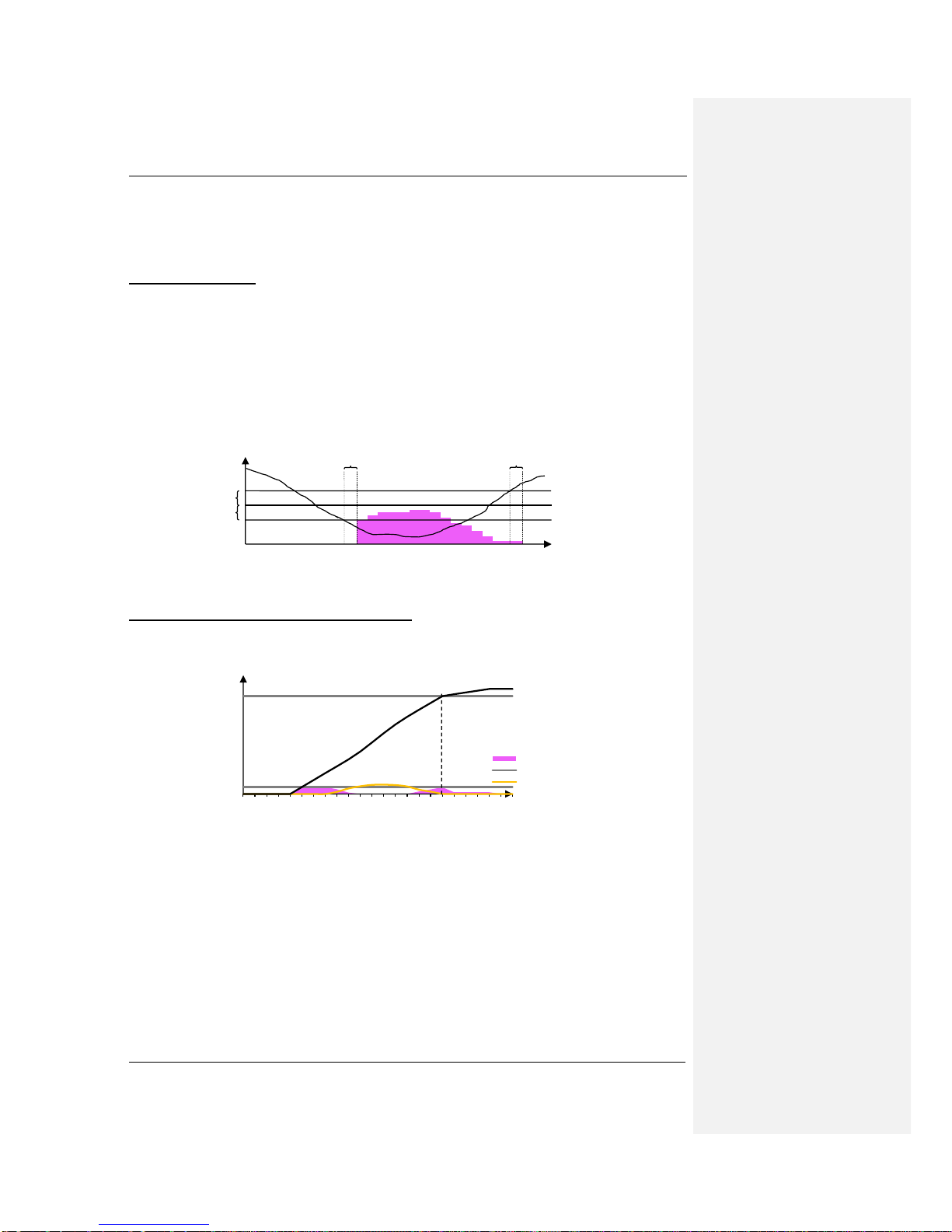
Dynamic Intensity
With dynamic intensity the FL300 will only turn on when the light level gets under the
demanded light level.
When the light is measured to be lower than the requested light level it will cause the fixtures
to turn on and when the measuring is higher than this light level the fixtures will turn off.
The hysteresis and the dynamic intensity delay prevent the fixtures to turn on and off several
times in the transitions period. The hysteresis works both over and under the light level as
shown below. (Enter the light level in LCC4 in tab Settings and hysteresis and dynamic
intensity delay in the tab Service)
The light sum for down adjustment (DLI)
The light sum for down adjustment is a demand that can be set so the plants only get the
light they can absorb on a day.
Figure 10: DLI - Light sum for down adjustment with dynamic intensity
When the demand is achieved the fixture can be turned off or turned down to a low wattage
program for long-day plants as shown above. This program will turn off at the same time as
the last program for the day is set to turn off. (Enter the demand and program for the DLI in
the LCC4 in tap Settings)
00:00 04:00 08:00 12:00 16:00 20:00
mol
Time
FL300
Light level
Daylight
Figure 9: Dynamic Intensity
µmol
Light
Light level
Hysteresis
Dyn. Intensity delay
Dyn. Intensity delay
Light level for the sun
Hysteresis
Total light sum
DLI demand
DLI achieved

Senmatic DGT
Fionia Lighting FL300
Page 12 Rev. 30-10-2017 User manual
Light intensity start –stop
Limit for the light measured outside. A measuring lower than this will cause the light to turn
on. A measuring higher than this will cause the light to turn off. In addition there is a
hysteresis, a start- and a stop delay. The hysteresis works both over and under the limit
value. See Figure 1. According the setting of the hysteresis.
Figure 1
Conditions for the light to turn on and off in the auto period.
klx
Light
Light intensity start-stop
Hysteresis
Hysteresis
Lamp off
delay
Lamp on
delay
Senmatic DGT
Fionia Lighting FL300
User manual Rev. 30-10-2017 Page 13
Programs
This chapter shows how to control the FL300 though the LCC4 climate control system with
LED control menu and through a PC with Fionia Lighting Interface Software.
Logic Climate Control 4
The LCC4 can control up to 16 houses with each up six groups of fixtures. Each house can
have two light sensors attached.
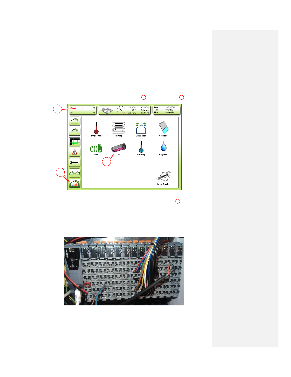
To get in to the LED settings select the Menu Overview and the LED icon .
Figure 11: Menu Overview
If the LED icon is not shown make sure you have selected the right house if you have
more houses installed. Otherwise look in the chapter Connecting the light relay
Each group of fixtures need a 24 VDC relay.
The relays for the fixtures are connected to a digital output module either X20DO8322 or
X20DO2322 In the expansion.
Figure 34: The X20 module in the expansion –with the X20DO8322 modules.
1
2
0
3
1
3
2

Senmatic DGT
Fionia Lighting FL300
Page 14 Rev. 30-10-2017 User manual
In the I/O table is shown where the relays are going to be connected. In the I/O table below
are shown an installation with four fixture groups on the position DO12-DO15.
LCC Small Exp input output table 5
Vers 01: 19-06-2012
Module
Number in
installation manual
Number on
module
Description
Digital input
X20DI2371
DI1
11
External alarm 1
DI2
21
Circ. Pump alarm
Digital output
X20DO8322
DO1
11
Valve 1 open
DO2
21
Valve 1 close
DO3
12
Valve 2 open
DO4
22
Valve 2 close
DO5
13
Vent 1 open
DO6
23
Vent 1 close
DO7
14
Vent 2 open
DO8
24
Vent 2 close
Digital output
X20DO8322
DO9
11
Screen 1 on
DO10
21
Screen 1 off
DO11
12
CO2 dose
DO12
22
Suppl. Light 1.1 / LED 1
DO13
13
Suppl. Light 1.2 / LED 2
DO14
23
Suppl. Light 1.3 / LED 3
DO15
14
Suppl. Light 2.1 / LED 4
DO16
24
Irrigation valve 1
Digital output
X20DO2322
DO17
11
Irrigation valve 2
DO18
21
M Misting Valve 1 Zone 1
Analog input
X20AI4622
AI1
12
Air temperature 1
AI2
22
RH humidity 1
AI3
15
Flow temperature 1
AI4
25
Flow temperature 2
Analog input
X20AI4622
AI5
11
CO2 sensor (4 –20 mA)
AI6
22
Air temperature 2
AI7
15
RH humidity 2
AI8
25
Local light
Analog output
X20AO2622
AO1
12
Alarm: 0V=Alarm, 10V=No Alarm High Priority
AO2
22
Alarm: 0V=Alarm, 10V=No Alarm Low Priority
Figure 35: I/O table
Setup in the LCC4 for setting the light to LED
Light menu
The light menu has five tabs.
Figure 12: Light menu's tabs
1. Overview –Gives an overview over how much light the culture have got in the
different groups and which programs are running.
2. Readings –Shows for each group –the light level, consumption and light on or off.
3. Daily settings –Enter the demand for light sum for down adjustment (DLI).
4. Settings –Select the programs for the groups.
5. Service –Select fixture type and divide the fixtures in to the groups.
Overview
1
2
3
4
5
Senmatic DGT
Fionia Lighting FL300
User manual Rev. 30-10-2017 Page 15
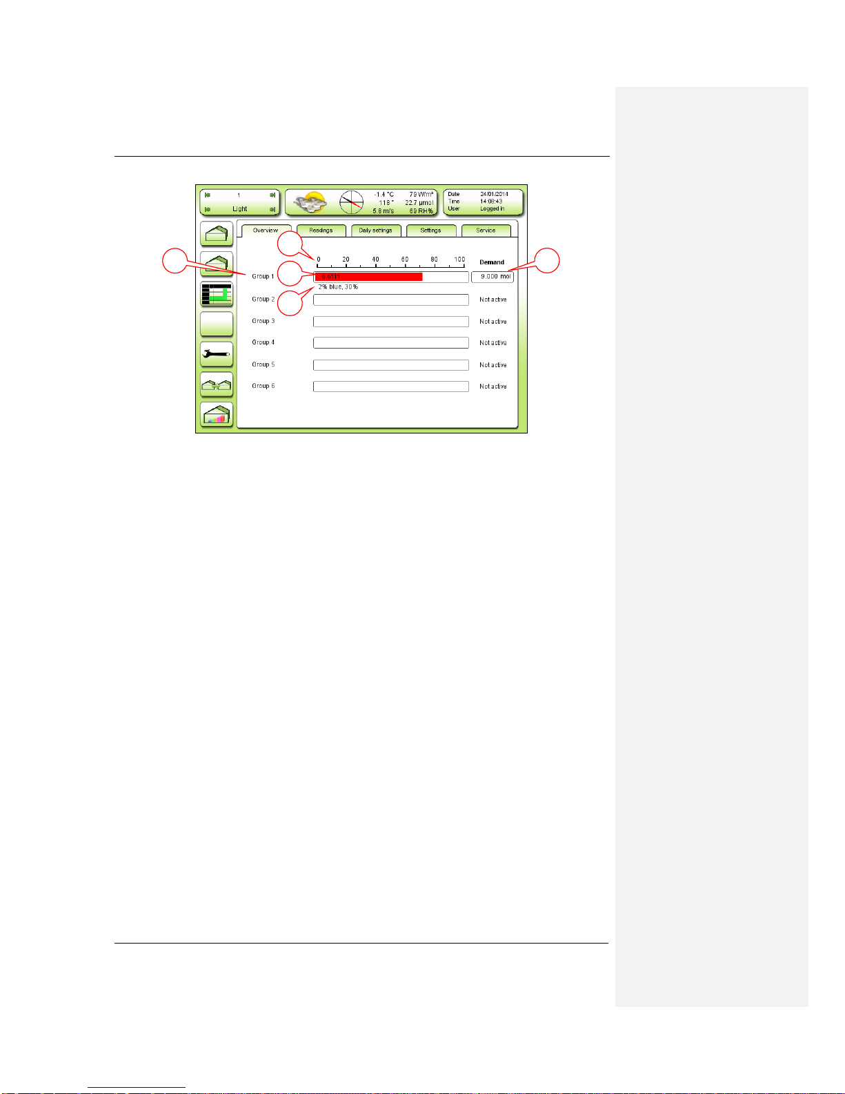
Overview is the first tap in the light menu and shows how the fixture groups are running.
Figure 13: Overview
1. The six fixture groups.
2. Total light sum for the day for the area the fixture group is illuminating.
3. The program running for the fixture group.
4. Demand on Light sum for down adjustment (DLI) for the area for the day. When
achieved the fixture group will be set to another program or turned off.
5. Scale divided in percent, to see how must of the DLI has been reached.
1
2
4
5
3
Senmatic DGT
Fionia Lighting FL300
Page 16 Rev. 30-10-2017 User manual
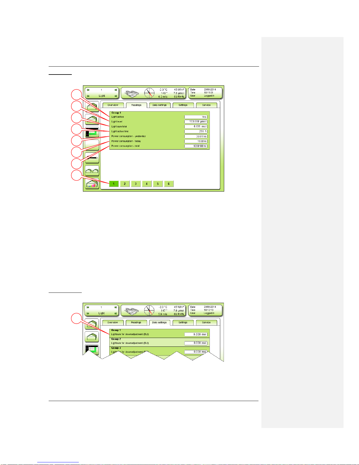
Readings
Here it is possible to see more about each group.
Figure 14: Readings
The first four points tells about the light in the group.
1. Light active –Shows if the group is on or off.
2. Light level –The light level at the moment for the area the fixture group.
3. Light sum total –The total light sum for the day for the area the fixture group is
illuminating (shown in tab Overview).
4. Light active time –The total time the fixtures have been running.
The next three points tells about the power consumption to comparison.
5. Power consumption –yesterday: The power consumed yesterday.
6. Power consumption –today: The power consumed today on till now.
7. Power consumption –total: The power consumed in the total time the fixtures have
been running.
8. To select which fixture group 1-6 to show.
Daily settings
This is a shortcut to enter the DLI for all the groups.
Figure 15: Daily settings
1. Light sum for down adjustment (DLI) –Enter the demand for the day for each group
(shown in tab Overview).
1
2
3
4
5
6
7
8
1
Senmatic DGT
Fionia Lighting FL300
User manual Rev. 30-10-2017 Page 17
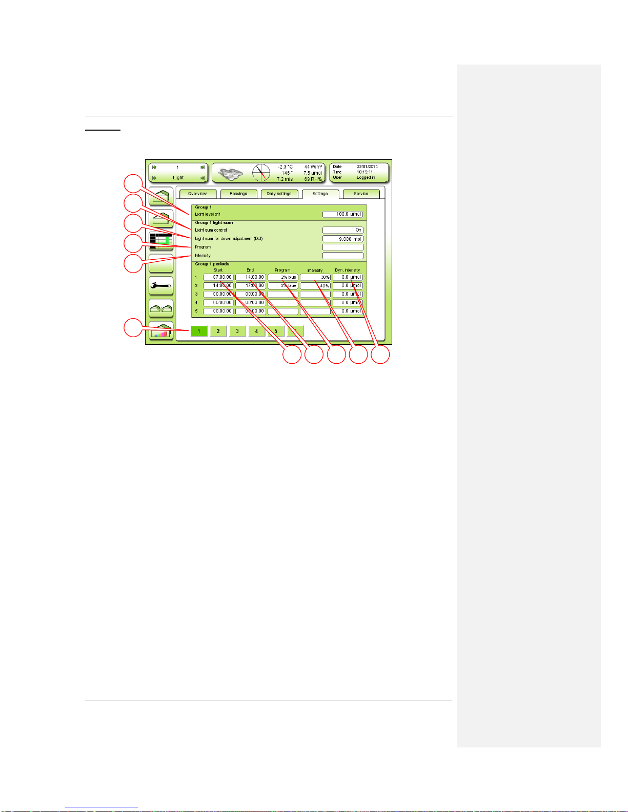
Settings
In the settings tab the groups can be set to have up five different programs throughout the
day.
Figure 16: Settings
Enter the daily programs for each group.
1. Start –Enter start time of the program (hour : minute : second).
2. End –Enter end time of the program (hour : minute : second).
3. Program –Select a program e.g. 12% blue.
4. Intensity –Select the intensity of the fixtures 20%-130% or dynamic with FL300.
5. Dyn. Intensity –Enter the demanded light level (shown in tab Readings). This will
make the intensity dynamic between the intensity steps.
6. Light level off- Enter the light level for the light measured at the weather station,
Light sum –enter the settings for the DLI.
7. Light sum control –Select “on”to use DLI.
8. DLI –Enter the demand for the day for each group (shown in tab Daily settings).
9. Program –Select a program to run when DLI has been attained ex. 12% blue.
10. Intensity –Select the intensity of the fixtures 20%-130% when DLI has been attained.
11. To select the fixture group 1-6 to enter the settings for.
1
2
3
4
5
7
8
9
10
11
6

Senmatic DGT
Fionia Lighting FL300
Page 18 Rev. 30-10-2017 User manual
Service
In the service tab it is possible select the fixture type and divide the fixtures in to the six
groups.
Figure 17: Service –Group installation
For dynamic light control and DLI there have to be a light sensor connected to the LCC4.
1. Quantum sensor –Select which light sensor should be connected to the group.
2. Dyn. Intensity hysteresis –Enter hysteresis for dynamic intensity.
3. Dyn. Intensity delay –Enter delay in the dynamic intensity.
4. Light off hysteresis - Enter Hysteresis for light off
Here the fixtures can be set into the groups
If the IP addresses, shown on the fixture labels (see Figure 8 page 10), are consecutive
they can be put into the group by entering the lowest and the highest IP address of the
fixtures.
5. Lamps in group –Shows the fixtures in the group.
6. Range start –Enter lowest fixture IP address to put in to the group.
7. Range end –Enter highest fixture IP address to put in to the group.
8. Remove –Remove the entered fixtures.
9. Add –Add the entered fixtures.
10. Select one of the six groups to edit.
11. [7] is to set up fixture type and [8] is for calibrating and test. Both are shown on the
next pages.
3
0
1
2
3
4
6
7
8
9
10
11
5

Senmatic DGT
Fionia Lighting FL300
User manual Rev. 30-10-2017 Page 19
Service settings
Here it is possible to select the fixture type and model to get the right programs to choose
from in the tab settings.
Figure 18: Service –[7] Settings
1. Lamp type –Select fixture type shown on the label (see Figure 8 page 10).
2. Power off –Select when to turn off the fixtures in the drop down menu.
a. “Off on last lamp”–Select to make all the fixtures turn off when the last
groups program is finished. The fixtures in the other groups will not turn off
before this even though there programs are finished.
b. “Off on first lamp”–Select to make all the fixtures turn off when the first
groups program is finished. The fixtures in the other groups will turn off even
though there programs are not finished.
c. “Group level”–Select to make the fixtures in a group turn off when the last
program for the group is finished. This will make the groups turn off one by
one.
3. Lamp start delay –Enter time from the fixtures turn on to the program is send to the
fixtures.
4. On/off delay –Enter length of break from fixtures turn off until they can turn on again.
5. Time for reset of light sum –Enter the time in the day for the light sum to reset.
6. Max. light intensity for light sum
If there is too much noise for the fixtures to react, the retry commands can be used.
7. Max. retry commands –Enter the number the commands must be sent.
8. Suppress receiving –Select yes if there are problems with noise.
9. Retry delay –Enter delay between commands sent.
Settings for power consumtion
10. Pulse value –Enter the value of one pulse
11. Pulse input number –Select
12. Reset total power consumption
2
0
1
2
3
4
5
6
7
8
9
10
11
12
Kommentar [LOCH1]: ??
Kommentar [LOCH2]: vælg hvilken
plus der skal tælle
noget ??
Kommentar [LOCH3]: hvad gør
denne, resetter en gang eller en gang i
døgnet ?

Senmatic DGT
Fionia Lighting FL300
Page 20 Rev. 30-10-2017 User manual
Calibration and test
Here the fixtures can be tested.
Figure 19: Service –[8] Calibration and test
The channels of the fixture can here be tested individual by selecting there value separately,
both in groups and for each fixture.
1. Channel A –Select [0], [150], [250] or enter value (0 or 060-255) for channel A.
2. Channel B –Select [0], [150], [250] or enter value (0 or 060-255) for channel B.
3. Channel C –Select [0], [150], [250] or enter value (0 or 060-255) for channel C.
4. Channel D –Select [0], [150], [250] or enter value (0 or 060-255) for channel D.
5. Fan –Select [1], [5], [A] (automatic) or enter fan speed 0-9
6. Type –Select address to control one fixture or select group to control a fixture group.
7. Lamp address –Enter fixture’s IP address or group number.
8. On/off –Turn light on and off.
To test the fixtures it is also possible to send them different commandos.
9. Send –Enter commando for the fixture.
10. Received –Answer from fixture.
11. XML –Used to install a new light program to the LCC4.
1
2
3
4
5
9
10
11
7
6
8
Table of contents


