sennebogen 830 E User manual

As of 830.0.xxxxOriginal operating instructions
830 / 07.2012
OPERATING INSTRUCTIONS
Model
830 E
Operating instructions
830.0.xxxx_us

Important notes about the operating instructions
W - 2 830 / 07.2012Original operating instructions
Foreword You have decided on a brand quality product from SENNEBOGEN.
Thank you for your selection.
It is very important to us that your SENNEBOGEN quality product
performs its work reliably, continually, and with no faults.
As you know, the reliability and durability of every machine is greatly
influenced by the regular and specialist service and maintenance work
performed on it.
We would therefore ask that you read the following service and
maintenance information thoroughly and that you implement it
accordingly.
For your own
safety Functionality, reliability, availability and advanced technology, e.g. the
use of modern materials and technology, requires specially adapted
maintenance and repair methods. Only use genuine SENNEBOGEN
spare parts. Only allow authorized SENNEBOGEN partners to perform
work on your SENNEBOGEN machine. Improperly performed
maintenance or service work may result in consequential damages and
associated safety risks.
Parts and
accessories Use only genuine spare parts and accessory products that are
authorized by SENNEBOGEN. These parts have been tested by
SENNEBOGEN for their safety and functional suitability in
SENNEBOGEN machines. SENNEBOGEN will not be held
responsible for any parts or accessory products that have not been
approved.
Warranty The warranty can become void if, for example:
Spare parts are not genuine SENNEBOGEN-approved spare parts
Maintenance is not performed at specified maintenance intervals
Maintenance has not been performed
Service and maintenance work has not been performed by a
SENNEBOGEN partner
Alterations are not authorized
In the event of damage, SENNEBOGEN reserves the right to demand
written verification that all maintenance work has been performed
correctly and completely!
SENNEBOGEN recommends special service and maintenance
contractswiththeauthorized SENNEBOGEN partnerofyourchoiceto
address these issues.

Important notes about the operating instructions
W - 3
Original operating instructions
830 / 07.2012
Notes on the
instructions Carefully read through the instructions, in particular Chapter 1
SAFETY, before beginning work with/on the machine.
CAUTION
Only work with/on the machine once you have read and completely
understood theseoperating instructions.
Refrain from operating and maintaining the machine in an unsafe
manner.
Do not operate machine if a fault has been detected.
The machine may be set up, operated and maintained by trained
personnel only.
The employer is responsible for the qualifications and training of
personnel.
These instructions are a part of the machine. Keep the instructions
in the cab at all times.
Recommended storage location: storage compartment behind the
driver's seat.
In the event of sale, disposal or loan,the operating instructions must
accompany the machine!
Contact SENNEBOGEN immediately if there is anything in the
operating instructions that you do not understand!
Your comments will help us to make the operating instructions even
more user-friendly.
Maintenance of the machine is described in separate instructions.
For reasons of clarity, the specified protective features are not
illustrated in some of the illustrations. Operation with protective
features removed is not permitted!

Important notes about the operating instructions
W - 4 830 / 07.2012Original operating instructions
Symbols and
illustrations These operating instructions contain safety instructions that highlight
dangerous working practices. These safety instructions are marked
with a warning symbol and a signal word.
Thiswarning symbol means:Attention— this concerns yoursafety and
the safety of others.
The associated signal word signifies the degree of danger:
DANGER
Is used for serious, impending danger. If this danger is not avoided,
serious physical injuries or loss of life will result.
WARNING
Is used for potentially dangerous situations. If this danger is not
avoided, serious physical injuries or death may result.
CAUTION
Is used for potentially dangerous situations. If this danger is not
avoided, physical injuries or serious material damage may result.
Notes that make the work easier or contribute to better understanding
when operating the machine are illustrated in the following way:
Note
Indicates notes that draw your attention to special features.
Note
Indicates a cross reference to other documents.
Procedures are illustrated in tabular form as follows:
Listings are marked with bullet points.
– Sub-points in listings or procedures are marked with dashes.
Optional/special equipment
Designates instructions and information that depends on special
applications or special equipment.
1Press the switch (1).
2 Actuate the control lever (2).
3Unfasten the bolt (3).

Important notes about the operating instructions
W - 5
Original operating instructions
830 / 07.2012
Glossary of terms Operator
The operator (owner of the company/company) is whoever operates
the product and uses it in accordance with its intended use or allows
the product to be operated by suitable and instructed personnel.
Operating personnel
The operating personnel are those authorized by the operator to
operate the product.
Specialist personnel
Specialist personnel are those authorized by the operator to fulfill
certain tasks such as installation, setup, repair and maintenance and
troubleshooting.
Specialists
Specialists are those who, on the basis of specialist training,
knowledge and experience with the product and in the full
knowledge of the relevant standards, can appraise the work
allocated to them and can recognize potential dangers and avoid
them.
Instructed personnel
Trained personnel are those who have received instruction in the
tasks allocated to them and in the potential dangers of misuse and
misbehavior, who have been taught about the necessary protective
features,safetymeasures,relevantregulations,accidentprevention
guidelines and operating conditions and who have proved their
abilities.
Experts
Experts are those who, on the basis of specialist training and
experience have sufficientknowledge in the area of the product and
are sufficiently aware of the relevant national occupational safety
guidelines, accident prevention guidelines, regulations and
generally recognized technical regulations (e.g. EC directives, VDE
regulations,VBG) asto beable tojudgetheoperational safety of the
machine.
Inspectors
Experts are those who are authorized by the technical authorities
(TÜV) or by a trade association to check the machinery.
Authorization by the trade association is in accordance with the
“Principles for the authorization of inspectors for the testing of
cranes” (ZH 1/518). It is linked with the issue of an identification
number. This must be stated by the inspector in the test report and/
or test memo.
Authorizations can be limited to parts of tests or specified crane
types.

Important notes about the operating instructions
W - 6 830 / 07.2012Original operating instructions
Target group The machine has been developed for demanding work.
Persons working on or with the machine must be trained or instructed
for that purpose.
Detailed information on the prior knowledge and qualifications required of
the operator can be found in Chapter 1 SAFETY of these instructions.
Which documentation
belongs with the
machine?
The following documentation belongs with the machine:
These instructions
Maintenance instructions
Spare parts catalog
Service booklet
Wiring diagrams
Hydraulic layouts
Regulatory documents
Additional documentation from pre-suppliers.
Note
The complete scope of delivery is defined in the order confirmation.

Important notes about the operating instructions
W - 7
Original operating instructions
830 / 07.2012
How is the manual
organized? The manual is divided into 10 chapters:
1: Safety
Hereyouwillfind generallyvalidsafetyinstructions andmustalways
be complied with.
2: Overview
The main components of the machine are presented in chapter 2.
3: Technical data
Here you will find basic information concerning the machine,
e.g. Working loads.
4. Start-up
Here instructions on daily start-up are provided.
5: SENNEBOGEN Control System
Here you will find information on the SENNEBOGEN Control
System.
6. Operation
Here you will find information on operating elements and work
deployment.
7. Transport
Dimensions and weights of the machine are found in chapter 7.
8: Troubleshooting
This chapter contains instructions on recognizing the causes of
faults and how to correct them.
9: Setup tasks
Chapter 9 provides information on optional work tools.
10: Appendix
Here you will find an index of and additional information, about the
magnet unit.

Important notes about the operating instructions
W - 8 830 / 07.2012Original operating instructions
How to
contact us SENNEBOGEN Maschinenfabrik GmbH
Hebbelstraße 30
94315 Straubing, Germany
Technical documentation:
Note
The addresses of the SENNEBOGEN sales and service partners can
be found on our homepage on the Internet.
Current when
going to press Ongoing development ensures advanced technology and a high level
of quality in our machines. This may result in variations between these
instructionsandyourmachine. Errorscan alsonot beexcluded. Please
understand that no legal claims can be derived from the specifications,
illustrations and descriptions within these instructions.
Copyright ©Straubing 2012, SENNEBOGEN Maschinenfabrik GmbH
Reproduction, also in part, only with written permission of
SENNEBOGEN Maschinenfabrik GmbH, Straubing, Germany.
Printed in Germany.
Telephone: +49 (0)9421 540-0
Internet: http://www.sennebogen.de
Fax for Customer Service: +49 9421 540279
Fax for spare parts depot: +49 9421 40811
Email: [email protected]
Fax: +49 9421 540380

Table of contents
0 - 1
1 Safety 1-1
1 Safety . . . . . . . . . . . . . . . . . . . . . . . . . . . . . . . . . . . . . . . . . . . . . . . . . . . 1-1
1.1 General information . . . . . . . . . . . . . . . . . . . . . . . . . . . . . . . . . . . . 1-1
1.2 Intended use . . . . . . . . . . . . . . . . . . . . . . . . . . . . . . . . . . . . . . . . . 1-2
1.3 Potential instances of misuse . . . . . . . . . . . . . . . . . . . . . . . . . . . . 1-3
1.4 Misuse . . . . . . . . . . . . . . . . . . . . . . . . . . . . . . . . . . . . . . . . . . . . . . 1-4
1.5 Other risks . . . . . . . . . . . . . . . . . . . . . . . . . . . . . . . . . . . . . . . . . . . 1-4
1.6 Machine labeling . . . . . . . . . . . . . . . . . . . . . . . . . . . . . . . . . . . . . . 1-5
1.6.1 USA identification plate . . . . . . . . . . . . . . . . . . . . . . . . . . . 1-5
1.7 Responsibilities of the employer . . . . . . . . . . . . . . . . . . . . . . . . . 1-10
1.8 Supplementary and operational equipment . . . . . . . . . . . . . . . . . 1-14
1.8.1 SENNEBOGEN CONTROL System (SENCON) . . . . . . . 1-14
1.8.2 Oils and lubricants . . . . . . . . . . . . . . . . . . . . . . . . . . . . . . 1-15
1.8.3 Diesel fuel . . . . . . . . . . . . . . . . . . . . . . . . . . . . . . . . . . . . 1-15
1.8.4 Engine oil . . . . . . . . . . . . . . . . . . . . . . . . . . . . . . . . . . . . . 1-16
1.8.5 coolant . . . . . . . . . . . . . . . . . . . . . . . . . . . . . . . . . . . . . . . 1-18
1.8.6 Fuel (not for equipment with electric motors) . . . . . . . . . . 1-20
1.9 Safety instructions . . . . . . . . . . . . . . . . . . . . . . . . . . . . . . . . . . . . 1-21
1.9.1 General . . . . . . . . . . . . . . . . . . . . . . . . . . . . . . . . . . . . . . 1-21
1.9.2 Cleaning work . . . . . . . . . . . . . . . . . . . . . . . . . . . . . . . . . 1-25
1.9.3 Safe entry and exit . . . . . . . . . . . . . . . . . . . . . . . . . . . . . . 1-27
1.9.4 Emergency exit . . . . . . . . . . . . . . . . . . . . . . . . . . . . . . . . 1-32
1.9.5 Emergency exit . . . . . . . . . . . . . . . . . . . . . . . . . . . . . . . . 1-32
1.9.6 Start-up . . . . . . . . . . . . . . . . . . . . . . . . . . . . . . . . . . . . . . 1-33
1.9.7 Operation/driving operation . . . . . . . . . . . . . . . . . . . . . . . 1-34
1.9.8 Particle filter regeneration (level 4i) . . . . . . . . . . . . . . . . . 1-35
1.9.9 Setup work . . . . . . . . . . . . . . . . . . . . . . . . . . . . . . . . . . . . 1-37
1.9.10 Decommissioning . . . . . . . . . . . . . . . . . . . . . . . . . . . . . . . 1-38
1.9.11 Maintenance . . . . . . . . . . . . . . . . . . . . . . . . . . . . . . . . . . 1-38
1.9.12 Transport . . . . . . . . . . . . . . . . . . . . . . . . . . . . . . . . . . . . . 1-41
1.10 Protective features . . . . . . . . . . . . . . . . . . . . . . . . . . . . . . . . . . . . 1-42
1.11 Disposal . . . . . . . . . . . . . . . . . . . . . . . . . . . . . . . . . . . . . . . . . . . . 1-43
1.12 Hand signals . . . . . . . . . . . . . . . . . . . . . . . . . . . . . . . . . . . . . . . . 1-44
2 Overview . . . . . . . . . . . . . . . . . . . . . . . . . . . . . . . . . . . . . . . . . . . . . . . . 2-1
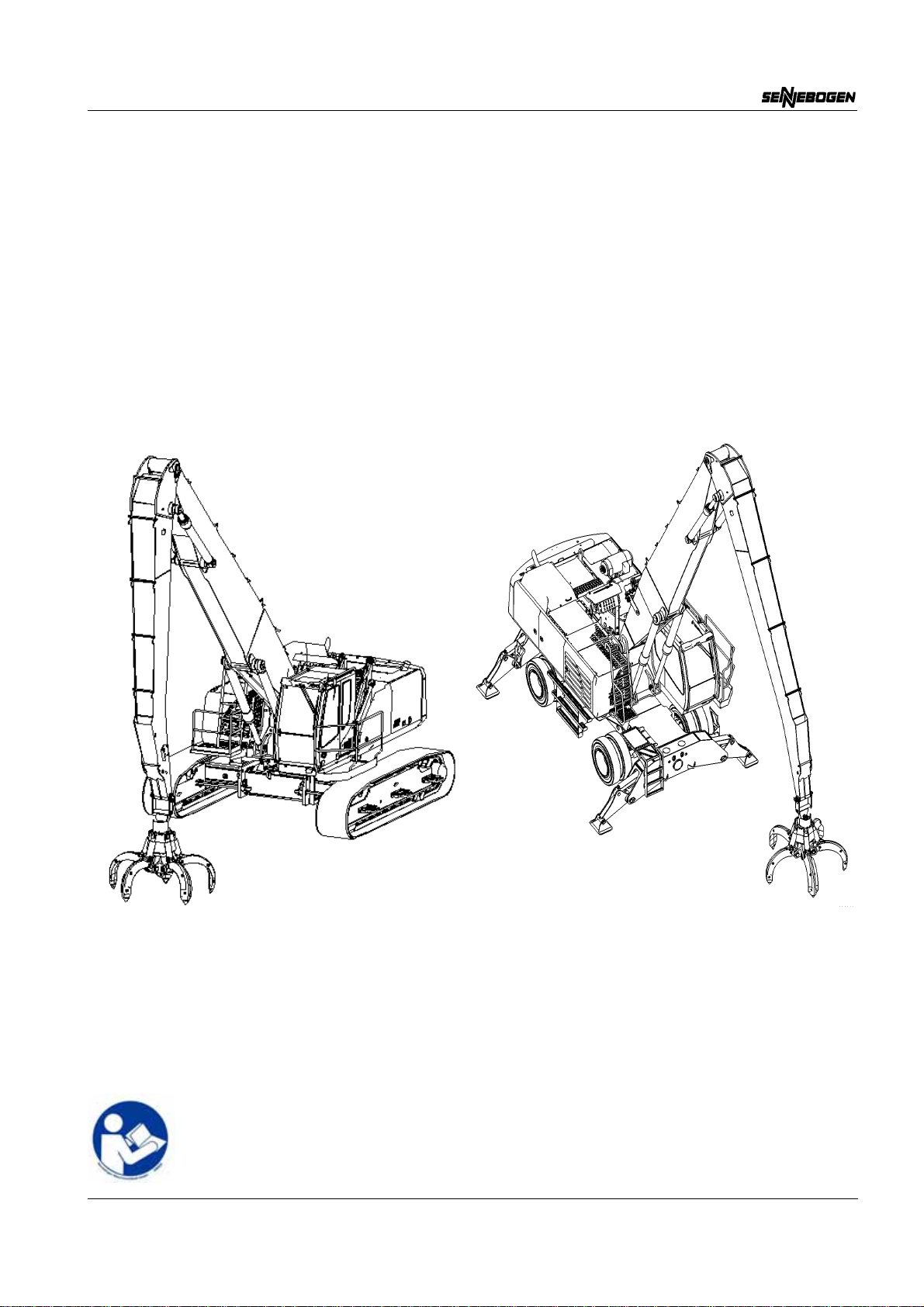
2.1 Overall machine . . . . . . . . . . . . . . . . . . . . . . . . . . . . . . . . . . . . . . . 2-1
2.2 Overall machine – crawler . . . . . . . . . . . . . . . . . . . . . . . . . . . . . . . 2-2
2.3 Undercarriage . . . . . . . . . . . . . . . . . . . . . . . . . . . . . . . . . . . . . . . . 2-3
2.3.1 4-point outrigger . . . . . . . . . . . . . . . . . . . . . . . . . . . . . . . . . 2-3

Table of contents
0 - 2
2.3.2 Outrigger front/rear . . . . . . . . . . . . . . . . . . . . . . . . . . . . . . . 2-4
2.4 Undercarriage – crawler . . . . . . . . . . . . . . . . . . . . . . . . . . . . . . . . . 2-5
2.5 Upper structure . . . . . . . . . . . . . . . . . . . . . . . . . . . . . . . . . . . . . . . 2-6
2.5.1 Side view with diesel engine . . . . . . . . . . . . . . . . . . . . . . . 2-6
2.5.2 Central electrical system . . . . . . . . . . . . . . . . . . . . . . . . . . 2-9
2.6 Equipment . . . . . . . . . . . . . . . . . . . . . . . . . . . . . . . . . . . . . . . . . . 2-11
2.6.1 Compact boom . . . . . . . . . . . . . . . . . . . . . . . . . . . . . . . . . 2-11
2.6.2 Pipe fracture safety devices . . . . . . . . . . . . . . . . . . . . . . . 2-12
2.6.3 Attachments and Vario Tool (option) . . . . . . . . . . . . . . . . 2-13
3 Technical data . . . . . . . . . . . . . . . . . . . . . . . . . . . . . . . . . . . . . . . . . . . . 3-1
3.1 General . . . . . . . . . . . . . . . . . . . . . . . . . . . . . . . . . . . . . . . . . . . . . 3-1
3.1.1 Driving engine . . . . . . . . . . . . . . . . . . . . . . . . . . . . . . . . . . 3-2
3.1.2 Level 4/IIIb . . . . . . . . . . . . . . . . . . . . . . . . . . . . . . . . . . . . . 3-2
3.2 Machine . . . . . . . . . . . . . . . . . . . . . . . . . . . . . . . . . . . . . . . . . . . . . 3-4
3.2.1 Crawler . . . . . . . . . . . . . . . . . . . . . . . . . . . . . . . . . . . . . . . . 3-5
3.3 Machine dimensions . . . . . . . . . . . . . . . . . . . . . . . . . . . . . . . . . . . 3-5
3.4 Machine weight . . . . . . . . . . . . . . . . . . . . . . . . . . . . . . . . . . . . . . . 3-5
3.5 Working loads . . . . . . . . . . . . . . . . . . . . . . . . . . . . . . . . . . . . . . . . 3-6
3.5.1 Lifting capacities 830 E . . . . . . . . . . . . . . . . . . . . . . . . . . . 3-7
3.5.2 Compact boom 8.5 m and 7.0 m . . . . . . . . . . . . . . . . . . . . 3-7
3.5.3 Compact boom 8.5 m and 7.0 m . . . . . . . . . . . . . . . . . . . . 3-8
3.5.4 Compact boom 8.5 m and 7.0 m . . . . . . . . . . . . . . . . . . . . 3-9
3.5.5 Compact boom 8.5 m and 7.0 m . . . . . . . . . . . . . . . . . . . 3-10
3.5.6 Compact boom 9.0 m and 7.5 m . . . . . . . . . . . . . . . . . . . 3-11
3.5.7 Compact boom 9.8 m and 7.5 m . . . . . . . . . . . . . . . . . . . 3-12
3.6 Warning and notice labels . . . . . . . . . . . . . . . . . . . . . . . . . . . . . . 3-13
3.7 Wind speed . . . . . . . . . . . . . . . . . . . . . . . . . . . . . . . . . . . . . . . . . 3-17
3.8 Conversion factors . . . . . . . . . . . . . . . . . . . . . . . . . . . . . . . . . . . . 3-18
3.9 Tightening torques for screws . . . . . . . . . . . . . . . . . . . . . . . . . . . 3-20
4 Start-up . . . . . . . . . . . . . . . . . . . . . . . . . . . . . . . . . . . . . . . . . . . . . . . . . 4-1
4.1 Safety instructions . . . . . . . . . . . . . . . . . . . . . . . . . . . . . . . . . . . . . 4-1
4.2 Cleaning work . . . . . . . . . . . . . . . . . . . . . . . . . . . . . . . . . . . . . . . . 4-3
4.3 Tests before start-up . . . . . . . . . . . . . . . . . . . . . . . . . . . . . . . . . . . 4-4
4.3.1 Service access door locking device . . . . . . . . . . . . . . . . . . 4-4
4.4 Initial commissioning . . . . . . . . . . . . . . . . . . . . . . . . . . . . . . . . . . . 4-5
4.5 Inspections before daily start-up . . . . . . . . . . . . . . . . . . . . . . . . . . 4-5
4.6 Tests before start-up . . . . . . . . . . . . . . . . . . . . . . . . . . . . . . . . . . . 4-9

Table of contents
0 - 3
4.6.1 Checking the demister level . . . . . . . . . . . . . . . . . . . . . . . . 4-9
4.6.2 Check fuel level . . . . . . . . . . . . . . . . . . . . . . . . . . . . . . . . 4-10
4.6.3 Lubricating the lubrication points manually . . . . . . . . . . . 4-10
4.6.4 Lubricating the lubrication points manually . . . . . . . . . . . 4-11
4.6.5 Checking the fill level in the central lubrication system . . 4-11
4.6.6 Checking the fill level in live ring toothed wheel . . . . . . . . 4-13
4.7 Checking the swing gear fill level . . . . . . . . . . . . . . . . . . . . . . . . . 4-14
4.7.1 Checking the hydraulic oil level . . . . . . . . . . . . . . . . . . . . 4-16
4.7.2 Checking and draining the fuel system . . . . . . . . . . . . . . 4-17
4.7.3 Checking the engine oil level . . . . . . . . . . . . . . . . . . . . . . 4-18
4.7.4 Checking the refrigerant level . . . . . . . . . . . . . . . . . . . . . 4-20
4.8 Lubricating the machine automatically . . . . . . . . . . . . . . . . . . . . . 4-21
4.8.1 General . . . . . . . . . . . . . . . . . . . . . . . . . . . . . . . . . . . . . . 4-21
4.8.2 Overview – central lubrication points . . . . . . . . . . . . . . . . 4-22
4.8.3 Adjusting the lubricating cycle . . . . . . . . . . . . . . . . . . . . . 4-24
4.9 Lubricating the machine manually . . . . . . . . . . . . . . . . . . . . . . . . 4-26
4.9.1 General . . . . . . . . . . . . . . . . . . . . . . . . . . . . . . . . . . . . . . 4-26
4.9.2 Central manual lubricating strip – mobile undercarriage . 4-27
4.9.3 Distributed manual lubricating points mobile undercarriage . .
4-28
4.9.4 Distributed manual lubricating points crawler undercarriage . .
4-29
4.10 Switching on machine . . . . . . . . . . . . . . . . . . . . . . . . . . . . . . . . . 4-31
4.10.1 Safety instructions . . . . . . . . . . . . . . . . . . . . . . . . . . . . . . 4-31
4.10.2 Seat belt / EU . . . . . . . . . . . . . . . . . . . . . . . . . . . . . . . . . . 4-32
4.10.3 Seat belt / USA . . . . . . . . . . . . . . . . . . . . . . . . . . . . . . . . 4-33
4.10.4 Starting the engine . . . . . . . . . . . . . . . . . . . . . . . . . . . . . . 4-34
4.10.5 Bringing the machine to operating temperature . . . . . . . . 4-36
4.10.6 Jump starting . . . . . . . . . . . . . . . . . . . . . . . . . . . . . . . . . . 4-37
4.11 Switching the machine off . . . . . . . . . . . . . . . . . . . . . . . . . . . . . . 4-38
4.11.1 Switching the engine off . . . . . . . . . . . . . . . . . . . . . . . . . . 4-38
4.11.2 Disconnecting the electrical system from the battery . . . . 4-39
4.12 Decommissioning . . . . . . . . . . . . . . . . . . . . . . . . . . . . . . . . . . . . . 4-40
4.13 Preservation and storage . . . . . . . . . . . . . . . . . . . . . . . . . . . . . . . 4-41
4.14 Starting up operating again . . . . . . . . . . . . . . . . . . . . . . . . . . . . . 4-42
4.15 Disposal . . . . . . . . . . . . . . . . . . . . . . . . . . . . . . . . . . . . . . . . . . . . 4-42
5 SENCON - Sennebogen Control System . . . . . . . . . . . . . . . . . . . . . . 5-1
5.1 Start page . . . . . . . . . . . . . . . . . . . . . . . . . . . . . . . . . . . . . . . . . . . 5-2
5.2 Overview of Functions . . . . . . . . . . . . . . . . . . . . . . . . . . . . . . . . . . 5-4

Table of contents
0 - 4
5.3 Diagnostics . . . . . . . . . . . . . . . . . . . . . . . . . . . . . . . . . . . . . . . . . . . 5-5
5.3.1 Diesel Engine . . . . . . . . . . . . . . . . . . . . . . . . . . . . . . . . . . . 5-5
5.3.2 Hydraulics . . . . . . . . . . . . . . . . . . . . . . . . . . . . . . . . . . . . . 5-6
5.3.3 Cooling . . . . . . . . . . . . . . . . . . . . . . . . . . . . . . . . . . . . . . . . 5-7
5.3.4 Average Values . . . . . . . . . . . . . . . . . . . . . . . . . . . . . . . . . 5-8
5.3.5 Service . . . . . . . . . . . . . . . . . . . . . . . . . . . . . . . . . . . . . . . . 5-9
5.3.6 Active Error/Error Memory . . . . . . . . . . . . . . . . . . . . . . . . 5-10
5.3.7 Network . . . . . . . . . . . . . . . . . . . . . . . . . . . . . . . . . . . . . . 5-14
5.3.8 Statistics . . . . . . . . . . . . . . . . . . . . . . . . . . . . . . . . . . . . . . 5-16
5.4 Settings/Parameterization . . . . . . . . . . . . . . . . . . . . . . . . . . . . . . 5-17
5.4.1 Diesel Engine . . . . . . . . . . . . . . . . . . . . . . . . . . . . . . . . . . 5-17
5.4.2 Hydraulics . . . . . . . . . . . . . . . . . . . . . . . . . . . . . . . . . . . . 5-19
5.4.3 Central lubrication . . . . . . . . . . . . . . . . . . . . . . . . . . . . . . 5-21
5.4.4 Calibration . . . . . . . . . . . . . . . . . . . . . . . . . . . . . . . . . . . . 5-23
5.4.5 Daily Operating Hours Counter . . . . . . . . . . . . . . . . . . . . 5-25
5.4.6 Display . . . . . . . . . . . . . . . . . . . . . . . . . . . . . . . . . . . . . . . 5-26
5.4.7 Activate automatic idle . . . . . . . . . . . . . . . . . . . . . . . . . . . 5-32
5.4.8 ECO mode . . . . . . . . . . . . . . . . . . . . . . . . . . . . . . . . . . . . 5-33
5.4.9 Manual fan reversal / reverse . . . . . . . . . . . . . . . . . . . . . . 5-34
5.4.10 Overload warning device (option) . . . . . . . . . . . . . . . . . . . 5-35
5.4.11 Grapple rotational speed (Option) . . . . . . . . . . . . . . . . . . 5-36
5.5 Indicator and Warning Lamps Overview . . . . . . . . . . . . . . . . . . . 5-38
6 Operation . . . . . . . . . . . . . . . . . . . . . . . . . . . . . . . . . . . . . . . . . . . . . . . . 6-1
6.1 Safety instructions . . . . . . . . . . . . . . . . . . . . . . . . . . . . . . . . . . . . . 6-1
6.2 Operator's station/cab with gallery, raising . . . . . . . . . . . . . . . . . . . 6-2
6.2.1 Driver's seat . . . . . . . . . . . . . . . . . . . . . . . . . . . . . . . . . . . . 6-5
6.3 Operating instruments . . . . . . . . . . . . . . . . . . . . . . . . . . . . . . . . . . 6-7
6.3.1 Overview with joystick steering . . . . . . . . . . . . . . . . . . . . . 6-7
6.3.2 Safety lever . . . . . . . . . . . . . . . . . . . . . . . . . . . . . . . . . . . . 6-9
6.3.3 Control lever, left . . . . . . . . . . . . . . . . . . . . . . . . . . . . . . . 6-10
6.3.4 Control lever, right . . . . . . . . . . . . . . . . . . . . . . . . . . . . . . 6-12
6.3.5 Overview for steering wheel control (optional) . . . . . . . . . 6-14
6.3.6 Overview – crawler steering . . . . . . . . . . . . . . . . . . . . . . . 6-16
6.3.7 Additional indicators . . . . . . . . . . . . . . . . . . . . . . . . . . . . . 6-17
6.3.8 Overview of the control panels . . . . . . . . . . . . . . . . . . . . . 6-18
6.3.9 Left control panel, next to driver's seat . . . . . . . . . . . . . . . 6-19
6.3.10 Right control panel, next to driver's seat . . . . . . . . . . . . . 6-20
6.3.11 Control panel, bottom right . . . . . . . . . . . . . . . . . . . . . . . . 6-21
6.3.12 Control panel, top right . . . . . . . . . . . . . . . . . . . . . . . . . . . 6-28
6.4 Additional displays (optional equipment) . . . . . . . . . . . . . . . . . . . 6-35

Table of contents
0 - 5
6.4.1 SENNEBOGEN Tool Control . . . . . . . . . . . . . . . . . . . . . . 6-35
6.4.2 Generator and magnet unit . . . . . . . . . . . . . . . . . . . . . . . 6-37
6.4.3 Camera/monitor . . . . . . . . . . . . . . . . . . . . . . . . . . . . . . . . 6-37
6.4.4 Low-temperature package (optional) . . . . . . . . . . . . . . . . 6-38
6.5 Work application . . . . . . . . . . . . . . . . . . . . . . . . . . . . . . . . . . . . . 6-44
6.5.1 Safety instructions . . . . . . . . . . . . . . . . . . . . . . . . . . . . . . 6-44
6.5.2 Moving the cab . . . . . . . . . . . . . . . . . . . . . . . . . . . . . . . . . 6-45
6.5.3 Emergency lowering — cab . . . . . . . . . . . . . . . . . . . . . . . 6-48
6.5.4 Moving the machine . . . . . . . . . . . . . . . . . . . . . . . . . . . . . 6-50
6.5.5 Stabilizing the machine . . . . . . . . . . . . . . . . . . . . . . . . . . 6-54
6.5.6 Swinging/decelerating the upper structure . . . . . . . . . . . . 6-58
6.5.7 Moving the machine (crawler undercarriage) . . . . . . . . . . 6-62
6.5.8 Changing crawler track width (mechanical) . . . . . . . . . . . 6-66
6.5.9 Changing the crawler track width (hydraulic – optional) . 6-69
6.5.10 Hoisting/lowering loads . . . . . . . . . . . . . . . . . . . . . . . . . . 6-72
6.5.11 Limit shutdown equipment . . . . . . . . . . . . . . . . . . . . . . . . 6-73
6.5.12 Bypassing the safety limit shutdown . . . . . . . . . . . . . . . . 6-77
6.5.13 Operation with the grab . . . . . . . . . . . . . . . . . . . . . . . . . . 6-78
6.5.14 Operation with the generator and magnet unit (special function)
6-79
6.5.15 Working with scrap metal shears (special function) . . . . . 6-85
6.6 Refueling the machine . . . . . . . . . . . . . . . . . . . . . . . . . . . . . . . . . 6-86
7 Transport . . . . . . . . . . . . . . . . . . . . . . . . . . . . . . . . . . . . . . . . . . . . . . . . 7-1
7.1 Safety instructions . . . . . . . . . . . . . . . . . . . . . . . . . . . . . . . . . . . . . 7-1
7.1.1 Machine dimensions . . . . . . . . . . . . . . . . . . . . . . . . . . . . . 7-2
7.1.2 Dimensions – crawler . . . . . . . . . . . . . . . . . . . . . . . . . . . . . 7-3
7.1.3 Machine weight . . . . . . . . . . . . . . . . . . . . . . . . . . . . . . . . . 7-4
7.1.4 Weight – crawler . . . . . . . . . . . . . . . . . . . . . . . . . . . . . . . . 7-5
7.1.5 Locking the upper structure . . . . . . . . . . . . . . . . . . . . . . . . 7-5
7.2 Raising the upper structure . . . . . . . . . . . . . . . . . . . . . . . . . . . . . . 7-6
7.3 Tying down the machine . . . . . . . . . . . . . . . . . . . . . . . . . . . . . . . . 7-8
8 Troubleshooting . . . . . . . . . . . . . . . . . . . . . . . . . . . . . . . . . . . . . . . . . . 8-1
8.1 Driving engine . . . . . . . . . . . . . . . . . . . . . . . . . . . . . . . . . . . . . . . . 8-1
8.2 Hydraulic system . . . . . . . . . . . . . . . . . . . . . . . . . . . . . . . . . . . . . . 8-2
8.3 Heating system . . . . . . . . . . . . . . . . . . . . . . . . . . . . . . . . . . . . . . . 8-4
8.3.1 Cooling capacity of the air conditioning . . . . . . . . . . . . . . . 8-6
8.3.2 System extremely loud . . . . . . . . . . . . . . . . . . . . . . . . . . . . 8-7
8.4 Tires and undercarriage . . . . . . . . . . . . . . . . . . . . . . . . . . . . . . . . . 8-8
8.5 Swing gear . . . . . . . . . . . . . . . . . . . . . . . . . . . . . . . . . . . . . . . . . . . 8-8

Table of contents
0 - 6
8.6 Hose lines . . . . . . . . . . . . . . . . . . . . . . . . . . . . . . . . . . . . . . . . . . . 8-8
8.7 Cab . . . . . . . . . . . . . . . . . . . . . . . . . . . . . . . . . . . . . . . . . . . . . . . . . 8-8
9 Setup work . . . . . . . . . . . . . . . . . . . . . . . . . . . . . . . . . . . . . . . . . . . . . . 9-1
9.1 Safety instructions . . . . . . . . . . . . . . . . . . . . . . . . . . . . . . . . . . . . . 9-1
9.2 Fitting the step grip on the cab . . . . . . . . . . . . . . . . . . . . . . . . . . . . 9-3
9.3 Mounting/disassembling the counterweight . . . . . . . . . . . . . . . . . . 9-4
9.3.1 Disassembling the counterweight . . . . . . . . . . . . . . . . . . . . 9-5
9.3.2 Mounting the counterweight . . . . . . . . . . . . . . . . . . . . . . . . 9-6
10 Appendix . . . . . . . . . . . . . . . . . . . . . . . . . . . . . . . . . . . . . . . . . . . . . . . 10-1
10.1 List of abbreviations . . . . . . . . . . . . . . . . . . . . . . . . . . . . . . . . . . . 10-1
10.2 Driver's seat . . . . . . . . . . . . . . . . . . . . . . . . . . . . . . . . . . . . . . . . . 10-2
10.3 Cleaning the cooling system . . . . . . . . . . . . . . . . . . . . . . . . . . . . 10-2
10.4 Installing large roller bearings, swing gears, flange connections . 10-2
10.5 Central lubrication system . . . . . . . . . . . . . . . . . . . . . . . . . . . . . . 10-2
10.6 Warranty conditions . . . . . . . . . . . . . . . . . . . . . . . . . . . . . . . . . . . 10-2
10.7 Tool Control . . . . . . . . . . . . . . . . . . . . . . . . . . . . . . . . . . . . . . . . . 10-2
10.8 Load moment indicator (LMI) . . . . . . . . . . . . . . . . . . . . . . . . . . . . 10-2
10.9 Magnet unit . . . . . . . . . . . . . . . . . . . . . . . . . . . . . . . . . . . . . . . . . 10-2
10.10Camera system/monitor . . . . . . . . . . . . . . . . . . . . . . . . . . . . . . . . 10-2
10.11Display/auxiliary heating system . . . . . . . . . . . . . . . . . . . . . . . . . 10-2
10.12Lubricants table . . . . . . . . . . . . . . . . . . . . . . . . . . . . . . . . . . . . . . 10-2

Safety - General information
1 - 1
07/2012 Original operating instructions
1 Safety
1.1 General information
The machine is built to state of the art standards. Nevertheless, there
may be dangers during its use to persons, machines and other
property, if
the machine is not utilized in accordance with its intended use
The machine is not operated or maintained by trained personnel
the safety instructions are not observed.
the machine is found to be defective.
the attachment tools attached do not comply with the relevantsafety
regulations.
The attachment tools attached are found to be defective.
National and international regulations apply in addition to the safety
instructions in these instructions.
In the Federal Republic of Germany e.g.:
Winches, Lifting and Pulling Equipment (TUR D8)
Cranes (TUR D6)
Crane inspections (BGG 905)
EU Machinery Directive 2006/42/EC
EMC Directive 2004/108/EC
Electrical Equipment in Machines (EN 60204-1)
Safety Requirements for Fluid Power Systems and their
Components — Hydraulic Systems (EN 982)
Earth-Moving Machinery — Safety (EN 474-1/-5)
Safety of Machinery (DIN EN 12100-1 and DIN EN 12100-2)
“Outdoor” guideline 2000/14/EC and 2005/88/EC
Note
If national regulations in the country of operation deviate from our
recommendations, the more stringent procedure should be followed.

Safety - Intended use
1 - 2 07/2012Original operating instructions
1.2 Intended use
Intended use of the machine consists solely of hoisting, transport and
loading of loads. Permitted attachments are:
grab
Magnet units.
In addition, in special cases:
scrap shears
Demolition hammer
Concrete crusher
Attachments An overview of all of the attachments that are currently available
including matching machine types can be found in the appendix.
WARNING
Not every attachment is suitable for every type of machine. Only the
attachments (type of construction and size) that are approved for the
respective type of machine are to be attached.
If any other attachment not listed is mounted, the user/operator is
responsible.
Observe the performance specifications of the machine. Lifting
capacities are not to be exceeded under any circumstances.
Other or additional applications are considered not in accordance with
its intended use and can endanger persons or machinery.
Work station The machine operator’s work station is in the cab of the machine.
Target group The machine has been developed for demanding work.
Persons working on or with the machine must be trained or instructed
for that purpose. Start-up, maintenance, transport, and assembly/
disassembly should only be performed by trained specialists.
Load hook:
Whenworking withthe loadhook,themachine that mustbe used,
inaccordancewithDINEN474-5,is anexcavatorused asa hoist.
For this purpose, the machine must be fitted with a load torque
monitoring device, which cuts out in the event of overload. The
lifting cylinders must be fitted with cable break safety devices.
Before commencing work in the hoisting operation, please check
the equipment on your machine and consult SENNEBOGEN
Customer Service if necessary.
Trailer:
The machine is suitable for pulling a trailer but is subject to the
permitted axle load. Questions should be directed to
SENNEBOGEN Customer Service.

Safety - Potential instances of misuse
1 - 3
07/2012 Original operating instructions
1.3 Potential instances of misuse
The following apply as potential instances of misuse, in particular:
Exceeding the permitted lifting capacities.
Using non-SENNEBOGEN parts.
Use in unauthorized ambient conditions.
Misuse by untrained and uninstructed personnel.
Inadequate fittings for the types of use (e.g. protecting the cab
against dropping objects with guard grill).
Operating on insufficiently firm subgrade.
Failure to perform the necessary inspection and maintenance work.
Neglecting to lower attached loads and boom if necessary when
shutting the machine down (e.g. work stoppages, over night).
Starting and operating the machine outside the specified starting
and operating temperature.
Insufficient pre-warming and warm-up phase.
Working in emergency operation over a longer time period.
Hoisting operation without load torque monitoring

Safety - Misuse
1 - 4 07/2012Original operating instructions
1.4 Misuse
Misuse (abuse) applies in particular to:
Hoisting, moving, and transporting of persons
Lifting loads at an angle
pulling loads
Dragging loads
Pulling free jammed loads
operation of the machine in explosive environment
exceeding the permitted safe working load
the attachment/operation of non-approved/permitted attachments
Working below or directly next to current-carrying overhead power
lines.
WARNING
Misuse excludes all liability on the part of the manufacturer! The risk is
borne solely by the user/operator.
1.5 Other risks
The safety notes in these instructions are guidelines for the safe use of
the machine by qualified machine operators. However,
SENNEBOGEN cannot anticipate every situation, which may result in
danger in practice.
Consequently, the safety notes and warnings on the machine and in
the instructions cannot be all inclusive. The owner and machine
operator still remain responsible for safety.
Warning and notice signs attached to the machine also refer to other
risks.

Safety - Machine labeling
1 - 5
07/2012 Original operating instructions
1.6 Machine labeling
The machine is provided with special warning and notice signs.
Do not remove the signs.
Ensure that all signs are undamaged and legible.
Clean labels with soap and water if necessary, not with fuel or
solvents.
Replace damaged, scratched or illegible signs with new ones.
Note
Signs are available from SENNEBOGEN (see Spare parts catalog).
1.6.1 USA identification plate
(*) Note
Thedatafor positions5,6 and7 isnotalwaysengravedon theWarning
and notice labels
1Machine type
2 Manufacturer's No. (Facility No.)

Safety - Machine labeling
1 - 6 07/2012Original operating instructions
Explanations of the stickers used on the machine:
Drilling and welding work is only to be done by authorized
SENNEBOGEN partners
Open flames prohibited!
Smoking prohibited!
Boarding prohibited!
Access for unauthorized prohibited!
Stay off!
Warning, do not clean with steam cleaner.
Warning, hazardous area.
Table of contents