Sense PSH5-M32-ASI3.2S-Ex User manual
INSTRUCTIONS MANUAL
Installation Recommendations
Intelligent Valve Monitor
PSH5-M32-ASI3.2S-Ex
2Sense
Certification information :
The Smart Valve monitor PSH5 -M32-ASI3.2S-Ex is
certified for explosive atmospheres of gases with type
of protection increased safety and encapsulation,
intrinsically safe Ex IB in output for use with solenoid
valves Exi . Has marking Ex mb and [ib ] IIB , IIA T6 Gb
IP66 being able to be installed in zones 1 and 2.
Special Conditions of Safe Use:
Valve Signalling:
The dual sensor was designed to signal rotary valves,
which rotate 1/4 turn (90 °). The sensors in the
AS-interface network are perfect for the automation of
valves, as they allow through a single cableto transmit
the open and closed state of the valve and also receive
the command to actuate the solenoid valve.
Another advantage of the network system is the
possibility of the sensor indicate a diagnosis,
especially short-circuit or open solenoid valve.
Magnetic Sensors:
The sensor consists of two magnetic sensors mounted
in the same enclosure. The sensor detects the
magnetic targets mounted on the actuator for greater
reliability, because the sensors are polarized, ie, the
sensor 1 detects only the magnet with north pole and
sensor 2 only detects the magnet with the south pole,
thus avoiding inverted detection.
System Functioning:
The electronic sensor detects the magnetic actuator
installed on the local signaller, and sends a signal to
the network with the valve positioning.
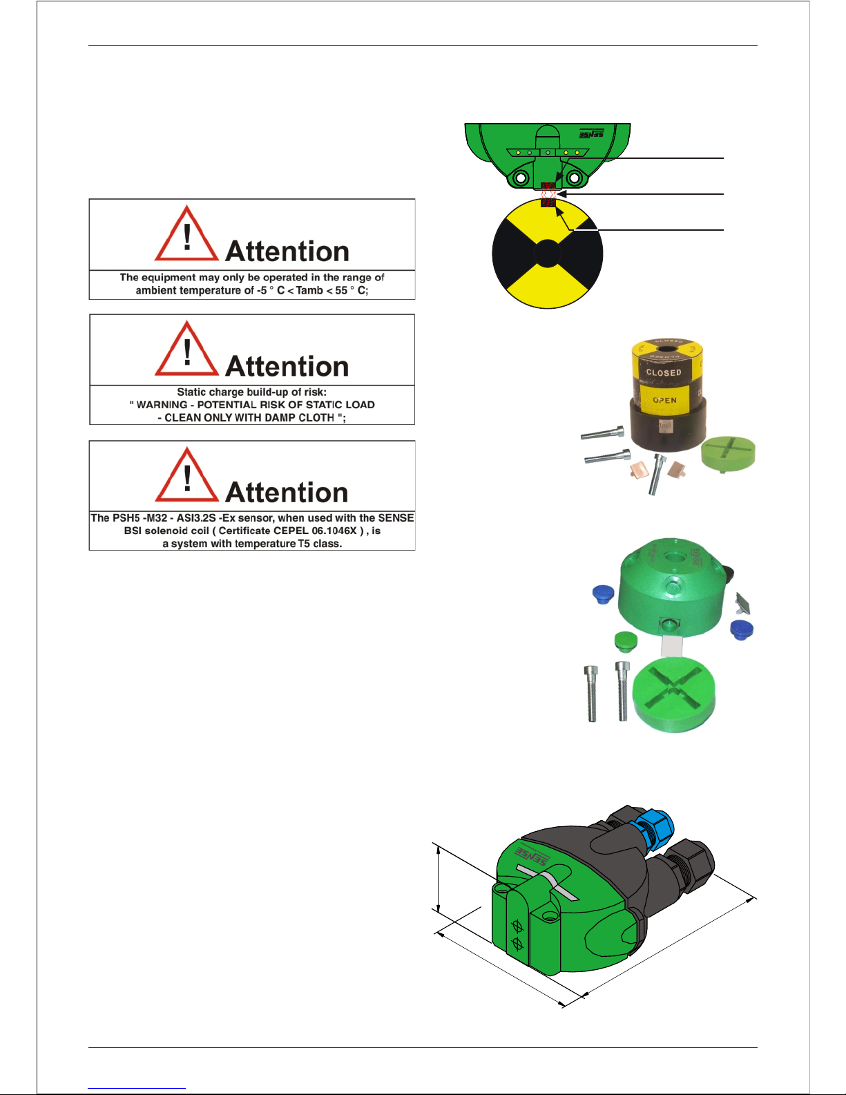
Trigger with Open/ Closed Local Signalling:
The activation kit
consists of local
indicator and its two
magnetic actuators.
The set also includes 1
distancing disc and
screws: M6x40 for fixing
the local actuator to the
shaft and the 2 screws
for fixing the M5x55
sensor.
Trigger with Local Signalling by Color:
The actuation kit
consists of the "little cup"
with its magnetic
actuators.
The set also includes 2
spacer disks, 2 green
lids , 2 blue covers and 1
black cover, and apart
from that the M6x30
screws for fixing the
actuator on the actuator
shaft and 2 M5x40
screws for fixing the
sensor are also being
supplied.
Mechanical Dimensions:
Intelligent Valve Monitor
45.0
92,5
111
Sensor Magnético
Campo Magnético
Acionador Magnético
S1 S2 FAULT ASI SOL
PSH5-M32-ASI3.2S-ExPSH5-M32-ASI3.2S-Ex
N
E
P
O
O
P
E
N

Namur Standar:
In order to standardise the coupling of pneumatic
actuators with valve position signalling elements was
established the NAMUR STANDARD, which defines
four standards for pneumatic actuator, according to
the drawing below:
Types of Shaft:
For the sensor actuator to fit perfectly, this must have
the following characteristics:
Shaft Diametre:
The sensor actuator allows shafts from 11 mm to
45mm diametre.
Shaft Fitting:
The shaft must have a Tear
4mm wide and 4mm deep so the
shoulder of the actuator fits
perfectly.
Shaft Thread:
The shaft must preferably have
a threaded hole with M6 thread,
but it is believed threads M4 or
M5, however the driver is
provided with a M6x40 screw
with the actuator site and M6x30
visual signaling to the driver
without local visual cue and
shaft must have a hole deeper
than 20mm.
Shaft Height:
M32 line sensors are supplied
with 5 mm or 10 mm spacers, thus enabling the use of
actuators on shafts of different heights. The shaft
height should be adequate so that the driver does not
scrape the bottom of the actuator and not be
suspended, moving magnetic actuators from their
position in relation to the remote signalling sensor
targets.
Sense 3
Intelligent Valve Monitor
Atuador - Vista Superior
X
Y
Atuador - Vista Lateral
Z
4mm
4mm
M5
M6
Namur 1234
DIM X 80 mm 130 mm
DIM Y
DIM Z
80 mm 130 mm
30 mm 30 mm 30 mm 30 mm
20 mm 30 mm 30 mm 50 mm
M5x8 (prof.)
11
min.
45
máx.
4
4
M6x1
12mm
CLOSED
OPEN
Eixo do Atuador
Espaçador
Acionador Espaçadores
Adicionais
5mm
10mm

Cable Installation:
Follow the procedures below to install the cables:
1 - Loosen the two screws securing the junction box to
the sensor.
2 - Detach the sensor terminal box by pulling it by
hand.
3 - Locate the three screws holding the connectors in
the junction box.
4 - With the aid of a suitable screwdriver, loosen the
three screws from the terminal box to gain access to
the connectors.
5 - Disengage the cover holding the connectors to the
terminal box.
6 - Remove the locking nut and seal rubber from the
cable gland nº 1.
7 - Prepare the cable by baring its outer cover by
maximum 40 mm.
8 - We also recommend the use of pre-insulated
terminals at the ends of the wires, to avoid problems of
poor contact or short circuit.
4Sense
Intelligent Valve Monitor
4040
55
Alicate ZA3Alicate ZA3
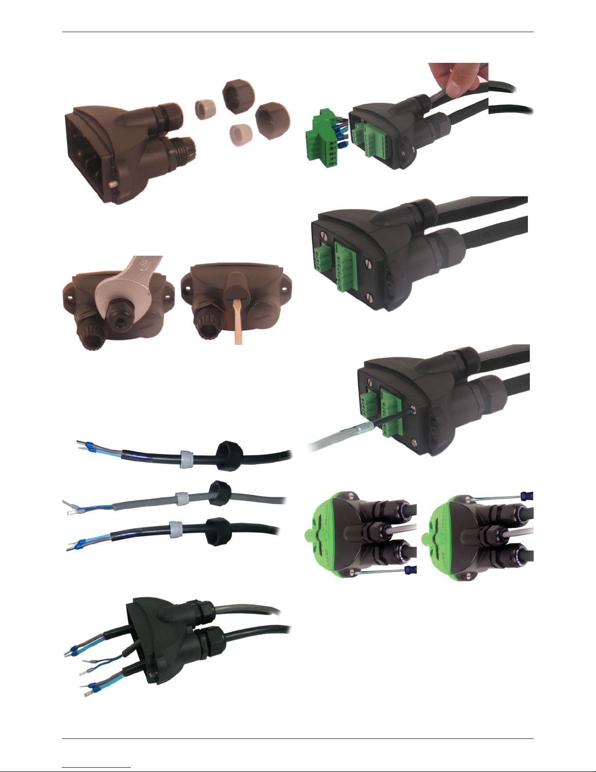
9 - The output cable network must be installed on the
cable gland 2. Repeat steps 6, 7 and 8 for this new
cable.
10 - The solenoid cable should be installed in cable
gland 3. Repeat steps 6, 7 and 8 for the cable. If the
solenoid is not used, replace the cable gland PG9 for a
buffer. Follow the steps below:
10.1 - Remove the cable gland # 3 with the help of a
19mm hex wrench.
10.2 - Put the plug provided with the kit terminal and
tighten with a screwdriver and wide slot.
11 - With all prepared cables, insert the nut of the
cable gland and the rubber seal on the cables that will
be used.
12 - Insert the cables through the cable gland holes
and mount them but do not overtighten.
13 - Fasten the wires to the terminals, observing the
connection diagram.
14 - Push the connector into the junction box, help
pulling cables.
15 - Put the connector cover, if necessary move the
cables so that the cover can be fitted.
16 - Tighten the three screws securing the connector
cover.
17 - Tighten the cable glands, plug the sensor in the
terminal box and tighten the two screws.
Sense 5
Intelligent Valve Monitor

6Sense
Intelligent Valve Monitor
Magnetic Actuators Assembly
The procedures below are for actuators with or without local visual indication.
01 - Place the magnet on the actuator on the top face marked inside.
02 - Place the magnet on the bottom of the actuator face checked out.
03 - Mount the metal cover over the magnet in your accommodation.
04 - Fold tabs for fixing the metal cover.
02
01
03
03
04
Dobra

Mounting on the Pneumatic Actuator - Actuator with Open/ Closed Local Signaling:
Montagem no Atuador - Acionador com Sinalização Visual por Cores:
Sense 7
Intelligent Valve Monitor
1- Mount the local indicator on the
actuator shaft , inserting the spacers
as needed , according to the height
axis.
2- Place the M6 screw for fixing the
local indicator to the actuator shaft
and tighten it with a proper key but do
not overtighten in order to enable the
adjustment of the triggers.
3- Mandatorily sensor 1 must be
triggered together with the solenoid
command. For this , adjust the local
indicator turning -o with a hand,
always observing the rotary direction
of the actuator.
4- The indicator allows the adjustment
of the Open / Close position indication
according to the actuator type (NO /
NC) . Adjust the local indicator
according your application and then
tighten the fixing screw.
5- Now place the monitor on the
actuator.
6- Place the acrylic on the trigger ,
then the two M5 screws and tighten
with a proper key, but do not
overtightening to avoid damaging the
acrylic.
1- Mount the local indicator on the
actuator shaft , inserting the spacers
as needed , according to the height
axis.
2- The trigger must be positioned in
order to sensor 1 activated together
with solenoid command. Observe the
rotary direction of the actuator.
3- Place the M6 screw for fixing the
local indicator to the actuator shaft
and tighten it with a proper key
4- Now place the monitor on the
actuator , then the two M5 screws and
tighten with a proper key.
5- Install the black cover on the trigger
fixing screw. Also Install the green and
blue covers for indicate de open and
close position of the valve.
6- The pictures below illustrate the
open and closed position of the valve.
Diagnoses:
8Sense
Intelligent Valve Monitor
The diagnostic tools aims to help users detect possible failures, ensuring the quality of operation of the actuator
assembly - valve, preventing problems of production, loss of lots or even accidents.
Valve (Opening and Closing) Cycle Time
Diagnosis:
This is a powerful tool that allows the sensor to
memorize the average time of opening and closing the
valve and generate a fault alarm if the preset time has
elapsed. This function is enabled by software, the bit 2
output and through dipswitches 1-4 you can configure
how many cycles the sensor learn the average time of
opening and closing of the valve.
Maintenance Diagnoses:
The sensor features powerful diagnostic tools that monitors the actuator opening and closing time and the
actuator set status - valve to know if preventive maintenance is necessary, i.e. maintenance that occurs before
the set fails, having reached a pre-user-defined level, considered sufficient to generate fatigue in components
of the set.
Valve Cycles Average Time:
It is the sum of the time that the valve completes a full
cycle (opening and closing of the valve) divided by the
number of cycles programmed to learn the sensor this
time. If the sensor is programmed to learn the average
time in cycles 4 and the sum of the times for each cycle
is equal to 60 minutes, this means that the average
time of each cycle is 15 minutes. After learning cycles,
if the average time saved is exceeded, the sensor will
indicate this anomaly.
Note: The more dense the fluid controlled by the valve,
the greater will be the number of cycles for learning
the average time.
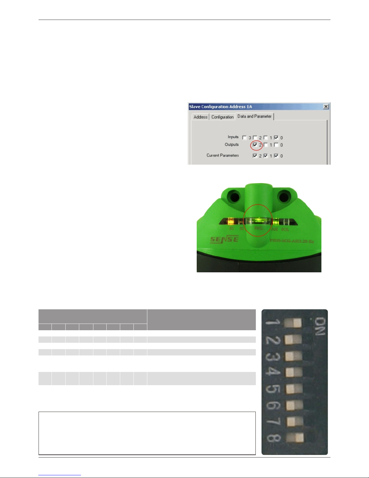
Time Tolerance: * The failure green led flashes , indicating failure in the
mean time of opening and closing the valve.
It is possible to configure through the dipswitches 5 to 8 in a tolerance time before the fault indication can be
from 10% to 40% of the average time saved by sensor.
Dipswitch Dipswitches Function
1 2 3 4 5 6 7 8
1 0 0 0 x x x x Learns with 4 actuation cycles
0100xxxxLearns with 8 actuation cycles
0010xxxxLearns with 16 actuation cycles
0001xxxxLearns with 32 actuation cycles
xxxx1000
Tolerance of 10% in time before recognising
intelligence failure
xxxx0100Tolerance of 20% in time before recognising
intelligence failure
xxxx0010Tolerance of 30% in time before recognising
intelligence failure
Notes:
- Case: 0000xxxx ou xxxx0000 => Disables intelligence function automatically.
- "1" - switches on ON. / "0" - switches on OFF.
Possible causes for failure indication are:
- Stuck valve - valve with high air leakage.
* Actuation bit of the valve opening and closing time
diagnosis.

Sense 9
Intelligent Valve Monitor
Maneuvre Counter
The sensor has a maneuvre counter that works as a maintenance diagnostic, since it allows the user to
schedule preventive maintenance for example when the valve reach the 500 full cycles (opening and closing the
valve). You can view the number of maneuvers via software, in bits 2 and 3 input or there is the possibility of
generating an alarm (via logic programming), warning that should be taken to maintain the valve.
Input Bits
Bit 0 Bit 1 Bit 2 Bit 3
Sensor 1 Sensor 2 Parametre 1 Parametre 2 No. of
Maneuvres
000 to 499
01500 to 4.999
105.000 to
49.999
11above
50.000
Output Bitsa
Bit 0 Bit 1 Bit 2 Bit 3
solenoid Maneuvre counter and
intelligent function reset Enables intelligent function not used
0 to 499 Maneuvres 500 to 4.999 Maneuvres 5.000 to 49.999Maneuvres
Above 50.000 Maneuvres Reset Function
Input and Output Bits Table:
Energy Savings and Solenoid Increased Life Span:
If the solenoid remains activated for more than 1 minute and 30 seconds, the sensor will automatically reduce its
energy-saving voltage source and increasing the life of the solenoid.
Note:Whenever valve maintenance is performed, the output bit 1 should be activated for at least 1 second to
reset the cycle count.
IMPORTANT!
On the trigger mounting and the control logic
attention should be paid because the sensor 2
should be activated together with the solenoid
command.
Signalling Leds:
Diagnoses via Signalling Leds:
10 Sense
Intelligent Valve Monitor
The smart sensor for valve signalling is equipped with five signaling leds, as follows:
Signalling Led
S1 yellow lights up when the sensor S1 is actuated
S2 yellow lights up when the sensor S2 is actuated
FAULT green/ red failure in cycle time, sensors or supply
ASI green/ red Peripheral or network communication failure
SOL yellow Indicates solenoid valve status
Led Sensor 1 Led Sensor 2 Led de Rede Led da solenóide
Led de Falha
LED Condition Description
Network Led
blinks green/ red A peripheral failure has occurred
on red no communication or address 00
on green communication with the network
Failure Led
blinks green Smart function failure (actuation cycle has bee exceeded)
blinks red Sensor actuation failure (stuck valve or with big air leakage)
on red AS-i supply < 26,5Vdc
on green no failures
Solenoid Led
off solenoid disabled
on solenoid activated
blinks yellow slowly solenoid open when activated
blinks yellow quickly solenoid in short-circuit when activated
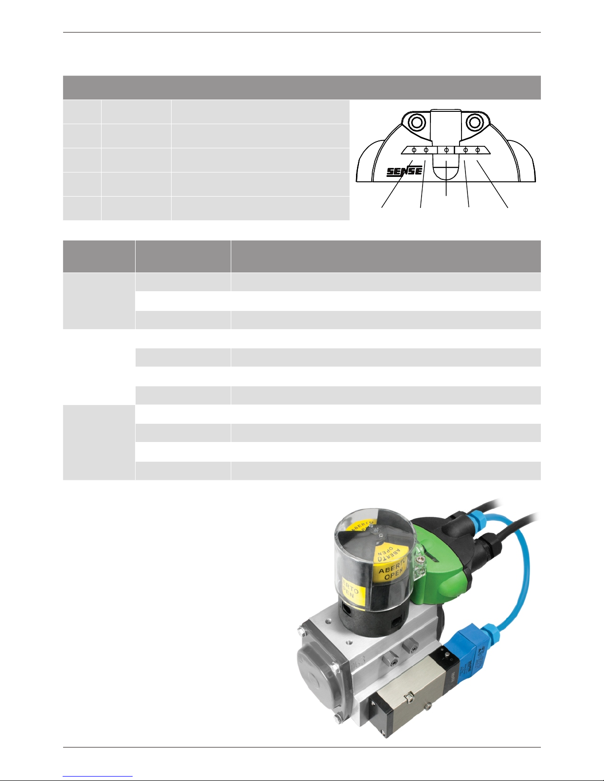
Solenoid Valve:
For the solenoid valve to be safely connected to the
valve sensor, it must be certified as Intrinsic Safety.
Sense offers sensors along with the solenoid valve,
both certificates for use in potentially explosive
atmospheres.
The valve body meets the Namur standard, which
does not require fixing accesories, as it is mounted
directly on the pneumatic actuator.
Note: Attention local indicator mounting. When the
solenoid is activated, the sensor 1 must be actuated,
otherwise it indicates a non-existent fault.

Technical Characteristics:
Connections Diagram Addressing
Sense 11
Intelligent Valve Monitor
Data PSH5-M32-ASI3.2S-Ex
Sensor Distance 5 mm
Operating Distance 5 mm
Standard Target 9 x 9 mm
Hysteresis < 3º
Repeatability < 1º
Supply voltage 30.5 Vdc via AS-Interface network
Ripple 10%
Consumption current < 40 mA
Electric Configuration AS-Interface network version 3
Maximum switching current 40 mA (Ex ib output)
Maximum switching voltage 27 Vdc
Maximum switching power 1.08 W
Maximum switching frequency 50 Hz
Output voltage drop maximum of 2 Vdc
Watch dog output de-energises upon lack of communication
Addressing 62 addresses ( 0 to 31 A or B)
Data Bits bit 0: sensor 1 ... bit 1: sensor 2
bit 2: parametre 1 ... bit 3: parametre 2
Diagnoses output shorted or open / supply out of range / failure in the
sensors or in the intelligence function
I/O and ID I/O = 7 ID = Ah ID2 = 2h
Network Signalling green / red led
Network speed 167,5 Kbps
Communication Type manchester
Network Connection screw terminal 2.5 mm² - 5 leads
Solenoid output yes
Type of solenoid low power
Solenoid Connection screw terminal 2.5mm² - 2 vias
Solenoid Signalling Yellow led
Housing PBT
Protection rate IP 66
Weight < 250 g
Operating Temperature - 25ºC to + 55ºC
ASI -ASI -
ASI +ASI +
SOL-SOL-
11
22
SOL +SOL +
++
--
The addressing on the AS-Interface network is configured
via software or manual programmer.
Selection
IO:7 - ID:A - ID2:2
U=30,5Vdc - IL=40mA
SOL+
SOL
-
ASI -
ASI+
Not Used
Not Used
Not Used
For our example we will configure the sensor to learn
that the average time for valve actuation in 16 cycles
and 10% tolerance in time before indicating failure in
the function of intelligence. For our example the
software used for configuration is the ASI-Control
Tools.
1 - Attach the sensor according to the connection
diagram and connect a PC with the ASI-Control Tools
software installed.
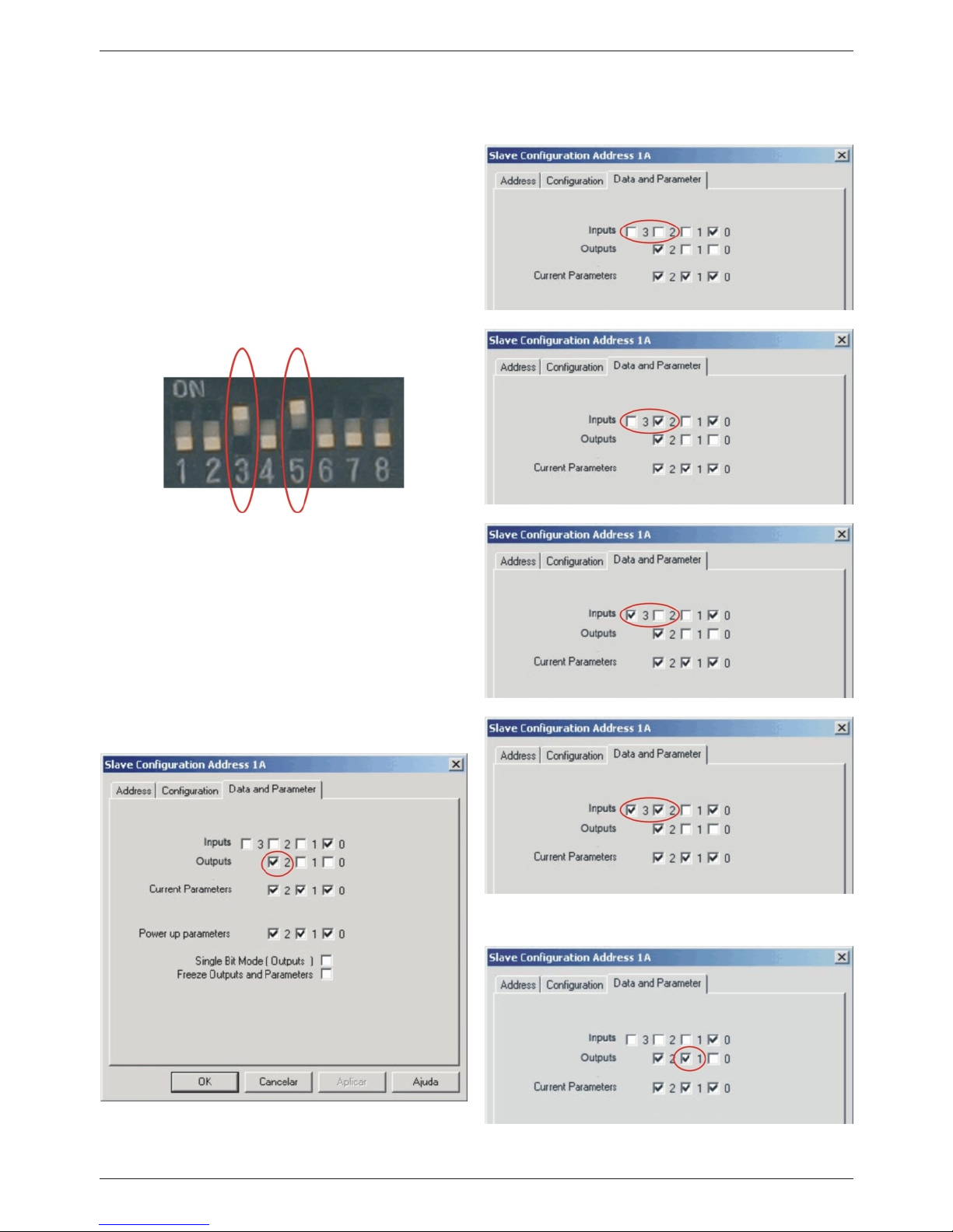
2 - Place the dip number 3 to "ON", the sensor will
learn it the average time of operation of the valve 16
cycles.
3 - Place the dip number 5 to "ON" so that the
tolerance in time before indicating failure is 10%.
NOTE!The other dips should all remain in the "OFF"
position.
4º - Make the setting for the sensor to be recognized
by the software.
5 - To enable the intelligence function, you must set bit
2 output for this, open the slave configuration screen
by double-clicking on it.
6 - When you open the screen click on "Data and
Parameter" tab and click on bit 2 output to enable it.
7º - The amount of maneuvering of the valve is read in
input bits 2 and 3, as the figures below:
0 to 499 Maneuvres:
500 to 4.999 Maneuvres:
5.000 to 49.000 Maneuvres:
Above 50.000 Maneuvres:
NOTE!When doing maintenance of the valve to reset
the maneuvre counter, for this, enable output bit 1 for
at least one second.
12 Sense
Intelligent Valve Monitor
Sensor Functions Configuration Example:
Rua Tuiuti, 1237 - Tatuapé - 03081-000 - São Paulo - SP - Fone: (11) 2145-0444 - Fax: (11) 2145-0404 - e-mail: vendas@sense.com.br - www.sense.com.br
We reserve the right to modify the information contained herein without notice EA3000849C - 09/2015
Table of contents


