Temperature
Controller
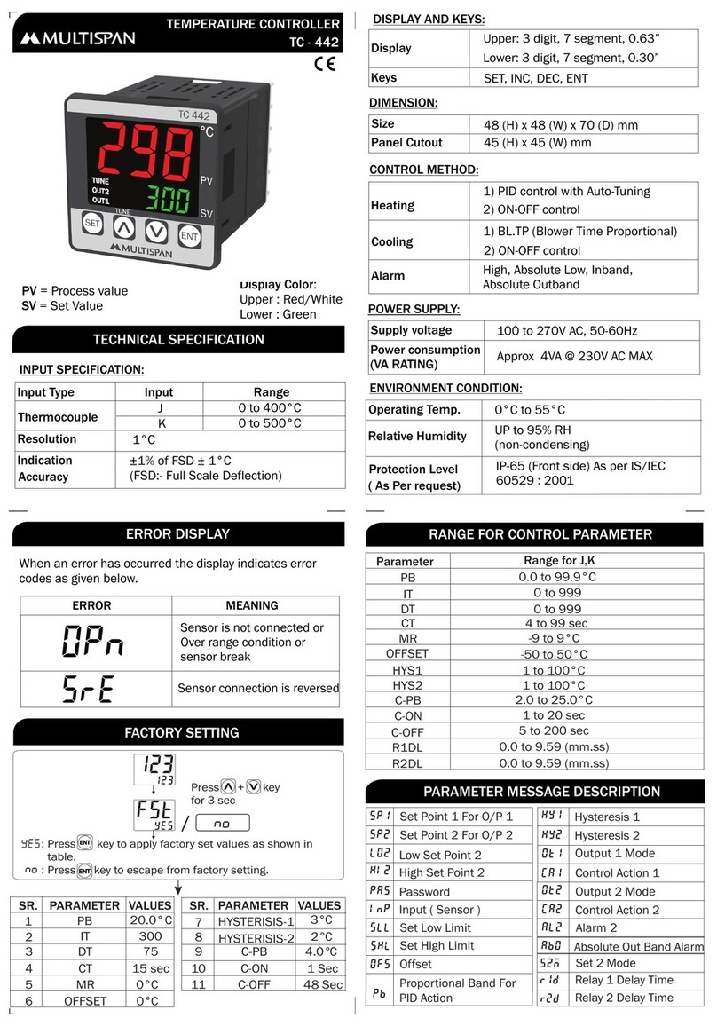
TECHNICAL SPECIFICATION
MECHANICAL DIMENSIONS
INSTALLATION INSTRUMENT CONFIGURATION
Wiring Guidelines:
SAFETY PRECAUTIONS :
CAUTION :
92
68
92
68
-2
-2
Tolerance: 92
Tolerance: 68
x
x
+0
+0
-2
-2
92
68
+0
+0
Panel Cutout
Panel Cutout
96
72
96
72
Front View
Front View
For installing the meter
1. Prepare the panel cutout with proper dimensions
as shown above.
2. Push the meter into the panel cutout.
Secure the meter in it’s place by fitting the clamp
on the rear side. Fit the clamps on both the sides
in diagonally opposite location for optimum fitting.
3. For proper sealing, tighten the screws evenly with
required torque.
Terminal screw tightening torque:
0.68 Nm to 0.79 Nm (6.018ln-Lb to 6.992 ln-Lb)
Screw clamp tightening torque: 0.1N-m
(0.885 Lb-inch)
1) To prevent the risk of electric shock power supply to
the equipment must be kept OFF while doing the
wiring arrangement.
2) Wiring shall be done strictly accordingly to the
terminal layout with the shortest connection.
Confirm that all connection are correct.
40
50
Side View
Side View
Do not use the equipment if there is any
mechanical damage
Ensure that the equipment is supplied with
correct voltage
All safety related conditions, symbols and
instruction that appear in this operating manual
or on the equipment must be strictly followed to
ensure the safety of the operating personnel as
well as the instrument.
If the equipment is not used in a manner
specified by the manufacturer it might impair the
protection provided by the equipment.
If there is physical damage to the unit then do not
use it.
Read complete instruction prior to installation
and operation of the unit.
Features
Factory Set Input
Economical Model
User Friendly & Easy to Program
4 Digit 0.8inch Bright LED Display with
RED and WHITE color option in TC-911
*Note: If the instruments stays in idle condition
while inside the Configuration Menu for more
than 30 seconds, then it will automatically exit
the configuration menu.
*Installation Note:
It is been advised that the settings should be
done by a professional, after going through
user operating manual and after having
understood the application.
Input Types
Resolution
Indication
Accuracy
Input Range
J : 0 to 850°C, K : 0 to 1200°C
PT-100: -50.0 to 400.0°C
J / K
PT-100
2W/3W
1°C
±1% of FSD ± 1°C
Display
Control Mode
Size (mm)
TC-711
TC-911
Size (mm)
Keys
Panel Cutout
Panel Cutout
Relay
Supply Voltage
Relay Type
Power Consumption
(VA Rating
Rating
4 Digit, 7 Segment LED,
0.8 inch in TC-911, 0.56 inch in TC-711
ON-OFF Control
96 (H) x 96 (W) x 40 (D) mm
72 (H) x 72 (W) x 50 (D) mm
1 Nos
230V AC, 50-60Hz
1C/O (NO-C-NC)
10A (Resistive Load)
SET, UP, DOWN
92 (H) x 92 (W) mm
68 (H) x 68 (W) mm
(FSD:- Full Scale Deflection)
OUTPUT SPECIFICATION:
POWER SUPPLY:
INPUT SPECIFICATION:
DISPLAY AND KEYS:
DIMENSION:
CONTROL ACTION
SET POINT MENU
ERROR CONDITIONS
ENVIRONMENT CONDITION:
KEY OPERATION
Relative Humidity
Protection Level
(As per request)
Operating Temp.
Key
0°C to 55°C
Funtion
UP to 95% RH
(non-condensing)
IP-65 (Front side)
As per IS/IEC 60529 : 2001
4VA @ 230V AC MAX
225
S E T
S
S
e
e
c
E
Set Value
Set Point Menu
It means Input Sensor Not Connected
or any error with connected sensor.
In such case please check the sensor connections
This means Input Sensor Reverse;
In such case please check the sensor connections
If the display shows below message
If the display shows below message
Using up & down key
to change SET point
Press the SET key
it will store the latest
SET Value
press SET key
Long press key
Dimensions for TC-911
Dimensions for TC-711
TC-911, TC-711
To enter parameter Setting menu
UP Key
Down Key
PRESS KEYFUNCTION
OPERATOR MODE
Press Key
SET Key
(Long Press to Enter Set Point Menu)
UP Key
(To increase the value/navigate in menu)
Down Key
(To decrease the value/navigate in menu)
SET+UP KEY
(Long press to enter parameter menu)
+ ** Important Note:
Range for J Type Input : 0 to 850°C
Range for K Type Input : 0 to 1200°C
Range for PT 100 Input : -50.0 to 400.0°C

