SenseTek CEA10 User manual

Technical Manual
Installation and Service
BlazeCut Automatic Fire Suppression System
Indirect Clean Agent Systems
CEA10
CEA35
CFA10
CFA35
CNO10
CNO35

www.blazecut.com Page 2 of 93
technical@blazecut.com ILP CLEAN AGENT MANUAL-ILPCAM1904
BlazeCut and the BlazeCut logo are the registered trademarks of BlazeCut © 2019 BlazeCut, All rights reserved
TABLE OF CONTENT:
1. INTRODUCTION.................................................................................................................. 4
2. BASIC INFORMATION ABOUT THE SYSTEM.......................................................................... 5
2.1. TECHNICAL SPECIFICATION AND TYPES................................................................................... 8
2.2. USE OF THE SYSTEM................................................................................................................. 8
3. COMPONENTS OF THE SYSTEM AND THEIR DESCRIPTION .................................................... 9
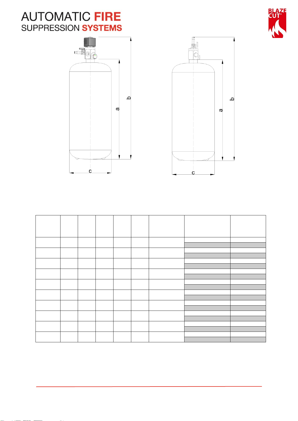
3.1. CYLINDER.................................................................................................................................. 9
3.2. VALVE OF THE CYLINDER........................................................................................................ 12
3.3. BLAZETUBE DETECTION ......................................................................................................... 18
3.4. PRESSURE GAUGE .................................................................................................................. 20
3.5. BLAZETUBE FITTINGS ............................................................................................................. 21
3.6. BLAZETUBE END OF LINE DEVICES......................................................................................... 21
3.7. BLAZEWIRE............................................................................................................................. 22
3.8. FASTENING MATERIAL ........................................................................................................... 26
3.9. LABELS.................................................................................................................................... 27
3.10. INSTALLATION OF DISTRIBUTION NETWORK......................................................................... 29
4. DEFINITION OF LEGAL REQUIREMENTS ............................................................................. 37
5. INFORMATION ON EXTINGUISHING AGENT USED.............................................................. 37
5.1. DESCRIPTION OF HFC GASES.................................................................................................. 38
5.2. DESCRIPTION OF NOVEC 1230 (FK-5-1-12)............................................................................ 38
5.3. PERMISSIBLE USES OF EXTINGUISHING AGENT..................................................................... 39
5.4. VOLUME COVERAGE .............................................................................................................. 39
5.5. SOME PHYSICAL AND CHEMICAL PROPERTIES ...................................................................... 43
5.6. IMPROPER USES OF EXTINGUISHING AGENT ........................................................................ 44
5.7. WARNINGS............................................................................................................................. 44
5.8. HANDLING HFC GASES........................................................................................................... 45
6. INSTRUCTIONS FOR INSTALLATION OF THE SYSTEM .......................................................... 46
6.1. GENERAL RULES ..................................................................................................................... 46
6.2. INSTALLATION AND PLACEMENT OF THE CYLINDER ............................................................. 47
6.3. MULTIPLE CYLINDERS CONNECTION...................................................................................... 50
6.4. INSTALLATION OF THE BLAZETUBE DETECTION .................................................................... 52
6.5. PRESSURIZATION OF THE BLAZETUBE DETECTION SYSTEM.................................................. 58
6.6. FINAL INSPECTION OF THE SYSTEM INSTALLATION............................................................... 61
7. REGULAR INSPECTION AND MAINTENANCE OF THE FIRE SUPPRESSION SYSTEM ................ 61
7.1. COMPREHENSIVE INSPECTION OF THE SYSTEM.................................................................... 62
7.2. INSPECTION OF PRESSURE IN THE SYSTEM ........................................................................... 62
7.3. PRESSURIZATION OF THE SYSTEM......................................................................................... 63
7.4. INSPECTION OF WEIGHT OF EXTINGUISHING AGENT IN SYSTEM ......................................... 67
7.5. REMOVAL OF THE SYSTEM FROM THE SERVICE .................................................................... 67
8. OPERATION OF SYSTEM BLAZECUT IN CASE OF FIRE .......................................................... 68
10. DISAMBLEMENT OF THE SYSTEM ...................................................................................... 71
11. MAINTENANCE OF THE SYSTEM, REPLACEMENT OF COMPONENTS.................................... 72
11.1. GENERAL RULES ..................................................................................................................... 72
11.2. REPLACEMENT OF THE CYLINDER.......................................................................................... 72

www.blazecut.com Page 3 of 93
technical@blazecut.com ILP CLEAN AGENT MANUAL-ILPCAM1904
BlazeCut and the BlazeCut logo are the registered trademarks of BlazeCut © 2019 BlazeCut, All rights reserved
11.3. REPLACEMENT OF THE BLAZETUBE DETECTION.................................................................... 73
11.4. RELEASE OF THE PISTON OF THE VALVE IN CASE OF ACCIDENTAL OPENING........................ 73
11.5. CLEANING THE SYSTEM.......................................................................................................... 74
11.6. DECLARATION OF CONFORMITY............................................................................................ 74
12. LIST OF ANNEXES.............................................................................................................. 74
ANNEX NO. 1.............................................................................................................................. 75
1.1. PRESSURE SWITCH APS001.................................................................................................... 75
1.2. INSTALLATION OF THE PRESSURE SWITCH............................................................................ 75
1.3. PRESSURE TRANSDUCER ATA100 .......................................................................................... 76
1.4. ELECTRICAL CABLES AND CONDUITS ..................................................................................... 77
ANNEX NO. 2.............................................................................................................................. 78
2. BASIC INFORMATION ABOUT THE COMPONENTS.............................................................. 78
2.1. INSTALLATION OF THE SOLENOID VALVE .............................................................................. 78
2.2. PRESSURIZATION OF THE DETECTION SYSTEM...................................................................... 79
2.3. FUNCTION OF THE SOLENOID VALVE..................................................................................... 81
2.4. PRESSURIZATION OF THE SYSTEM......................................................................................... 81
ANNEX NO. 3.............................................................................................................................. 82
3. BASIC INFORMATION ABOUT THE COMPONENTS.............................................................. 82
3.1. INSTALLATION OF THE REMOTE ACTUATOR ......................................................................... 82
3.2. PRESSURIZATION OF THE LOP LINE........................................................................................ 83
3.3. REPLACEMENT OF THE MEMBRANE OF THE REMOTE ACTUATOR ....................................... 86
3.4. FUNCTION OF THE REMOTE ACTUATOR................................................................................ 87
3.5. PRESSURIZATION OF THE SYSTEM......................................................................................... 87
ANNEX NO. 4.............................................................................................................................. 88
4. BASIC INFORMATION ABOUT THE COMPONENTS.............................................................. 88
4.1. INSTALLATION OF THE REMOTE ACTUATOR ......................................................................... 88
4.2. PRESSURIZATION OF THE LOP LINE........................................................................................ 89
4.3. REPLACEMENT OF THE MEMBRANE OF THE REMOTE ACTUATOR ....................................... 91
4.4. PRESSURIZATION OF THE SYSTEM......................................................................................... 92
ADDITIONAL NOTES.................................................................................................................... 93

www.blazecut.com Page 4 of 93
technical@blazecut.com ILP CLEAN AGENT MANUAL-ILPCAM1904
BlazeCut and the BlazeCut logo are the registered trademarks of BlazeCut © 2019 BlazeCut, All rights reserved
1. INTRODUCTION
MANUFACTURER INFORMATION
BlazeCut s.r.o., Brusnicová 3299/7, Chorvátsky Grob 900 25, Slovak Republic
GLOBAL HEAD OFFICE
BlazeCut Pty Ltd, 45 Evans St, Balmain NSW 2041 Australia
+61 2 8006 1300
www.blazecut.com; techn[email protected]
INSTRUCTIONS FOR USE OF THE MANUAL
This manual is intended to supply technical information for the trained and authorized BlazeCut Group.
Any personnel performing installation, inspection, maintenance or replacement of components with
the BlazeCut system shall have this manual available and proceed solely in accordance with it.
Failure to follow the instructions in this manual and any other BlazeCut manuals may result in system
malfunctioning, causing damage to the protected equipment and presents serious danger to the life
and health of others.
SAFETY FIRST
Please read this manual in its entirety. Operation and installation instructions need to be fully
understood before this BlazeCut product is installed. Failure to do so may void warranty. Your local
governing regulations for safety and compliance must be followed.
In the figures the descriptions of the components are marked with numbers, the descriptions of steps
are marked with a letter “S“and a number.
WARNINGS AND CAUTIONS
This symbol in the text represents warning of specific risk, danger, or warning of described procedure.
Failure to follow the instructions in the text marked with this symbol may result in damage to
property, loss of warranty, unforeseeable event or threat to safety, health or life of persons
performing the operation on the system or persons in their vicinity. Do not proceed contrary to the
instructions marked with such symbol.
FURTHER INFORMATION
BlazeCut® is a registered trademark of BlazeCut and is recorded in the Register of Community Trade Marks.
If any of the instructions in this manual are unclear or in case of further questions contact the BlazeCut Team.
This document is the property of BlazeCut It is prohibited to reproduce it, copy it in whole or in part, or provide third parties
with any related information without prior written consent of BlazeCut.
WARNING
Please ensure that the safety instructions are fully understood before the
equipment is put into service.
Do not modify any part of the BlazeCut components as this may cause
serious injury or a failure of the system.
Always wear the appropriate protective equipment and clothing whilst
installing or servicing.

www.blazecut.com Page 5 of 93
technical@blazecut.com ILP CLEAN AGENT MANUAL-ILPCAM1904
BlazeCut and the BlazeCut logo are the registered trademarks of BlazeCut © 2019 BlazeCut, All rights reserved
2. BASIC INFORMATION ABOUT THE SYSTEM
EXPLANATION OF TYPE NAME CAPTION
1. Part of caption stating the BlazeCut system series
C (cylinder) –type of system using cylinder
2. Part of caption stating extinguishing agent used
EA –extinguishing agent used HFC-227ea
FA –extinguishing agent used HFC-236fa
NO –extinguishing agent used Novec 1230 (FK-5-1-12)
3. Part of caption stating valve used
10 –Code name of the valve with the solenoid, optionally with one BlazeTube detection outlet (Ø 6
mm) or additional M10x1 adaptor
35 –Code name of the valve without the solenoid, one BlazeTube detection outlet, Ø 6 mm
4. Part of caption stating quantity of extinguishing agent
e.g. “2“means system with the 2 kg of extinguishing agent
5. Part of caption stating quantity of nozzles.
6. Part of caption stating Kit for vehicle or mobile application.
ASSOCIATED NAMES
In certain cases it is needed to state use of multiple systems. In these cases associated name is used.
Example:
CEA(FA)10 –includes all systems BlazeCut with the cylinder (C) with the extinguishing agent used HFC-227ea (EA)
and HFC-236fa (FA) with the valve type “10“with integrated solenoid.
DESCRIPTION OF SYSTEM
Commercial name: BlazeCut
Characteristics: automatic fire suppression system
Type: Indirect Low Pressure (ILP)
Functionality: BlazeCut system is designed to protect closed spaces, from fire using volume fire suppression, e.g.:
-Engine compartments of mobile equipment and vehicles
-Electrical switchboards, fuse boxes, electrical supply sources, battery spaces,
-Network installations, voltage junctions,
-Server racks,
-Fume cabinets,
-Telecom tower shelters,
-Elevator engine rooms,
-CNC machines,
-AC devices, ventilation devices,

www.blazecut.com Page 6 of 93
technical@blazecut.com ILP CLEAN AGENT MANUAL-ILPCAM1904
BlazeCut and the BlazeCut logo are the registered trademarks of BlazeCut © 2019 BlazeCut, All rights reserved
-Spray boxes for paint application,
-Mini power plants,
-Archives,
-Gas boilers, gas regulation stations,
-Windturbines,
-Other.
The fire suppression system operates by detecting fire using a pneumatic BlazeTube detection connected to the
cylinder valve. The BlazeTube detection is placed in the protected enclosure and is under constant pressure
whereby keeping the valve piston closed. In case of fire the BlazeTube detection degrades by the effect of fire or
high temperature. When the BlazeTube detection is disrupted, the pressure in it decreases (LOP system - Loss of
Pressure system) and the valve piston of the cylinder is open. The fire suppression system activates and the entire
extinguishing agent is released. The detection system is independent of any electrical supply and operates solely
on physical principles.
Alternatively the system can detect the fire using electronic devices like Linear Heat Detector (LHD) BlazeWire,
smoke/heat detectors or other. These electronic devices must be used in connection with the integrated solenoid
valve (valve type 10) or end of line solenoid valve in connection with the BlazeTube detection (valve type 35).
BlazeCut systems CEA(FA,NO)10 have integrated solenoid valve (valve type 10), which allows activation of the
system by receiving signal from external device (alarm panel, fire panel, detector etc.).
BlazeCut systems BlazeCut CEA(FA,NO)35 have the valve without integrated solenoid (valve type 35) but the
solenoid can be connected to end of BlazeTube detection as end of line device CSV001.
The system is referred to as indirect, which means that it is activated by BlazeTube detection or electronic
detection and the agent is distributed via separate discharge line with distribution hoses/tubes, fittings and
nozzles.
OPTIONAL COMPONENTS
Installation, use, function and service of selected optional components is described in annexes of the Installation
and service manual or supplied as a separate manual. For more information contact the supplier.
List of BlazeCut optional components for ILP systems
Pressure Switch APS001 –simple mechanical switch with one switch point (fire alarm).
Pressure Transducer ATA100 –constant pressure monitoring with low/over pressure identification and output
for communication.
Alarm Panel AAP200/CAP200 –IP65 small and simple alarm panel in robust aluminum body with LOP/LHD,
manual fire button (AAP200 version), fault identification, universal in dash or external bracket installation.
Signaling Unit ASU001 - simple and cost-effective sound and light signaling unit.
Sounder ASR001 –multi tone red sounder, high base, IP65 rated.
Beacon ABR001 –red xenon beacon, high base, IP65 rated.
Signaling Unit ASU002 –red sounder and beacon, high base, IP44 rated.
Signaling Unit ASU003 –red sounder and beacon, high base, IP65 rated
Solenoid Valve CSV001 - The solenoid valve operates on the principle of automatic release of pressure from the
BlazeTube detection after receiving signal from alarm panel, detector etc. This results in opening of the piston of
the valve of the cylinder, activating the suppression system and completely releasing the extinguishing agent.
This is the same process as during disruption of the BlazeTube detection by effect of fire or heat.
CSV001 is used only in connection with valve type 35 and serves as an end of line device of the BlazeTube
detection. Any instruction in this manual regarding the ending of the BlazeTube detection apply to solenoid valve.
Remote actuator - The remote actuator manually releases the pressure from the BlazeTube detection, which
results in opening the piston of the valve of the cylinder, activating the suppression system and completely

www.blazecut.com Page 7 of 93
technical@blazecut.com ILP CLEAN AGENT MANUAL-ILPCAM1904
BlazeCut and the BlazeCut logo are the registered trademarks of BlazeCut © 2019 BlazeCut, All rights reserved
releasing the extinguishing agent. This is the same process as during disruption of the BlazeTube detection by
effect of fire or heat.
CRA203 type: for bulkead mount
CRA204: on wall mount with additional M10x1 outlet.
It also serves as an end of line device of the BlazeTube detection. Any instruction in this manual regarding the
ending of the BlazeTube detection apply to manual actuator.
LHD BlazeWire - LHD BlazeWire works only in connection with the Alarm Panel AAP200/CAP200 or fire panels
and can be supplied with various activation temperatures depending on type of application.
Relay based smoke and heat detectors: ASD001 (smoke detector), AHD002 (heat and smoke detector), AHD001
(heat detector differential).
Remote electric actuators –CRA104 (yellow), CRA105 (blue), CRA106 (red).
INSTALLATION OF THE SYSTEM WITHOUT THE BLAZETUBE DETECTION (ONLY SYSTEMS
CEA(FA,NO)10
Some applications require installation without the BlazeTube detection. In these cases the activation of the
system has to be secured by different method e.g. manually by using electric signal from alarm panel,
automatically by using the LHD BlazeWire, detectors etc. Due to these reasons it is possible to install the system
without the BlazeTube detection only with the valve type 10 with integrated solenoid, systems CEA(FA,NO)10.
In this case the outlet of the BlazeTube detection and the ball valve of the valve of the cylinder is dismounted
and opening on the valve is sealed by a sealing screw or the BlazeTube detection outlet is replaced with additional
M10x1 adaptor.
Never dismount a sealing screw closing the opening of the outlet of the BlazeTube detection. Its
removal would cause immediate opening of the piston of the cylinder and release of the extinguishing
agent.
If the BlazeTube detection is not installed, procedures to the BlazeTube detection and outlet of the BlazeTube
detection mentioned in this manual are not applicable.
Without the BlazeTube detection it is not possible to install the system by using optional components: Remote
actuator CRA203 and CRA204 and Solenoid valve CSV001 as these components require the BlazeTube detection
for operation.
INSTALLATION OF THE SYSTEM WITH THE BLAZETUBE DETECTION OUTSIDE THE PROTECTED
ENCLOSURE
In some cases use of the BlazeTube detection for fire detection is not suitable but can be useful to activate the
system for example manually by using remote actuator or end of line solenoid valve (through alarm panel or
detector).
In this case the BlazeTube detection is not installed in the protected enclosure and is not used for fire detection.
It is only conducted from the valve to remote actuator CRA203 or CRA204 or solenoid valve CSV001 to place of
operation of the system.
In harsh environment or high vibration installations the outlet of the BlazeTube detection on the valve, remote
actuator and end of line solenoid valve can be factory adjusted to fit the LOP hose of same construction and
material as feed hose or distribution hose. LOP hose has higher durability against mechanical damage compare
to BlazeTube detection.
All instructions in regards to the BlazeTube detection, its installation and pressurization in this manual remain in
reasonable force.

www.blazecut.com Page 8 of 93
technical@blazecut.com ILP CLEAN AGENT MANUAL-ILPCAM1904
BlazeCut and the BlazeCut logo are the registered trademarks of BlazeCut © 2019 BlazeCut, All rights reserved
2.1. TECHNICAL SPECIFICATION AND TYPES
Types of BlazeCut system described in this manual
Model
Type of
agent
Amount
of agent
(KG)
Operation
Pressure
at 20°C
(bar)
Pneumatic
Activation
(BlazeTube)
Diameter
of
BlazeTube
(mm)
BlazeTube
outlets
Electrical
Activation
(Solenoid)
LOP
Remote
Activation
Maximum
allowable
pressure
(bar)
Test
pressure
of
pressure
equipment
(bar)
Operation
temperature
CEA10
HFC-227ea
1 –16
12
YES*
6
1*
YES
YES*
20
28
from -20°C
to +55°C
CFA10
HFC-236fa
1 –16
12
YES*
6
1*
YES
YES*
20
28
from -20°C
to +60°C
CNO10
Novec 1230
(FK-5-1-12)
2 –18
15
YES*
6
1*
YES
YES*
20
28
from -20°C
to +60°C
CEA35
HFC-227ea
1 –16
12
YES
6
1
YES**
YES
20
28
from -20°C
to +55°C
CFA35
HFC-236fa
1 –16
12
YES
6
1
YES**
YES
20
28
from -20°C
to +60°C
CNO35
Novec 1230
(FK-5-1-12)
2 –18
15
YES
6
1
YES**
YES
20
28
from -20°C
to +60°C
*10 series valve version with the BlazeTube outlet connector
**Only with the end of line solenoid valve CSV001
2.2. USE OF THE SYSTEM
BlazeCut system is designed for protection of closed spaces from fire using volume or local fire suppression.
The fire suppressing properties depend on many factors, including the size of the protected enclosure, the
properties of the flammable substances in the space, shape and degree of closure of the area, the possibility of
placement of extinguishing nozzles, air circulation etc. In order to reach desired extinguishing concentration and
effective use of BlazeCut system consult the choice of type, amount of agent and cylinders, type of extinguishing
agent and installation method with the supplier of the system.
In order to achieve accurate design of the system it is necessary to be priorly informed of at least the following
parameters:
The dimensions of the protected area,
Openness of the protected area and airflow in it,
The nature of fire risk in the protected area (presence of flammable materials, their amount, location),
Layout of the protected enclosure,
Sites with the highest probability of fire (presence of possible ignition sources of fire),
Placement options of the system within the protected area (especially the location of the cylinder,
distribution tubes/hoses, nozzles, and BlazeTube),
The presence of people in the protected area, method of operation of the protected equipment, etc.
It is always recommended to discuss the potential fire risk factors and factors in the protected enclosure with a
local fire protection specialist who has knowledge about the protected enclosure and these information are
provided to the supplier of the system.

www.blazecut.com Page 9 of 93
technical@blazecut.com ILP CLEAN AGENT MANUAL-ILPCAM1904
BlazeCut and the BlazeCut logo are the registered trademarks of BlazeCut © 2019 BlazeCut, All rights reserved
It is also necessary that the conditions in the protected area are in accordance with the permissible parameters
of the system, especially the lowest and highest temperature in the protected area.
Remember that there are a lot of factors and variables that affect the extinguishing process in case of fire. Is not
possible to guarantee total suppression of fire in the protected enclosure under all circumstances.
System BlazeCut is designed to protect of equipment in closed spaces. Use in partially or completely open spaces
or spaces with strong air circulation may significantly decrease the efficiency of the system.
In case of forced ventilation in protected enclosure after activation of the system the ventilation shall be
switched-off immediately to avoid venting of the agent from the protected area. In such case it is recommended
to provide automatic cut-off of the ventilation when system BlazeCut is activated (e.g. with the Pressure Switch
APS001).
Use of the system is also limited by the properties of extinguishing agent and its possible application. Detailed
information are described in Chapters to each extinguishing agent.
BlazeCut system was designed and tested as a whole using original components with specific properties. Using
other than components supplied by the manufacturer and spare parts is prohibited and may change the
functionality of the system and causes loss of warranty. To order original spare parts and for further information
contact the supplier of the BlazeCut system.
WARNINGS
Install and use system BlazeCut only with originally supplied components. Do not replace anything in
the system, use only original components and spare parts. Use of components not approved by the
manufacturer causes loss of warranty, may cause malfunction of the system and provides threat to
safety and health of people.
System BlazeCut is designed as independently operating unit (also in case of multiple cylinder
connection). It is not possible to connect several independent systems into one unit.
System BlazeCut is not compatible with other fire suppression systems, do not try to connect the
system to any other equipment.
The system may be installed, maintained and repaired only by persons trained or authorized by the
manufacturer and also holding relevant professional qualification depending on the procedure.
Unprofessional interference with the system may cause malfunction of the system and provides
threat to safety and health of people.
The system is not designed to be used as portable fire extinguisher. Do not try to suppress fire by
holding the system in hands or sprinkling the extinguishing agent directly into the fire. Do not use the
system in any other way than described in this manual.
3. COMPONENTS OF THE SYSTEM AND THEIR DESCRIPTION
3.1. CYLINDER
Depending on the system configuration and the necessary amount of the extinguishing agent different size
cylinders filled with the necessary amount of extinguishing agent may be used. The set size and selected
parameters of normally used cylinders and valves are shown in picture and table below.

www.blazecut.com Page 10 of 93
technical@blazecut.com ILP CLEAN AGENT MANUAL-ILPCAM1904
BlazeCut and the BlazeCut logo are the registered trademarks of BlazeCut © 2019 BlazeCut, All rights reserved
Cylinder dimensions
Parameters and dimensions of cylinders including valve
Volume of
cylinder
(liters)
Valve
a
(mm)
b
(mm)
c
(mm)
M*
(kg)
Volume of
configuration**
(l)
Agent
Max. amount of
agent (kg)
2.4
10
319.5
424.5
110
2.61
2.53
HFC-227ea / HFC-236fa
2.5
Novec 1230 (FK-5-1-12)
3
2.4
35
319.5
428.5
110
2.33
2.53
HFC-227ea / HFC-236fa
2.5
Novec 1230 (FK-5-1-12)
3
5.0
10
348
453
150
3.50
5.13
HFC-227ea / HFC-236fa
5
Novec 1230 (FK-5-1-12)
5
5.0
35
348
457
150
3.22
5.13
HFC-227ea / HFC-236fa
5
Novec 1230 (FK-5-1-12)
5
7.8
10
460
565
160
4.15
7.93
HFC-227ea / HFC-236fa
8
Novec 1230 (FK-5-1-12)
8
7.8
35
460
569
160
3.87
7.93
HFC-227ea / HFC-236fa
8
Novec 1230 (FK-5-1-12)
8
13.0
10
533
638
190
6.17
13.13
HFC-227ea / HFC-236fa
14
Novec 1230 (FK-5-1-12)
14
13.0
35
533
642
190
5.89
13.13
HFC-227ea / HFC-236fa
14
Novec 1230 (FK-5-1-12)
14
16.0
10
645
750
190
8.28
16.13
HFC-227ea / HFC-236fa
16
Novec 1230 (FK-5-1-12)
18
16.0
35
645
754
190
8.00
16.13
HFC-227ea / HFC-236fa
16
Novec 1230 (FK-5-1-12)
18
*weight of the empty cylinder, dip tube, valve and without the extinguishing agent, sealing screws and pressure gauge,
tolerance ± 0.05 kg
**volume at length of the BlazeTube detection 10 m
Cylinder with the valve 10
Systems C (EA,FA,NO)10
Cylinder with the valve 35
Systems C (EA,FA,NO)35

www.blazecut.com Page 11 of 93
technical@blazecut.com ILP CLEAN AGENT MANUAL-ILPCAM1904
BlazeCut and the BlazeCut logo are the registered trademarks of BlazeCut © 2019 BlazeCut, All rights reserved
Certification of cylinder according to 2014/68/EU
Material of cylinder: steel DC04 EN10130
Neck ring: stainless steel 316L AISI/EN 1.4435/1.4404
Inside surface: polymer coating
Max. Working pressure: PS 20 bar
Testing pressure: PT 30 bar
Steel cylinder is used for storage of extinguishing agent. In order to needed pressure for release of the agent and
stabilization of pressure in the cylinder, the cylinder is pressurized with nitrogen gas under various pressures
depending on extinguishing agent used. Pressure in the cylinder varies depending on the ambient temperature
(see graph below). The amount of the extinguishing agent is indicated on the label of the cylinder.
SYSTEMS WITH EXTINGUISHING AGENT HFC-227ea and HFC-236fa USED - CEA(FA)10(35)
Extinguishing agent in the cylinder is in form of liquefied gas. The cylinder is pressurized with nitrogen gas under
pressure of 12 bar at temperature 20° C.
The relationship between temperature and pressure in the cylinder:
0
5
10
15
20
25
30
35
40
45
-40 -20 0 20 40 60 80 100 120
pressure (bar)
temperature (°C)
HFC-227ea
0
5
10
15
20
25
30
35
-40 -20 0 20 40 60 80 100 120
pressure (bar)
temperature (°C)
HFC-236fa
Cylinder label with model
designation and production
data

www.blazecut.com Page 12 of 93
technical@blazecut.com ILP CLEAN AGENT MANUAL-ILPCAM1904
BlazeCut and the BlazeCut logo are the registered trademarks of BlazeCut © 2019 BlazeCut, All rights reserved
SYSTEMS WITH EXTINGUISHING AGENT NOVEC 1230 (FK-5-1-12) USED - CNO10(35)
Extinguishing agent in the cylinder is in liquid form. The cylinder is pressurized with nitrogen gas under pressure
of 15 bar at temperature 20° C.
The relationship between temperature and pressure in the cylinder:
WARNINGS
In case of a significant difference between the actual pressure in the system with the data in the table,
ensure inspection of the system.
Do not install the cylinder into the configuration, if incorrect pressure is detected in the cylinder during
inspection (i.e. pressure is significantly different from the values stated above).
The cylinder of the system is under constant pressure. Do not damage the cylinder, do not puncture
or throw. During transportation secure against tipping and movement. During transfer do not roll or
rub against the ground. Do not mend or solder damaged cylinder. During storage separate empty
cylinders from full ones and mark the storage place. Do not store or transportation in vicinity of strong
sources of heat, aggressive chemical substances (caustic, corrosive substances), prevent contact with
sharp objects, vibrations or loading with other objects. Store in dry and well ventilated rooms.
Do not expose the cylinder to direct sunlight. Heating the surface of the cylinder may significantly
increase pressure in the cylinder.
Always handle the cylinder as if it were under pressure, unless it is directly verified that it is completely
empty (e.g. by pressing the filling valve in the M10x1 pressure gauge outlet on the valve of the
cylinder; the value of the pressure on the pressure gauge may be incorrect or the pressure gauge may
be malfunctioning).
Transportation of equipment under pressure and equipment containing HFC gases by transportation
vehicles is governed by specific legislation. Seek information and follow corresponding security
requirements during transportation depending on the method of transport.
3.2. VALVE OF THE CYLINDER
Valve of the cylinder is part of the cylinder when system BlazeCut is supplied. The valve is closed by a piston,
which keep the pressure in the system. The piston opens with rapid decrease of pressure or with electric
activation using solenoid.
5
10
15
20
25
30
-40 -20 0 20 40 60 80 100 120
pressure (bar)
temperature (°C)
Novec 1230

www.blazecut.com Page 13 of 93
technical@blazecut.com ILP CLEAN AGENT MANUAL-ILPCAM1904
BlazeCut and the BlazeCut logo are the registered trademarks of BlazeCut © 2019 BlazeCut, All rights reserved
Do not try to remove the valve of the cylinder if the cylinder is under pressure. Prevent the valve of
the cylinder from damage and impact. Do not lift the cylinder holding it by the valve of the cylinder
or by other components of the system. Always store and transportation cylinders with valve facing
upwards.
The valve is mounted on the cylinder by a specific tightening torque. Do not tighten or release the
valve. If leak is detected on the connector of the valve and the cylinder, the configuration may not be
used.
VALVE 10 WITH THE INTEGRATED SOLENOID –SYSTEMS CEA(FA,NO)10
Description of the valve and connecting components
1. Body of the valve
2. Solenoid
3. Cylinder thread M30x1.5
4. Outlet for dip tube M16x1.5 thread
5. O-ring seal of the valve
6. Outlet M10x1 for the pressure gauge (12.) or Pressure Switch APS001/Pressure Transducer ATA100 (13.)
7. 2 x G3/8“Discharge outlet (15.) for the feed hose or rigid tube (16.), sealed with screw when the system
is supplied (14.)
8. Ball valve outlet G1/8” with gasket CFG018
9. Ball valve CBV001
10. BlazeTube detection outlet with the push in fitting CBTO006, Ø 6 mm (Optionally supplied with the LOP
hose fitting)
11. Lever of the ball valve
12. Pressure gauge
13. Pressure Switch APS001/Pressure Transducer ATA100 (optional component)
14. Sealing screw
15. Discharge outlet connector to connect the feed hose or rigid tube
16. Feed hose or rigid tube
17. BlazeTube detection (Optionally LOP hose when the valve is supplied with the LOP hose fitting)
18. Additional M10x1 adaptor for pressure gauge or Pressure Switch APS001/Pressure Transducer ATA100.
This adaptor can be supplied on the valve optionally to the ball valve with BlazeTube detection connection
if the LOP line is not used on the system.

www.blazecut.com Page 14 of 93
technical@blazecut.com ILP CLEAN AGENT MANUAL-ILPCAM1904
BlazeCut and the BlazeCut logo are the registered trademarks of BlazeCut © 2019 BlazeCut, All rights reserved
Parameters of the valve
Total height of
the valve
Height of the
valve without
the cylinder
thread
Cylinder
thread
Dip tube
thread
Distribution
tube thread
Pressure
gauge
thread
BlazeTube
detection
outlet
Ball valve
thread
120.5 mm
105 mm
M30x1. 5
M16x1,5
2 x G3/8“
M10x1
Ø 6 mm
G1/8“
Type designation of spare 10 Series Valve
Part No.
Type of agent
Description
CVS010PH
HFC-227ea/HFC-236fa
ILP 10 Series Valve with push in fitting (“P”) for
BlazeTube detection. Type of agent determines
type of pressure gauge supplied with the valve
(“H,N,P,F”)
CVS010PN
Novec 1230 (FK-5-1-12)
CVS010PP
ABC Powder
CVS010PF
Standard Foam/Antifreeze Premix
Part No.
Type of agent
Description
CVS010LH
HFC-227ea/HFC-236fa
ILP 10 Series Valve with LOP hose fitting (“L”) to
connect LOP hose. Type of agent determines type
of pressure gauge supplied with the valve
(“H,N,P,F”)
CVS010LN
Novec 1230 (FK-5-1-12)
CVS010LP
ABC Powder
CVS010LF
Standard Foam/Antifreeze Premix
Note: WHEN ORDERING SPECIFY IF YOU REQUIRE BLAZETUBE DETECTION OUTLET OR ADDITIONAL M10X1
ADAPTOR
SOLENOID
Solenoid is electromagnetic coil. Electrical current is brought to the coil, which produces a magnetic field. The
field transforms into mechanical energy, which secures release of pressure and opens the valve piston.
The system is supplied with a solenoid connector mounted on the solenoid. When fire is detected the solenoid
allows to activate the system manually (e.g. alarm panel, electric actuator) or automatically using electrical
detection such as smoke and/or heat detectors, LHD BlazeWire etc.
Technical specification:
Operation voltage: 24 V DC
Consumption: 12 W
IP rating: see table
Types of solenoid connectors
Part No.
IP rating
Description
ASC001
IP65 with
ASS001
Solenoid connector for Electrics DIN EN175301-803 type A, IP65 with
ASS001, no polarity
ASC101
IP67 with
ASS101
Solenoid connector for Electrics with molded 30 cm electrical cable, 4 x
0.75 mm2 wires (see below a wiring diagram)
ASS001
Solenoid seal for electrical connector ASC001
ASS101
Solenoid seal silicone for electrical connector ASC101
ASC001
ASS001
ASC101
ASS101

www.blazecut.com Page 15 of 93
technical@blazecut.com ILP CLEAN AGENT MANUAL-ILPCAM1904
BlazeCut and the BlazeCut logo are the registered trademarks of BlazeCut © 2019 BlazeCut, All rights reserved
Please refer to the ALARM PANEL MANUAL –APM200AC for full wiring detail.
VALVE 35 WITHOUT THE INTEGRATED SOLENOID –SYSTEMS CEA(FA,NO)35
Valve Series 35 is mostly used in LOP applications with the BlazeTube detection for fire detection. It is however
possible to use end of line solenoid CSV001 if the system needs to be extended with electrical operations (e.g.
manual actuation on the alarm panel or additional electrical detection).
Description of the valve and connecting components
1. Body of the valve
2. Cylinder thread M30x1.5
3. Outlet for dip tube M16x1.5 thread
4. O-ring seal of the valve

www.blazecut.com Page 16 of 93
technical@blazecut.com ILP CLEAN AGENT MANUAL-ILPCAM1904
BlazeCut and the BlazeCut logo are the registered trademarks of BlazeCut © 2019 BlazeCut, All rights reserved
5. Outlet M10x1 for the pressure gauge (11.) or Pressure Switch APS001/Pressure Transducer ATA100 (12.)
6. 2 x G3/8“Discharge outlet (13.) for the feed hose or rigid tube (14.), sealed with screw when the system
is supplied
7. Ball valve outlet G1/8” with gasket CFG018
8. Ball valve CBV001
9. Lever of the ball valve
10. BlazeTube detection outlet with the push in fitting CBTO006, Ø 6 mm
11. Pressure gauge
12. Pressure Switch APS001/Pressure Transducer ATA100 (optional component)
13. Discharge outlet connector to connect the feed hose or rigid tube
14. Feed hose or rigid tube
15. BlazeTube detection
Parameters of the valve
Total height of
the valve
Height of the
valve without
the cylinder
thread
Cylinder
thread
Dip tube
thread
Distributi
on tube
thread
Pressure
gauge
thread
BlazeTube
detection
outlet
Ball valve
thread
124 mm
109 mm
M30x1.5
M16x1.5
2 x G3/8“
M10x1
Ø 6 mm
G1/8“
Type designation of spare 35 Series Valve
Part No.
Type of agent
Description
CVS035PH
HFC-227ea/HFC-236fa
ILP 35 Series Valve with push in fitting (“P”) for
BlazeTube detection. Type of agent determines
type of pressure gauge supplied with the valve
(“H,N,P,F”)
CVS035PN
Novec 1230 (FK-5-1-12)
CVS035PP
ABC Powder
CVS035PF
Standard Foam/Antifreeze Premix
PISTON OF THE VALVE
Piston of the valve is opening in case of drop of pressure in detection part of the valve by decrease of pressure
in the BlazeTube detection, which normally keeps the piston in closed position. This principle is solely mechanical
and independent of any external power supply. The piston can be also released by the solenoid.
BLAZETUBE DETECTION CONNECTOR
The BlazeTube detection connector with outlet Ø 6 mm is on the valve of the cylinder. Part of this connector is a
small ball valve mounted in the valve outlet with thread G 1/8“. The ball valve is closed when supplied. It will be
open after pressurization of the BlazeTube detection.
For safety reasons cylinders under pressure must be protected against accidental activation by removal of the
lever of the ball valve during transportation of the cylinder. Install the lever during installation of the BlazeTube
detection. During installation and removal proceed as shown in the figures below.
Ball valve without lever

www.blazecut.com Page 17 of 93
technical@blazecut.com ILP CLEAN AGENT MANUAL-ILPCAM1904
BlazeCut and the BlazeCut logo are the registered trademarks of BlazeCut © 2019 BlazeCut, All rights reserved
Do not try to remove the BlazeTube detection connector from the valve of the cylinder if system is
under pressure.
Always remove the lever of the ball valve during transportation of cylinders under pressure.
Do not open the ball valve of the BlazeTube detection connector before pressurization of the tube,
the valve piston of the cylinder will open and the extinguishing agent will be released. Protect the ball
valve from accidental opening during transportation and handling of the cylinder. Follow the
instructions for transportation of the cylinder.
The ball valve of the BlazeTube detection connector may be open only after fulfilling the following
criteria:
- The cylinder of the system is properly fastened,
- The system is completely installed,
- The BlazeTube detection is properly mounted on the valve and the end of line adapter is properly
mounted on the BlazeTube detection,
- The BlazeTube detection is pressurized under correct pressure.
Use a screw driver for mounting and dismounting
Place the red cover of the lever
Remove the cover of the lever with a screw driver

www.blazecut.com Page 18 of 93
technical@blazecut.com ILP CLEAN AGENT MANUAL-ILPCAM1904
BlazeCut and the BlazeCut logo are the registered trademarks of BlazeCut © 2019 BlazeCut, All rights reserved
DISCHARGE OUTLET
The valve of the cylinder contains two outlets for the discharge networks. They are closed by the valve piston of
the cylinder. The outlets have thread G 3/8“. These outlets are sealed with screws against accidental activation
of the system when system BlazeCut is supplied.
The sealing screws of the outlets for discharge networks must always be mounted on the valve of the
cylinder, except when discharge networks are installed. Remove the sealing screws right before
installation of the discharge networks.
3.3. BLAZETUBE DETECTION
The BlazeTube detection is a linear indicator of fire and automatic activator of system BlazeCut.
The BlazeTube detection is proprietary detection tube manufactured by
BlazeCut to fulfill highest market standards and combining key features
like high chemical resistance, long lifetime, UV stability, flexibility and
reliable fire detection.
The BlazeTube detection is connected to the valve of the cylinder into the
connector for BlazeTube detection, it has end of line device at its end.
The BlazeTube detection is placed in the protected enclosure. During
installation the tube is pressurized by nitrogen gas and during operation
of the system it is under constant pressure, whereby keeping the piston
of the valve of the cylinder closed. Pressure in the tube and in the cylinder
is the same during the operation of the system. During fire the tube
degrades by direct effect of fire or high temperature at any place whereby disrupting the tube in the place of
direct effect of fire or the highest temperature, decreasing pressure in the tube and opening the piston of the
valve of the cylinder. This activates the fire suppression system and releases the extinguishing agent.
Time necessary for degrading of the BlazeTube detection by direct effect of fire or minimum temperature
necessary for degrading the BlazeTube detection depends on the pressure in the tube, which is affected by
Ball valve is closed
Ball valve is open
BlazeTube Detection ABT170

www.blazecut.com Page 19 of 93
technical@blazecut.com ILP CLEAN AGENT MANUAL-ILPCAM1904
BlazeCut and the BlazeCut logo are the registered trademarks of BlazeCut © 2019 BlazeCut, All rights reserved
factors such as the level of pressurization of the system and ambient temperature. The higher the pressure in
the BlazeTube detection, the sooner the BlazeTube detection degrades and the system activates.
BlazeTube Detection parameters
Material
Special heat sensitive plastic
Color
red
Outside diameter
6 mm
Activation temperature
About 170°C
Life span
Up to 10 years
Type of BlazeTube detection
Part No.
Description
ABT170
6 mm BlazeTube detection
STANDARD BLAZETUBE KITS
HEAVY DUTY BLAZETUBE KITS
Part No.
Description
KABT170-005
6 mm BlazeTube Kit Standard, 5 meters with cable
gland and cable ties
KABT170-010
6 mm BlazeTube Kit Standard, 10 meters with cable
gland and cable ties
KABT170-015
6 mm BlazeTube Kit Standard, 15 meters with cable
gland and cable ties
KABT170-020
6 mm BlazeTube Kit Standard, 20 meters with cable
gland and cable ties
KABT170-030
6 mm BlazeTube Kit Standard, 30 meters with cable
gland and cable ties
KABT170-040
6 mm BlazeTube Kit Standard, 40 meters with cable
gland and cable ties
Part No.
Description
KABT170-005-HD
6 mm BlazeTube Kit Heavy Duty, 5 meters with
cable gland, hose clamps and grommets
KABT170-010-HD
6 mm BlazeTube Kit Heavy Duty, 10 meters with
cable gland, hose clamps and grommets
KABT170-015-HD
6 mm BlazeTube Kit Heavy Duty, 15 meters with
cable gland, hose clamps and grommets
KABT170-020-HD
6 mm BlazeTube Kit Heavy Duty, 20 meters with
cable gland, hose clamps and grommets
KABT170-030-HD
6 mm BlazeTube Kit Heavy Duty, 30 meters with
cable gland, hose clamps and grommets
KABT170-040-HD
6 mm BlazeTube Kit Heavy Duty, 40 meters with
cable gland, hose clamps and grommets
BlazeTube Standard Kit
BlazeTube Heavy Duty Kit

www.blazecut.com Page 20 of 93
technical@blazecut.com ILP CLEAN AGENT MANUAL-ILPCAM1904
BlazeCut and the BlazeCut logo are the registered trademarks of BlazeCut © 2019 BlazeCut, All rights reserved
Compatibility with selected common chemicals
Sodium Hydroxide, 35%
OK
Standard fuel with alcohol
OK
Ammonium Hydroxide, 10%
OK
Standard fuel without alcohol
OK
Isopropyl alcohol
OK
Sodium Carbonate, 20%
OK
Ethanol
OK
Sodium Hypochlorite, 10%
OK
Methanol
OK
Sodium Chloride, 10%
OK
Diethyl ether
OK
Zinc Chloride, 50%
OK
Acetone
OK
Citric Acid, 10%
OK
Toluene
OK
Acetic Acid, 5%
OK
Hexane
OK
Sulfuric Acid, 38%
OK
iso-Octane
OK
Lactic Acid, 10%
OK
Insulating Oil
OK
Ethylene Glycol in water, 50%
OK
Multi-grade motor oil
OK
Hydrogen peroxide
OK
Hypoid gear oil
OK
Ethyl Acetate
OK
Diesel fuel
OK
Water
OK
3.4. PRESSURE GAUGE
Actual pressure in the cylinder can be determined by reading the value on the pressure gauge, which is mounted
on the system on the valve of the cylinder or end of line device. Green area scale of the pressure gauge indicates
the permissible pressure in the system.
Types of pressure gauges
CPG001 CPG002
Part No.
Description
Thread
CPG001
Pressure gauge for HFC-227ea/HFC-236fa
M10x1 (12.5mm with filter and o-ring)
CPG002
Pressure gauge for Novec 1230 (FK-5-1-12)
M10x1 (12.5mm with filter and o-ring)
The pressure gauge is mounted on the valve of the cylinder in the outlet with thread M10x1 when the system is
supplied. This outlet is closed by filling valve, which closes and opens automatically during removal or installation
of the pressure gauge, which can be performed even when the system is under pressure. The same principle of
sealing is also used on all end of line devices or additional M10x1 adaptor on the valve. For mounting and
dismounting of the pressure gauge use spanner 22 mm. Do not overload the pressure gauge when tightening.
If the system is in operation and the BlazeTube detection under pressure, when mounting and
dismounting the pressure gauge at the end of line device the ball valve on the valve of the cylinder
must be always closed.
It is always recommended to keep the pressure gauge on the place as it was supplied on the system but in case
of installation of the Pressure Switch/Transducer the pressure gauge can be removed from the valve of the
cylinder and installed onto the end of line adapter of the BlazeTube detection or additional M10x1 adaptor on
the valve. Remove the pressure gauge right before installation of the Pressure Switch/Transducer in order to
prevent dirt from getting into the outlet and to detect the current pressure in the cylinder. In case the Pressure
Switch/Transducer is not installed the pressure gauge remains on the valve of the cylinder and on the end of line
adapter is mounted second pressure gauge.
Always place the pressure gauge so that the value of pressure can be read.
This manual suits for next models
5
Table of contents