Sensortechnik Meinsberg TM 40 Instruction Manual

edition 13/11
Sensortechnik Meinsberg GmbH
Quality System certified to DIN EN ISO 9001
Meinsberg, Kurt-Schwabe-Straße 6
D-04736 Waldheim/Germany
Internet: www.meinsberg.de
Tel.: +49 (0) 34327 623 0
Fax: +49 (0) 34327 623 79
Draft
Operating Instruction
Manual
pH/Redox/ISE Meter
TM 40
Oxygen Meter
AM 40
Conductivity Meter
LF 40

1. Safety.....................................................................................................................................................................4
2. Sockets...................................................................................................................................................................5
2.1 Battery..........................................................................................................................................................5
3. Button, Display, Menu structure, Password protection........................................................................................6
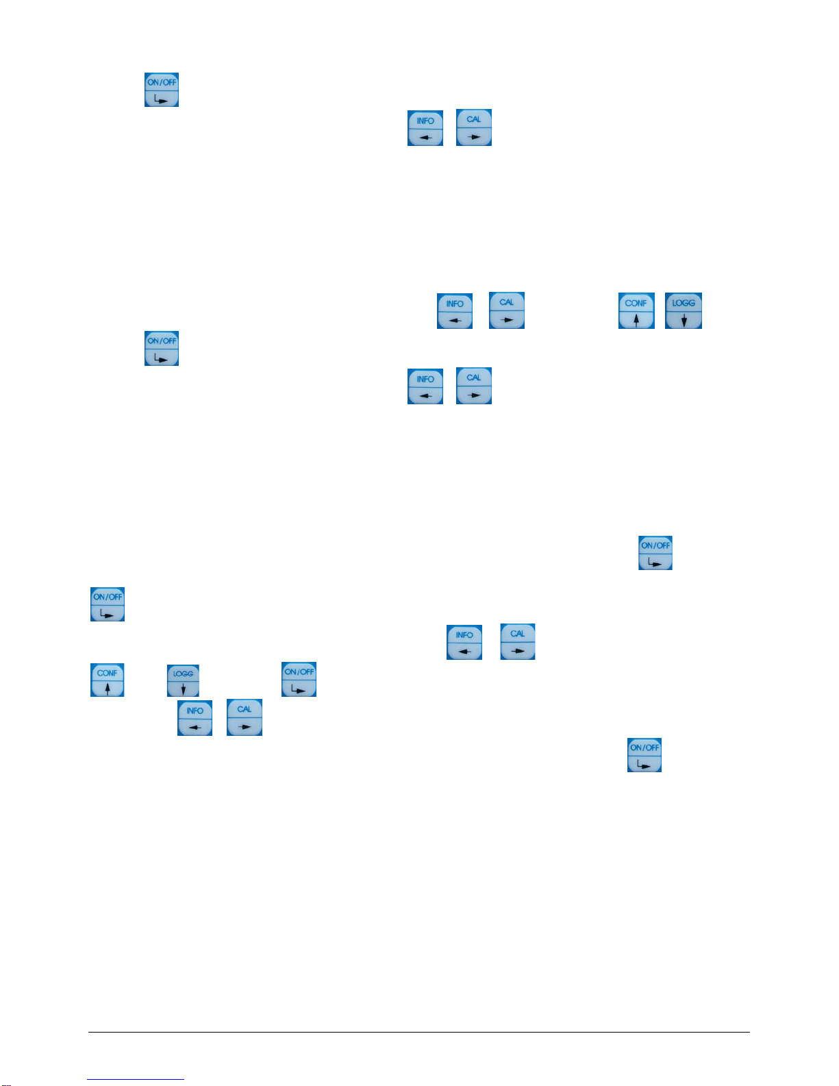
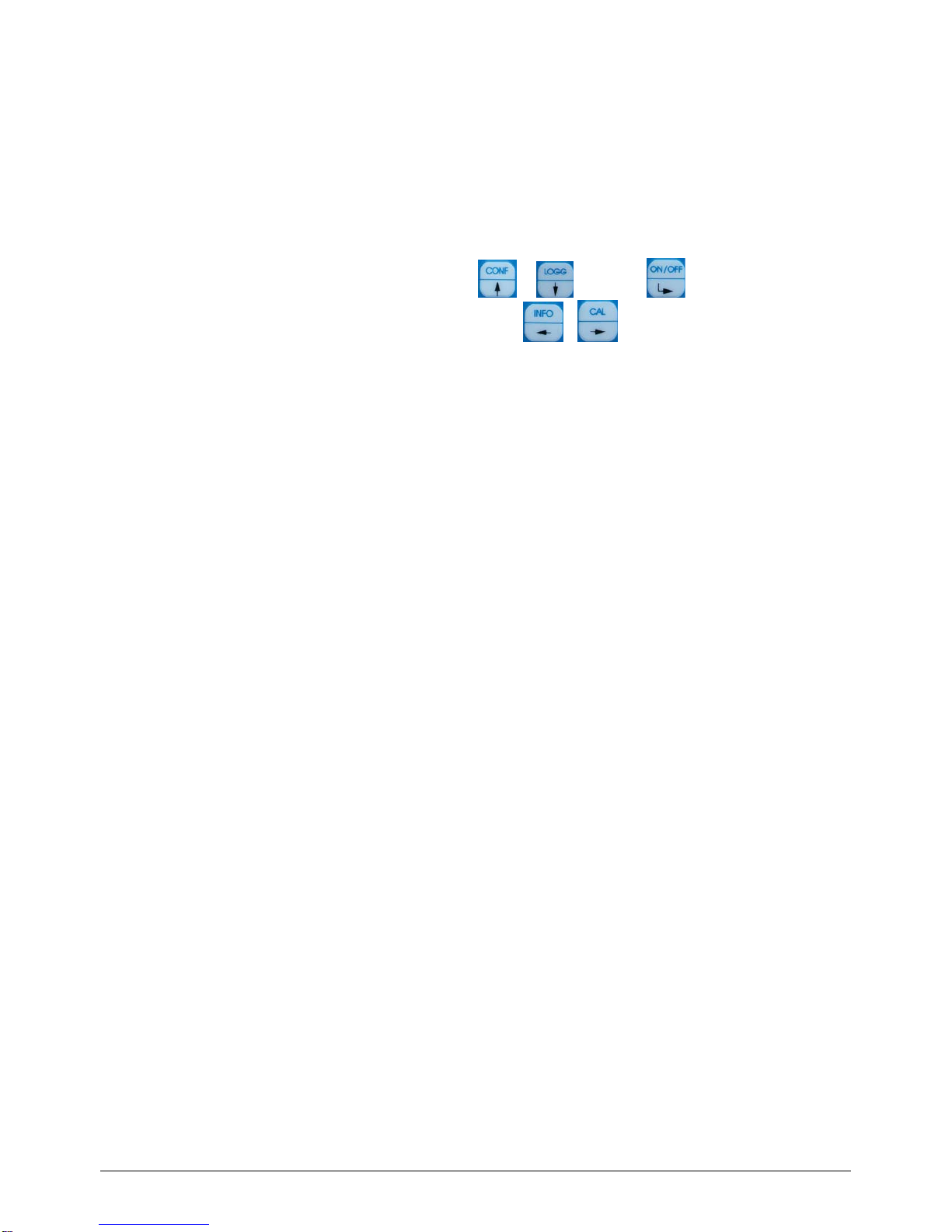
3.1 Operation elements.....................................................................................................................................6
4. Configuration the basic settings “General”...........................................................................................................7
4.1 Configuration Backlight...............................................................................................................................7
4.2 Configuration pass word.............................................................................................................................8
4.3 Configuration clock......................................................................................................................................8
4.4 Configuration language...............................................................................................................................8
4.5 Configuration off time..................................................................................................................................8
4.6 Data logger ..................................................................................................................................................9
5. Info........................................................................................................................................................................10
6. Interface HMG USB.............................................................................................................................................10
7. Maintenance, Disposal........................................................................................................................................10
8. TM 40...................................................................................................................................................................11
8.1Application Fields TM 40...........................................................................................................................11
8.2 Construction TM 40...................................................................................................................................11
8.3 pH-Sensor EGA 142/TM 40......................................................................................................................11
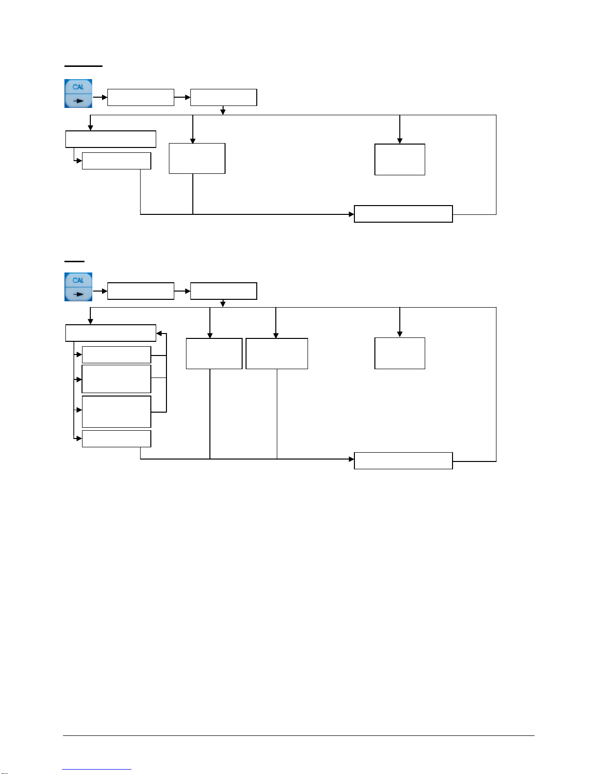
8.4 Menu structure TM 40...............................................................................................................................11
8.5 Calibration pH............................................................................................................................................13
8.5.1 Data input..................................................................................................................................... 13
8.5.2 Settings of the temperature offset............................................................................................... 14
8.5.3 Two-point-Calibration “two point“................................................................................................ 14
8.5.4 Automatic Calibration.................................................................................................................. 14
8.5.5 Calibration error........................................................................................................................... 15
8.6 Calibration Redox......................................................................................................................................15
8.6.1 Data input..................................................................................................................................... 15
8.6.2 Setting of the temperature offset................................................................................................ 15
8.7 Calibration ISE...........................................................................................................................................15
8.7.1 Data input..................................................................................................................................... 15
8.7.2 Settings of the temperature offset............................................................................................... 15
8.7.3 Two-point Calibration „Two point“............................................................................................... 16
8.8 Configuration TM 40..................................................................................................................................16
8.8.1 Configuration of the fix temperature........................................................................................... 16
8.8.2 Configuration of the sensor type.................................................................................................17

9. AM 40...................................................................................................................................................................17
9.1 Application Fields AM 40...........................................................................................................................17
9.2 Construction AM 40...................................................................................................................................17
9.3 Dissolved Oxygen Sensor MF 41-N/AM 40.............................................................................................17
9.4 Menu structure AM 40...............................................................................................................................18
9.5 Calibration oxygen.....................................................................................................................................19
9.5.1 Data input..................................................................................................................................... 19
9.5.2 Settings of the Temperature Offset............................................................................................ 20
9.5.3 Single-Point Calibration „one point“............................................................................................ 20
9.5.4 Automatic Calibration.................................................................................................................. 20
9.5.5 Calibration error........................................................................................................................... 20
9.6 Configuration AM 40..................................................................................................................................21
9.6.1 Configuration of the fix temperature........................................................................................... 21
9.6.2 Configuration of the main value.................................................................................................. 21
10. LF 40....................................................................................................................................................................22
10.1 Application Fields LF 40............................................................................................................................22
10.2 Construction LF 40....................................................................................................................................22
10.3 Conductivity Sensor LTC 0,35/LF 40.......................................................................................................22
10.4 Menu structure LF 40................................................................................................................................22
10.5 Calibration conductivity .............................................................................................................................23
10.5.1 Data input..................................................................................................................................... 23
10.5.2 Settings of the temperature offset............................................................................................... 24
10.5.3 One-point-Calibration „one point“............................................................................................... 24
10.5.4 Automatic calibration „Automatic“............................................................................................... 25
10.5.5 Calibration error........................................................................................................................... 25
10.6 Configuration .............................................................................................................................................25
10.6.1 Configuration of the fix temperature........................................................................................... 25
10.6.2 Configuration of the measuring range „meas. range“ ............................................................... 25
11. Specifications.......................................................................................................................................................26
12. Delivery volume...................................................................................................................................................27
13. Accessories..........................................................................................................................................................27

4/27
1. Safety
This Operating Instructions Manual contains fundamental information that should be observed in connection with the
installation, start-up, operation and maintenance of the instrument in connection with the sensor. Therefore, it is absolutely
vital for the user to read this manual prior to working with it.
User qualification
The meter has been designed for analytical measurements. It is assumed that the user/operator and the maintenance
personnel have the proper professional skills and experience to know the specific properties of analytical measuring
systems, master the safe handling of chemicals, for example, in the maintenance of electrodes/sensors, and can assess
any dangers and risks resulting thereof. The user must ensure that the national legislation and procedures concerning the
maintenance of industrial health and safety standards, the accident preventions and the handling of chemicals are
observed.
Installation and getting started
The perfect functioning and operational safety of the instrument can only be maintained under the climatic conditions
specified in the section "Specification" of this manual. When the instrument is moved from cold to warm surroundings,
condensate may occur and interfere with the functioning of the instrument. In such case, the user should wait until the
temperature of the instrument has adapted to the ambient temperature before using the instrument again.
Use the sensor and interface cables recommended by the manufacturer only. For the sensors and accessories, the
instructions and regulations given in the respective operating instructions manuals and specification sheets will apply. The
instrument can only be operated with the battery specified in the section “Specification”.
Be careful when connecting other instruments (e.g. via interface). Connections with external instruments may cause not
permissible potentials inside the instrument (e.g. connections between GND and earth). These potentials may result in
operational influences or malfunctions in the instrument itself or the external devices connected.
Proper usage
The meter and the sensor are intended for measuring and documentation of analysis parameters. Taking into consideration
the “Specification” paragraph, operating and using the unit for this application is the proper usage. Any application beyond
this and individual modifications or extensions are improper and will lead to loss of entitlement to the warranty. When
connecting the unit with electrochemical sensors, always take into account their life and natural wear as this may result in
malfunctioning of the measuring system and the regulation or control associated therewith. The user must take suitable
measures to limit harmful effects of such malfunctioning.
General safety instructions
The complete meter has been manufactured and tested in accordance with the relevant guidelines and standards for
electronic measuring equipment. It has left the factory in technically unobjectionable condition.
The perfect functioning and operational safety of the instrument and the accompanying components will only be ensured if
the user observes the normal safety precautions as well as the specific safety guidelines stated in the present manual and
in the relevant operating instruction manuals of the components. If there is reason to assume that the instrument can no
longer be employed without a risk, it must be set aside and appropriately marked to prevent further use.
The safety of the user may be endangered, e.g. if the instrument or one of its components
•
shows visible damage,
•
no longer operates as specified,
•
has been stored over a longer period under unsuitable conditions,
•
has been subjected to difficult conditions during transport.
If in doubt, please contact your supplier and sent back the instrument to the manufacturer for repair and maintenance.

5/27
2. Sockets
2 sockets for connecting the sensor and the” Interface HMG USB” are located on the front side of the instrument. Please
use only the delivered original cable for the interface with the PC. For protecting the sockets against moisture and to avoid
corrosion, the sensor should always be connected to the instrument and the “Interface HMG USB” socket should be sealed
by means of the protection cap if it is not in use. The “Interface HMG USB” is not included in the delivery.
Cable Sockets
2.1 Battery
Please open the battery chamber on the back side of the instrument and insert the battery correctly into the chamber.
Battery Chamber
Please use batteries from the type AA, IEC R6, LR6 only. After connecting and inserting the battery, please close the
battery chamber carefully and correctly, to avoid moisture coming inside the device.
If the battery is in low condition, the device shows these with only 1 bar in battery indicator display. A change of the battery
is recommended. If there is no bar in the display, the battery must be changed immediately.
Only for AM 40:
After changing battery or sensor please note the wait time before a new calibration. We recommend a new
calibration after battery change, because the permanent polarisation of the sensor was interrupted by
disconnecting the sensor from the battery.

6/27
3. Button, Display, Menu structure, Password protection
3.1 Operation elements
The instrument features easy operation by means of 5 buttons only and a plain text menu structure.
Button
Open a menu Information Configuration Data logger Calibration On / Off
navigation in the
menu Cursor left Cursor up Cursor down Cursor right selection /
ENTER
input / change
values Cursor left position value +1 position value -1 Cursor right confirm / save
value
By pressing the button “ON/OFF“ the meter switches on. The meter switches off either automatically after a
preset time-out or by long (approximately 3 seconds) pressing the “ON/OFF“ button.
Only for AM 40:
Also when the AM 40 is switched off, the connected O2-Sensor is supplied with the necessary polarisation
voltage and so the system is directly after switching on always ready to measure.
Configuration
Navigation <up>
Calibration
Navigation <right>
Data logger
Navigation <down>
Graphic display
On/Off
Enter
Information
Navigation <left>

7/27
Display
Password protection
The calibration menu (CAL) and the configuration menu (CONF) are password-protected.
The default password for opening these menus is 1.
4. Configuration the basic settings “General”
Open with + password the configuration menu.
Select the menu item you would like to configure.
Backlight
Password
Clock
Language
Off time
Back
4.1 Configuration Backlight
On the device the backlight for display can be switched on or off.
For configuration of the backlight do the following steps:
1. Open menu „general“
2. Select „Backlight“ disable/enable
Select the position you would like to use by using the buttons or .
Press the -button to accept and save the entry.
To cancel the input dialogue without saving the value press + .
Battery bar
display
Main
Measurement value
Second
Measurement value
Date / Time
Fix temperature active
Temperature
Min / Max
Main Measurement value
only LF 40:
Temperature compensation
nLF

8/27
4.2 Configuration pass word
For configuration of the password do the following steps:
1. Open menu „general“
2. Select „Pass word“ and enter your new pass word
3. Retry the new pass word
Select the position you would like to change by using the buttons or and change with or .
Press the -button to accept and save the entry.
To cancel the input dialogue without saving the value press + .
4.3 Configuration clock
For configuration of the clock do the following steps:
1. Open menu „general“
2. Select „clock“ and enter the time and date
Select the position you would like to change by using the buttons or and change with or .
Press the -button to accept and save the entry.
To cancel the input dialogue without saving the value press + .
4.4 Configuration language
For configuration of the language do the following steps:
1. Open menu „general“
2. Select “language“ and enter the language
Select the position you would like to use by using the buttons or
Press the -button to accept and save the entry.
To cancel the input dialogue without saving the value press + .
4.5 Configuration off time
You can set the time when the meter switches off automatically. The data logger will continue to log, if it is set in para 4.6
(Data logger).
To configuration the off time do the following steps:
1. Open menu „general“
2. Select “off time“ and enter the time
Select the position you would like to change by using the buttons or and change with or .
Press the -button to accept and save the entry.
To cancel the input dialogue without saving the value press + .

9/27
4.6 Data logger
The device has an integrated data logger with real-time clock. So it is possible to save the last about 4.000 data sets(date,
time, main measurement value, second measurement value, temperature).
The saved data can be either displayed directly in the device display or transferred by the USB-interface.
To configuration the data logger do the following steps:
1. Open menu „general“
2. Enter the time interval in the menu item „ interval“
Select the position you would like to change by using the buttons or and change with or .
Press the -button to accept and save the entry.
To cancel the input dialogue without saving the value press + .
Data logger Automatic:
If the automatic is switched off, the logger logs only by switched on device. (please note also the off time)
If the automatic is switched on, the logger logs continue. (long time logging)
For correct logger function set the real time clock.
During view the logged data’s the recording is stopped.
Menu structure data logger
measuring-info
next period
1 period
back
back to Measuring
next measuring-info

10/27
5. Info
Menu structure Info
6. Interface HMG USB
For comfortable reading out of the data logger and configuration the device, a download of the software “DinModule” from
http://download.meinsberg.de/en/ is possible. To connected the pocked meter with a PC the as accessory available
“Interface HMG USB“ is needed.
7. Maintenance, Disposal
The meters are almost maintenance-free. In the case of dirtying it is only allowed to clean the outsides with a wet drapery.
Cleaning with aggressive detergent which contains solvents (e.g. acetone) is forbidden. Otherwise damaging of the case
and the plastic foil keyboard may occur. For maintenance and storage of the sensors / electrodes please observe the
corresponding manuals of the sensors / electrodes.
Please send us the old measuring instruments and sensors for disposal. Sensortechnik Meinsberg GmbH takes it back free
of charge and recycles/disposes the electronic scrap in a competent way. Do not dispose your old measuring instruments in
household refuse, this is illegal. Please avoid the disposal at public collecting points.
For more information: http://www.meinsberg.de/en/weee.pdf
MEASURING MODE
MIN/MAX INFO
CAL INFORMATION
RESET MIN/MAX

11/27
8. TM 40
8.1 Application Fields TM 40
The pH/Redox/ISE Meter measures pH,/Redox and ISE-potential and combines the features for mobile application in the
field with the precision and comfort of a laboratory meter with plaint text structure menu, integrated data logging system and
a rugged watertight IP 65 enclosure.
8.2 Construction TM 40
TM 40 / Set comes completely with the accompanying pH-Sensor EGA 142/TM 40 and accessories in a protective case.
This combination operates in accordance with the standardized requirements for determination of pH; electrochemical
probe method acc. EN ISO 10523:2012.
The instrument can be used in any situation where quickly and exactly pH/Redox/ISE-concentration and temperature
should be measured. High measuring accuracy, processor-steered measuring value processing, watertight IP65 case and
the versatility in connection with pH, Redox or ISE Sensors distinguish the TM 40.
The TM 40 has an automatic temperature compensation for the pH measurement as well as an adjustable reference
temperature with measurements without temperature sensor. For calibration the automatic or manual calibration routine
can be used.
By connection of a Redox sensor the TM 40 displays the measured Redox potential (to the Ag/AgCl-relation electrode) and
the temperature-compensated calculation of the Redox potential referenced on the standard-hydrogen electrode to DIN
38404.
8.3 pH-Sensor EGA 142/TM 40
In the standard version the meter TM 40 comes with the pH / temperature combination electrode EGA 142/TM 40. This
electrode features general application for laboratory and field. Its built-in temperature probe Pt 1000 enables simultaneous
measurement of pH and temperature as well as automatic temperature compensated pH measurement. Obviously special
electrodes (pH combination electrodes, redox combination electrodes or electrodes supplied from other manufacturers with
BK plug) can be used in connection with TM 40. The isopotential point (25deg) of the used electrodes must be pH 7.
Platinum combination electrodes with Ag/AgCl reference system with 3 mol/l KCl electrolyte are recommended for redox
potential measurements.(i.e. EMC 133/TM 40).
8.4 Menu structure TM 40
Menu structure Calibration
pH
pass word
back
Calibration
CAL INFORMATION
two point
temp.offs.
input
Asymmetrie
slope
back
automatic

12/27
Redox
ISE
pass word
back
Calibration
CAL INFORMATION
two point
temp.offs.
input
slope
meas.val.
input.val.
back
pass word
back
Calibration
CAL INFORMATION
temp.offs.
input
Offset

13/27
Menu structure Configuration
8.5 Calibration pH
Open with + password the calibration menu.
All kinds of calibration method will be displayed. Choose now your method.
Take note of temperature compensation for all calibration methods. This means, if measured values are compensated by
temperature measurement, the associated temperature sensor must also be dipped into the calibration medium to be able
to determine the exact temperature.
Carefully rinse electrode with distilled/deionized water after each measurement to avoid carrying off of the measuring
medium and sluggish measurement.
The sensor will be dipped in the buffer solution. Wait until the value is stabilised.
8.5.1 Data input
Data input stands for the input of the specific values of the connected sensor, for example as determined at the laboratory
before.
asymmetry
slope
back
Select the corresponding calibration value whose settings you want to change. An input dialogue will now enable you to
change the values within corresponding limits. If you exceed these you will get an error message to prompt you to enter a
value within the fixed limits.
Select the position you would like to change by using the buttons or and change with or .
back
data logg.
back
Intervall
automatic
temperature
back
fixed temp.
temp.-value
sensortype
pH
Redox
general
clock
backlight
password
language
off time
back
pass word
Configuration
ISE

14/27
Press the -button to accept and save the entry.
To cancel the input dialogue without saving the value press + .
8.5.2 Settings of the temperature offset
This menu item enables you to set a temperature value offset. For this purpose open the menu item “temp. offs.”. Now, an
input dialogue will be displayed which facilitates the setting. The offset can be positive or negative.
Select the position you would like to change by using the buttons or and change with or .
Press the -button to accept and save the entry.
To cancel the input dialogue without saving the value press + .
8.5.3 Two-point-Calibration “two point“
Calibrate the sensor at two separate points using two different defined calibration solutions or known set point values. The
calibration points are supposed to include the measuring range or the measured values to be expected, respectively. You
can choose any sequence of the calibration solutions or set point values.
At first, you will be prompted to dip the sensor into the first calibration medium. After this step press to accept the
dialogue. Now, the currently measured value will be displayed. After the measured value has attained a stable state, press
to accept the dialogue. You will now be prompted to enter the associated set point value.
Select the position you would like to change by using the buttons or . Adjust the corresponding position with
(+1) or (-1). Press the -button to accept and save the entry. To cancel the input dialogue without saving
the value press + . The next dialogue field will now prompt you to dip the sensor into the second calibration
medium. After you have accepted this, the currently measured value will, again, be displayed. Press again to accept
the stabilised measured value, before you will be prompted to enter the associated set point value.
As a result, you will now be given the new calibration values that will be save in the device.
8.5.4 Automatic Calibration
The automatic calibration of the pH measurement is a two-point type and requires knowledge of what buffer solution group
you want to use. The TM 40 offers the following buffer solution groups for calibration:
NBS standard buffer solution as per DIN 19266: pH value at 25 °C 1.68 / 4.01 / 6.86 / 9.18 / 12.45
Technical buffer solution as per DIN 19267: pH value at 25 °C 1.09 / 3.06 / 4.65 / 6.79 / 9.23
Knick/Mettler-Toledo/Ingold buffer solution: pH value at 25 °C 2.00 / 4.01 / 7.00 / 9.21
Laboratory buffer solution: pH value at 25 °C 2.00 / 4.01 / 6.98 / 8.95 / 11.88
You must take a choice in the first dialogue box of the used buffer solutions. For further conditions and tips, please refer to
the sensor specifications.

15/27
A subsequent dialogue will prompt you to dip the sensor into the first buffer solution. Press to confirm. Now, the
current measured value will be displayed. After the display shows a stabilised value, confirm this. Now, the same procedure
as for the first buffer solution will follow (dip sensor into buffer solution 2, wait for value stabilisation) for the second one.
As a result, you will now be given the new calibration values that will be save in the device.
8.5.5 Calibration error
In the TM 40 predefined ranges for the calibration values are stored. If the determined calibration value is out of the range
the message !Out of limit! appears in the calibration information CAL INFORMATION. The determined calibration value
will be stored nevertheless, so that the measuring and controlling is secured. In this case a new calibration or a replace of
the sensor is necessary.
8.6 Calibration Redox
8.6.1 Data input
This menu item enables you to set a Redox value offset. Please see also para 8.4 Redox.
8.6.2 Setting of the temperature offset
This menu item enables you to set a temperature value offset.
Same procedure as pH temperature offset at para 8.5.2.
8.7 Calibration ISE
8.7.1 Data input
Data input stands for the input of the specific values of the connected sensor, for example as determined at the laboratory
before.
Select the corresponding calibration value whose settings you want to change by. An input dialogue will now enable you to
change the values within corresponding limits. If you exceed these you will get an error message to prompt you to enter a
value within the fixed limits.
slope
meas.val.
input. Val.
back
Select the position you would like to change by using the buttons or and change with or .
Press the -button to accept and save the entry.
To cancel the input dialogue without saving the value press + .
8.7.2 Settings of the temperature offset
This menu item enables you to set a temperature value offset.
Same procedure as pH temperature offset at para 8.5.2.

16/27
8.7.3 Two-point Calibration „Two point“
Calibrate the sensor at two separate points using two different defined calibration solutions or known set point values. The
calibration points are supposed to include the measuring range or the measured values to be expected, respectively. You
can choose any sequence of the calibration solutions or set point values.
At first, you will be prompted to dip the sensor into the first calibration medium. After this step press to accept the
dialogue. Now, the currently measured value will be displayed. After the measured value has attained a stable state, press
to accept the dialogue. You will now be prompted to enter the associated set point value.
Select the position you would like to change by using the buttons or . Adjust the corresponding position with
(+1) or (-1). Press the -button to accept and save the entry The next dialogue field will now prompt you
to dip the sensor into the second calibration medium. After you have accepted this, the currently measured value will, again,
be displayed. Press again to accept the stabilised measured value, before you will be prompted to enter the
associated set point value. As a result, you will now be given the new calibration values that will be save in the device. To
cancel the input dialogue without saving the value press + .
8.8 Configuration TM 40
Open with + password the configuration menu.
Select the menu item you would like to configuration.
data logg
temperature
sensortype
general.
back
8.8.1 Configuration of the fix temperature
For calculating the analysis parameter pH a temperature compensation is always necessary.
For that the temperature of the measuring and of the calibration fluid must be measured or a fix temperature must be
configured. If the fix temperature is activated this will be used for the temperature compensation. In this case the message
Fix appears in the right upper display corner.
For configuration the fix temperature do the following steps:
1. open the menu „temperature“
2. activate / deactivate the fix temperature in the menu item „fixed temp.“
3. enter the fix temperature value in the menu item „ temp.-value“
Select the position you would like to change by using the buttons or . Adjust the corresponding position with
(+1) or (-1). Press the -button to accept and save the entry. To cancel the input dialogue without saving
the value press + .

17/27
8.8.2 Configuration of the sensor type
The TM 40 can be connected with pH, ORP or ISE electrodes. The used sensor type has to be configured in the device.
For configuration of a sensor type do the following steps:
1. open menu „sensortype“
2. select the type
pH
Redox
ISE
Select the position you would like to use by using the buttons or . Press the -button to accept and save
the entry. To cancel the input dialogue without saving the value press + .
9. AM 40
9.1 Application Fields AM 40
The Oxygen Meter measures dissolved oxygen in accordance with the German standard methods for the examination of
water, waste water and sludge DIN EN ISO 5814 : 2013 and combines the features for mobile application in the field with
the precision and comfort of a laboratory meter. The meter is the ideal choice for determination of the oxygen content in
surface water, sewage and for application in wastewater treatment. AM 40 features simultaneous measurement of oxygen
and temperature, high measuring accuracy, multi function display, easy air calibration, integrated data logging system and a
rugged watertight IP 65 enclosure.
9.2 Construction AM 40
AM 40/Set comes completely with the accompanying dissolved oxygen sensor MF 41-N/AM 40 and accessories in a
protective case. This combination operates in accordance with the standardized requirements for determination of
dissolved oxygen; electrochemical probe method acc. ISO 5814 : 1990 resp. German version DIN EN ISO 5814 : 2013.
The instrument in connection with the sensor indicates the mass concentration of dissolved oxygen in aqueous solutions in
mg/l and the oxygen saturation index in percent saturation as well as the relevant temperature simultaneously.
9.3 Dissolved Oxygen Sensor MF 41-N/AM 40
The MF 41 sensor is based upon the Clark principle as a polarographic sensor containing a Pt cathode as the working
electrode and an Ag/AgCl anode as the counter electrode. Both electrodes inclusive the electrolyte are separated from the
medium by a membrane. The membrane is permeable only to molecular oxygen, so that liquids, ions and solids are not
able to reach the electrochemical cell. At a polarisation voltage of about 700 mV between platinum cathode and Ag/AgCl
anode a current occurs. The oxygen molecules diffused through the membrane are reduced to hydroxyl ions (OH-) at the
cathode. At the anode, the equivalent amount of silver is oxidized to AgCl. This causes a current depending on the oxygen
partial pressure of the analysed medium.
The oxygen sensor consists of a shaft and a basic body inclusive the electrode system and the membrane head. The basic
body made of stainless steel contains the platinum cathode, the Ag/AgCl anode and a built-in temperature sensor Pt 1000.
The membrane head has an integrated polymeric membrane and is equipped with an optimally designed multi-layer
membrane using a very durable and dirt repelling material. This features high accuracy and reliability as well as long time
intervals for maintenance of the sensor.

18/27
9.4 Menu structure AM 40
Menu structure Calibration
Fix cable with plug
Basic body
Membrane head
Shaft
Password
back
Calibration
CAL INFORMATION
one point
input
slope
B<20°C
B>20°C
back
automatic
temp.Offs.

19/27
Menu structure Configuration
9.5 Calibration oxygen
Open with + password the calibration menu.
All kinds of calibration method will be displayed. Choose now your method.
Please take note for all calibration method the temperature compensation.
9.5.1 Data input
Data input stands for the input of the specific values of the connected sensor, for example as determined at the laboratory
before.
Select the corresponding calibration value whose settings you want to change. An input dialogue will now enable you to
change the values within corresponding limits. If you exceed these you will get an error message to prompt you to enter a
value within the fixed limits.
Select the position you would like to change by using the buttons or and change with or .
Press the -button to accept and save the entry.
To cancel the input dialogue without saving the value press + .
data logg.
back
intervall
automatic
temperature
back
fixed temp.
temp.-value
%
mg/l
general
clock
backlight
password
language
off time
back
pass word
Configuration
Main value

20/27
9.5.2 Settings of the Temperature Offset
This menu item enables you to set a temperature value offset. For this purpose open the menu item “temp.offs”. Now, an
input dialogue will be displayed which facilitates the setting. The offset can be positive or negative.
Select the position you would like to change by using the buttons or and change with or .
Press the -button to accept and save the entry.
To cancel the input dialogue without saving the value press + .
9.5.3 Single-Point Calibration „one point“
Calibrate the measuring signal at this one point using a defined calibration solution or a known set point value, e. g.
determined by a separate method or by means of another laboratory/field instrument. At first, you will be prompted to dip
the sensor into the corresponding calibration medium.
After this step press . to accept the dialogue. Now, the currently measured value will be displayed. After the
measured value has attained a stable state, accept the dialogue again by pressing . You will now be prompted to
enter the set point value.
Select the position you would like to change by using the buttons or and change with or .
Press the -button to accept and save the entry. To cancel the input dialogue without saving the value press +
.
As a result, you will now be given the new calibration values that will be save in the device.
9.5.4 Automatic Calibration
The automatic calibration of the oxygen content measurement is a single-point calibration in the ambient air up to 102%.
At first, you will be prompted to dip the sensor into the corresponding calibration medium (outside air).
After this step press . to accept the dialogue. Now, the currently measured value will be displayed. After the
measured value has attained a stable state, accept the dialogue again by pressing .
As a result, you will now be given the new calibration value that will be save in the device.
9.5.5 Calibration error
In each device predefined ranges for the calibration values are stored. If the determined calibration value is out of the range
the message !Out of limit! appears in the calibration information CAL INFORMATION. The determined calibration value
will be stored nevertheless, so that the measuring and controlling is secured. In this case a new calibration or a replace of
the sensor / sensor part (membrane head, electrolyte) is necessary.
This manual suits for next models
2
Table of contents
Other Sensortechnik Meinsberg Measuring Instrument manuals
Popular Measuring Instrument manuals by other brands

Sierra
Sierra InnovaSonic 207i BACnet instruction manual

Coster
Coster IET 7143 C1 Wiring diagram

Hioki
Hioki 3196 manual

Seametrics
Seametrics iMAG 4700r instructions

Endress+Hauser
Endress+Hauser cerabar S operating instructions

MADDALENA
MADDALENA microCLIMA/SENSOSTAR 2+ MSH Installation and operating instructions