Sensortechnik Meinsberg LF 39 User manual
Edition July 2002
Operating instructions
Meinsberg
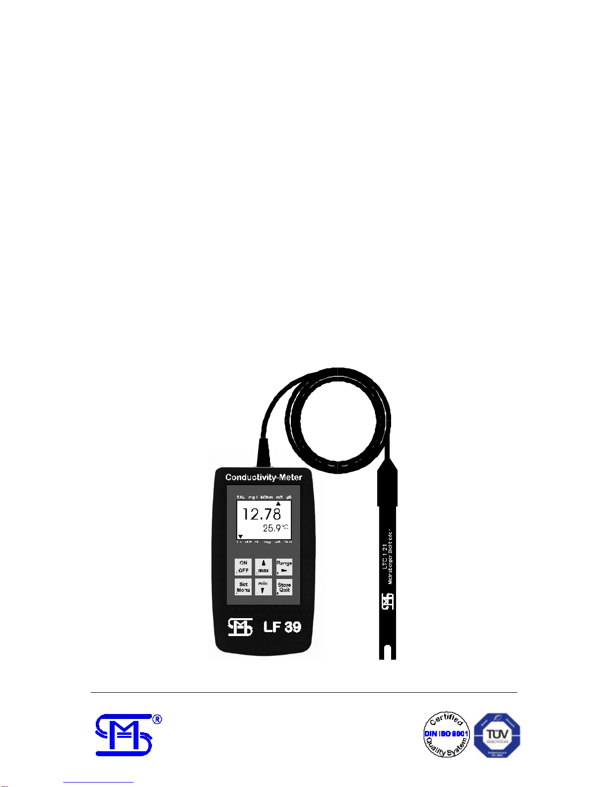
Conductivity Meter
LF 39
Sensortechnik Meinsberg GmbH
Fabrikstraße 69, OT Meinsberg Phone : + 49 34327 623-0
D-04720 Ziegra-Knobelsdorf Fax : + 49 34327 623-79
-1-
Please read this information carefully before putting the device into service
Operation and Maintenance Guidelines:
a.) Change of batteries:
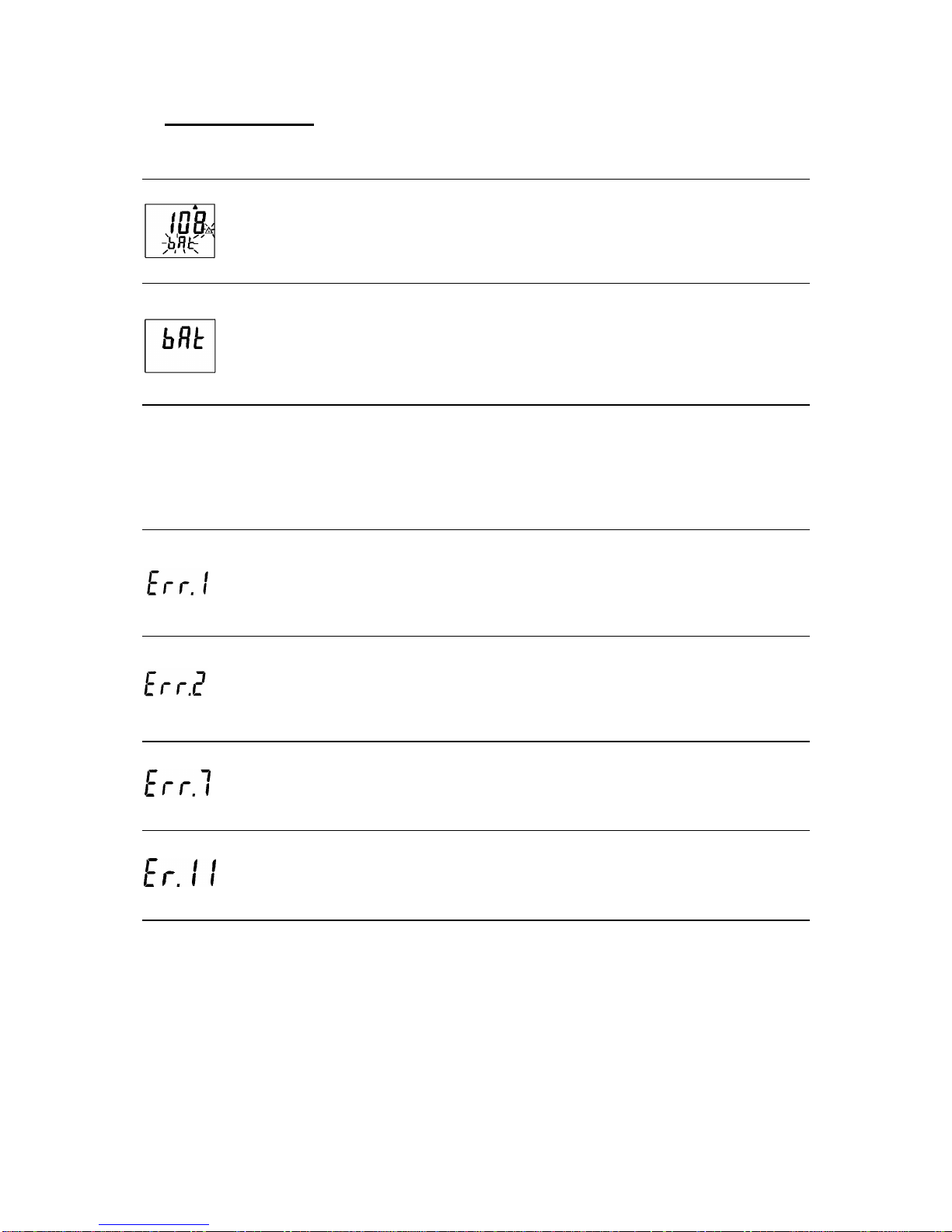
If you see the state of charge indication and in the lower display ´bAt´, the battery is nearly discharged.
The instrument is still operable for some time.
The sign ´bAt´ in the upper display shows that the battery is totallydischarged. The instrument is not more
operable.
Remove the battery if you do not use the instrument for a longer time!
b.) The instrument and the sensor/electrode has to be used carefully and in accordance withthe specifications
in the short-operating instructions. Ensure that all electrical terminations and connections are kept clean
and dry.
c.) To disconnect the temperature sensor do not pull the cable, but use the plug. Ensure to connect plug and
socket inthe right direction; you do not need high force for connection.
d.) Operation with Power Supply LF 39-N:
Use the plug mains supply unit N 10 from the manufacturer only.
Before connecting the unit ensure that the mains voltage stated on the delivered plug mains supply unit is
identical with your mains voltage.
Safety Guidelines:
This device has been built and tested according to the safety standards for electronic measuring
instruments. The perfect functioning and operational safety of the instrument can only be ensured if the
user observes the normal safety precautions as well as the specific safety guidelines stated in the
present operating instruction.
1. The perfect functioning and operational safety of the instrument can only be maintained under the climatic
conditions specified in the "Technical data" section of these operating instructions.
2. When the instrument is moved from cold to warm surroundings, condensate may occur and interfere with
the functioning of the instrument. In such case, the user should wait until the temperature of the instrument
has adapted to the ambient temperature before usingthe instrument again.
3. Be careful with the connection of other instruments (e.g. via interface).
Wrong connections to external instruments may cause not permissible potentials inside the instrument
(e.g. connections between GND and earth). These potentials may result in malfunctions and damages of
the instrument or the external instruments.
Operation of the instrument with a damaged plug mains supply unit (e.g. short circuit between main
voltage and output voltage) may cause hazards for the user because live parts will become exposed!
4. If there is reason to assume that the instrument can no longer be employed without a risk, it must be set
aside and appropriately marked to prevent further use.
The safety of the user may be endangered, e.g., if the instrument
-shows visible damage,
-no longer operates as specified,
-has been stored over a longer period under unsuitable conditions,
-has been subjected to difficult conditions during transport.
If in doubt, the instrument should as a rule be sent back to the manufacturer for repair and maintenance.

-2-
Contents
1. Application
2. Construction
2.1. Conductivity Cell
2.2. Conductivity Meter
3. Operation
3.1. Putting into operation
3.2. Selection of the measuring parameters
3.3. Selection of the measuring ranges
3.4. Storage of the maximum and minimum values
3.5. Operation mode (configuration menu)
3.6. Measurement
3.7. Maintenance of the conductivity cell
4. Trouble shooting
5. Technical data
6. Delivery volume, accessories and special versions

-3-
1. Application
The model LF 39 is ideal for lab, field and industrial work. The meter features high accuracy,
rugged plastic case, microprocessor-controlled processing and a wide range of application in
conjunction with the conductivity cell with graphite electrodes and built-in temperature probe.
The LCD displays low battery warning. The LF 39 offers different modes for automatic
temperature compensation, selection of the reference temperature and measurements
without temperature compensation. Measurement of the solution resistance, the salinity and
the total dissolved solids (TDS) expand the application range of the LF 39.
2. Construction
2.1. Conductivity Cell
The Conductivity Cell 1/21 has a fixed cable connection to the meter with a length of 1.35 m
and is ideal for general applications in laboratory and field. Two special graphite electrodes
sealed in epoxy feature high mechanical stability, easy purification and low maintenance. A
temperature sensor with low response time is integrated in the cell for automatic temperature
compensation and parallel measurement.
2.2. Conductivity Meter
Display 1Main display: conductivity (mS, µS), resistance
(kΩ), TDS (total dissolved solids mg/l), salinity
(SAL) resp. user’s instructions
2Display elements for maximum and minimum
values
3Display of the dimensions for the measuring
values
4Warning-signal (low battery warning)
5Lin/nLF: shows the selected mode for automatic
temperature compensation
6 %/K: Adjustment of the temperature coefficient
7 1/cm: Adjustment of the cell constant
8Secondary display: measured temperature resp.
user’s instructions
-4-
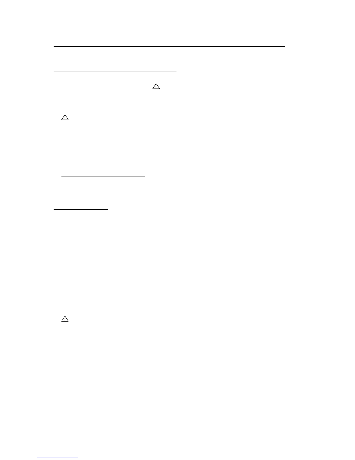
Control elements 10 ON/OFF switch
11 min/max during measurement:
Momentarily press the key:
displays the max. and min. measured values
Depress the key for 2 s:
Erasure of the stored values
min/max during Set/menu mode:
setting or changing of numerical values
12 Range:for conductivity measurement only
Depress the key for 2 sec.:
Switch-over of measuring range selection (automatically or
manually)
Momentarily press the key:
in connection with manual measuring range selection
Switch-over to the next lower meas. range resp. from the
lowest possible to the highest meas. range
13 Set/Menu:
Momentarily press the key (set):
Change between the measuring parameters
Depress the key for 2 sec. (menu):
makes active the configuration menu
14 Store/Quit:
Measurement:
actual measuring value is stored and frozen. ('HLD' in display)
Set/menu: confirmation of input; return to measurement
Sockets
20 Interface: Connection of the isolated
interface adapter (LF 39-D only)
21 Measuring Cell: Cable gland for fixed cable
connection
3. Operation
3.1. Putting into operation
Before first operation insert a new battery IEC6F22 or replace the old battery (low battery
warning and bAt). The battery compartment is down on the back side. Take care for
polarity!
Meter and electrode are ready for measurement. Take notice of the descriptions in section
3.7. (Maintenance of the conductivity cell).
Immediately after switching on the meter the parameters cell constant, mode of temperature
compensation and measuring range selection stored with the last measurement are
displayed.
-5-
3.2. Selection of the measuring parameters
For selection of the measuring parameters momentarily press the key
4
Set
Menu
. The measuring value of
the actual parameter is shown in the main display and the accompanying dimension is given by the
arrow to the upper part of the display. In the secondary display the actual temperature is shown.
µS : Measurement of the electric conductivity in µS/cm
mS : Measurement of the electric conductivity in mS/cm
kOhm : Measurement of the solution resistance in kΩ•cm
mg/l : Calculation of the total dissolved solids (TDS) in mg/l
SAL : Calculation of the salinity
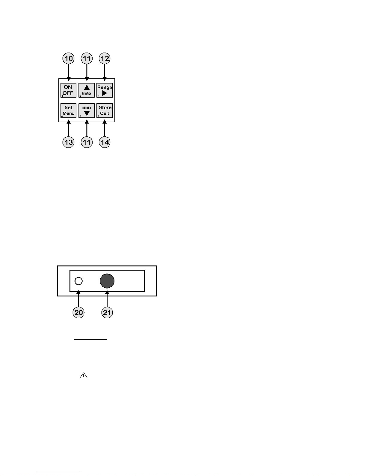
3.3. Selection of the measuring ranges
The LF 39 features conductivity measurement in four different ranges.
0.0 ... 200.0 µS/cm
0... 2000 µS/cm
0.00 ... 20.00 mS/cm
0.0 ... 200.0 mS/cm
For switch on or off of the automatic measuring range selection
depress the key
Range
5for 2 sec. The activated function is shown in
the display (Auto on/off) until the key
Range
5is let off. Momentarily
depressing the key Range
5changes into the next higher measuring
range if manual measuring range selection is activated (Auto off). If already the highest
measuring range was switched on, the meter is changing into the lowest possible range. The
accompanying dimensions are given by the arrow to the upper part of the display.
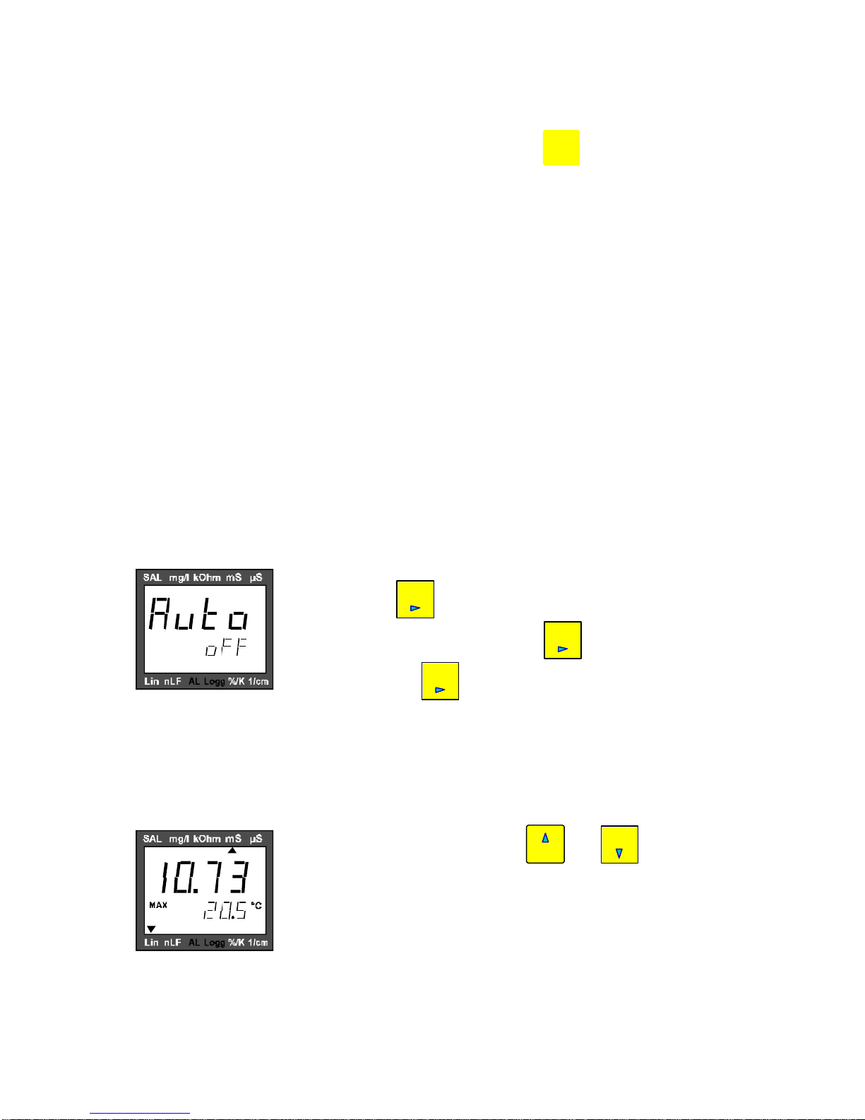
3.4. Storage of the maximum and minimum values
Momentarily depressing the key
max
2
or min
5displays the
measured maximum or minimum value in the main display. The
secondary display shows simultaneously the accompanying
temperature which was measured at the maximum or the minimum
value of the actual measuring parameter.

-6-
With a momentary press on the key
4
Set
Menu
it is possible to change between the maximum and
minimum values of the single measuring parameters (look at point 3.2. Selection of the
measuring parameters). Obvious this function is given also for measuring parameters which
were not activated during the measurement. Erasure of the stored maximum or minimum
values is done with depressing the key
max
2
or
min
5
for about 2 seconds.
3.5. Operation mode (Configuration menu)
For configuration of the meter depress the key
4
Set
Menu
for 2 seconds .
Change between the functions by pressing the
4
Set
Menu
key and select the parameters resp.
adjustments with the keys
max
2
or
min
5
. Leave the configuration menu by pressing the key
6
Store
Quit
and all activated changes will be stored.
‘t.Cor’: Setting of the temperature compensation function
max
2
Lin : Linear temperature compensation with adjustable
temperature coefficient
nLF: non-linear temperature compensation for natural water
according to DIN EN 27888.
min
5
off : measurement without temperature compensation
The non-linear temperature compensation for natural water acc. to DIN EN 27888 is used for
the measuring parameter (TDS). To measure salinity the instrument automatically switches
to the non-linear temperature compensation according to IOT (reference temperature 15°C).
The conductivity value compensated with the selected temperature function is used for all
other calculated measuring parameters (look at point 3.2.).
‘t.Lin’ : Adjustment of the temperature coefficient (for linear temperature
compensation only)
max
2
0.300..3.000 :
min
5
Set temperature coefficient in %/K for the
used linear temperature compensation
(Please note, the temperature coefficient
depends from the selected reference
temperature).

-7-
‘t.rEF’: Selection of the reference temperature
max
2
20 °C : reference temperature 20 °C
min
5
25 °C : reference temperature 25 °C
‘C.tdS’: Adjustment of the determined TDS-factor
max
2
0.40..1.00 : TDS-factor
min
5
The TDS-factor depends from the composition of the
measured medium.
‘CELL’: Adjustment of the specific „cell constant“
max
2
0.800..1.200 : „cell constant“ in cm-1
min
5
Natural ageing processes and deposits on the electrodes
result in changes of the cell constant. The cell constant of the
conductivity cell is determined in conductivity standard solution
at a temperature of 25 °C (look at point 3.7
Maintenance of the conductivity cell)
Prior to despatch the „cell constant“ of the fixed connected conductivity cell is adjusted in
conjunction with the meter to the value 1.000.
'Unit': Selection of the dimension of the temperature °C /°F
max
2
°C:All temperature values in degree Centigrade
min
5
°F:All temperature values in degree Fahrenheit

-8-
‘OFFS’ : Temperature calibration
The temperature calibration makes it possible to correct systematic errors caused by
tolerances of the temperature probes in comparison with other temperature measuring
instruments. This single point calibration will only shift the displayed temperature value to the
measured temperature with an added offset value.
max
2
-2.0... 2.0 °C: Adjustment of the offset value
resp. displayed temperature = measured
-3.6... 3.6 °F: temperature -offset
min
5
off: without offset compensation (= 0.0 °C)
'P.oFF': Selection of the time for automatic switch-off
max
2
1...120:Time for switch-off in minutes. If no key is
pressed and no data transmission is
active, the instrument is switched off
automatically after the adjusted time.
min
5
off: automatic switch-off is not active (continuos
operation e.g. operation with mains supply unit)
3.6. Measurement
LF 39 works in the selected operation mode (look at point 3.2. Selection of the measuring
parameters). Immerse the conductivity cell into measuring solution and wait until the
measurement value is stabil. Pay attention to efficient mixture of the measuring solution and
temperature equilibrium.
Carefully rinse the conductivity cell with distilled/deionized water after each measurement to
avoid carrying off of the measuring medium and sluggish measurement.
Pay attention to description about storage and cleaning of the electrode in the point 3.7.
(Maintenance of the conductivity cell).
3.7. Maintenance of the conductivity cell
Conductivity cells do not normally age. However they can be damaged by excessive
temperatures, or certain liquids, e.g. strong acid and alkaline solutions or organic solvents.
Cleaning
-Treat the electrodes with care to avoid mechanical damage or/and shortening of the life time.
-Grease or oil contamination may be removed by soaking the electrodes in warm soapy water.
-Lime or hydroxide deposits may be removed using 10 % acetic acid.
-After any cleaning process, the conductivity cell should be rinsed in deionized/distilled water.
-Rinse and storage of the cell with deionized/distilled water before measurement reduces the response
time.
-Ensure that all electrical terminations and cable connections are kept clean and dry !

-9-
Calibration procedure
Maintenance of the meter contains calibration, cleaning of the cell, checking of the cell
constant and adjustment of the new determined cell constant (look at point 3.5). The
adjustment of the conductivity meter is effected by setting of the cell constant. The
appropriate calibration interval period depends on the accuracy of the measurements and the
conditions of application. The procedure for carrying out the calibration is laid down in the
European Standard EN 27888 (Determination of Electric Conductivity).
-Select the Conductivity Standard Solution in accordance with the considered measuring range. Please
note that standard solution do have a finite shelf life.
-Before calibration rinse the conductivity cell several times and thoroughly first with deionized/distilled
water and than with some standard solution.
-Stabilise the temperature of the measuring vessel with standard solution and conductivity cell at 25 °C.
For routine measurements it is sufficient to observe a tolerance of ±0.5 K.
-Set the LF 39 into operation, select the operation mode (measuring parameter) conductivity measurement
mS or µS without temperature compensation, adjust the reference temperature 25 °C and use the lowest
measuring range in accordance with the used standard solution (look at point 3.5.) ; notice the present
cell constant.
-Wait until the measurement value is stabil. Pay attention to efficient mixture of the standard solution and
temperature equilibrium. Calculate the new „cell constant“ specifically determined in connection with the
used LF 39.
new cell constant conductivity of the standard solution
measured conductivity value present adjusted cell constant=•
-Adjust the new determined „cell constant“ in accordance with point 3.5. (max. deviation±0,05 from the
present constant or the constant determined at the last calibration)
-10 -
4. Trouble Shooting
Error message Cause Action
battery nearly discharged, operation change battery
will be possible only for a short time
-battery discharged change battery
-damaged mains supply unit change mains supply unit,
if error is not removed
-> send back to the manufacturer
no display, -battery discharged change battery
instrument does -damaged mains supply unit check/change mains supply unit
not react upon -system error disconnect the battery or the mains
key operation, no unit, wait a moment, connect battery
measurement again
-damaged instrument -> send back to the manufacturer
-values exceeding check possibilities for measuring
measuring range values outside the specified
measuring ranges?
-damaged cell/cable -> send back to the manufacturer
-values falling below check possibilities for measuring
measuring range values outside the specified
measuring ranges?
-damaged cell/cable -> send back to the manufacturer
-system error switch on again, if error is not
removed,
-> send back to the manufacturer
-value could not be calculated a measuring value required for
calculation is false (overflow)

-11 -
5. Technical data
Measuring parameters mS/cm ; µS/cm ; kΩ•cm ; mg/l ; SAL
Measuring ranges 0.0 ... 200 µS/cm
0... 2000 µS/cm
0.00 ... 20.00 mS/cm
0.0 ... 200.0 mS/cm
0.005 ... 100.0 kΩ
0... 1999 mg/l
SAL 0.0 ... 70.0
-5 ... 100 °C
Accuracy (instrument) conductivity, resistance, TDS and salinity :
±1 % FS in the ranges 0 ... 200 µS/cm,
0 ... 2000 µS/cm and 0 ... 20 mS/cm
±2 % from meas. value in the range
0 ... 200 mS/cm
temperature :
±0,2 % from meas. value ±0,3 K ±1 digit
Cell constant specifically in conjunction with instrument ;
adjustable 0.8 ... 1.2 cm-1
Reference temperature selectable 20 °C / 25 °C
Temperature compensation 1. linear compensation with adjustable
temperature coefficient 0.3 ... 3.0 % / K
2. non-linear compensation for natural water acc.
to DIN EN 27888
3. without compensation
Display 2 four digit LC displays (height: 12.4
resp. 7 mm)
Ambient temperature 0 ... 50 °C
Relative humidity 0 ... 95 % (non-condensing)
Storage temperature (instrument) -20 ... 70 °C
Power supply 9 V battery type IEC 6F 22
LF 39-N: additionally with mains supply unit
Interface LF 39-D: additionally with isolated interface
adapter (optional accessory) for RS-232
connection to a PC
EMC in accordance with regulation 89/336/EWG
(additional fault < 1%)
Cell connection fixed cable connection 1.35 m

-12 -
Dimensions instrument 142 x 71 x 26 mm (L x W x D)
Conductivity cell Two-electrode cell with built-in temperature probe
electrode material : special graphite
shaft material : polysulfon
dimensions : ∅12 mm, length 120 mm
temperature range: -5 ... 80 °C
cell constant : 1 cm-1 ±20 %
6. Delivery volume, accessories and special versions
6.1. Delivery volume
Meinsberg Conductivity Meter LF 39/Set
-instrument LF 39 with conductivity cell LTC 1/21
-50 ml Conductivity Standard Solution 0.1 N KCl (12.9 mS/cm at 25 °C)
-Operating instructions
-battery 9 V type IEC 6F 22
-measuring case with instrument, cell and standard accessories
6.2. Optional accessories
Recommended optional accessories :
-Conductivity Standard Solution 0.1 N KCl (12.9 mS/cm at 25 °C) 1 bottle 250 ml
-Conductivity Standard Solution 0.01 N KCl (1.41 mS/cm at 25 °C) 1 bottle 250 ml
-Conductivity Standard Solution 0.001 N KCl (147 µS/cm at 25 °C) 1 bottle 250 ml
6.3. Special versions
LF 39-N : In addition to battery operation the LF 39 can be connected via special
mains socket (internal pin ∅1.9 mm) to the plug mains supply unit N 10.
Use the plug mains supply unit N 10 from the manufacturer only.
LF 39-D : Direct connection to RS-232 interface of a PC via isolated interface adapter
D 10 with a mono plug 3.5 mm. Standard software is available for transfer,
record and storage of measuring values. Operation of LF 39 with
communication package D 10 is descripted in a supplement of the
operating instructions.
Table of contents
Other Sensortechnik Meinsberg Measuring Instrument manuals

Popular Measuring Instrument manuals by other brands


Mirion Technologies
Mirion Technologies 2040 manual

PCB Piezotronics
PCB Piezotronics TLC356A14 Installation and operating manual

TFA
TFA 30.5023 instruction manual

Xylem
Xylem YSI TruLab pH 1110 Operation manual

Keysight Technologies
Keysight Technologies U5310A Startup guide

GREISINGER
GREISINGER GIR 230 NS Manual for connection and operation


