Sensual Spa's Pure Range User manual

INSTALLATION AND OPERATING MANUAL
Technical Support: 0871 526 5926
INSTALLERS PLEASE NOTE, THESE
INSTRUCTIONS ARE TO BE LEFT WITH
THE CUSTOMER
Pure Range
Warranty Claims Or Delivery Damage: www.sensualspas.co.uk


Thank you for purchasing this product. To guarantee the product delivers a long service life, please
ensure it is fitted and used in accordance with the instructions contained in this booklet.
Please check that the boxes contain all the items listed below, and report to us any parts
that are missing or damaged prior to assembly and within 48 hours of receipt. Damages
noti ed to us after this time will be chargeable.
CAREFULLY CHECK THE PRODUCT IS AS ORDERED: CORRECT SIZE AND COLOUR OPTION BEFORE YOU
COMMENCE ANY OF THE INSTALLATION PROCESS
You should ensure that the oor where the shower is to be located is smooth, level and able to support
the weight of the product when in use.
Installation requires a qualified plumber to provide the correct connections to water and waste and for
the electrics (if applicable). Failure to have the shower installed by qualified fitters will invalidate your
product guarantee.
Please ensure that all connections are water tight, safe and insulated (where applicable) as the unit
has connections that are made for transport purposes only and are not fully tightened.
Pack contents:
1 x Tray base with pre-fifitted waste assembly
1 x Central, tower panel with pre-fitt ed body jets
1 x Shower Valve
2 x Framed, rear glass panels (marked left and right)
2 x Clear glass, curved doors
2 x Clear glass, fix ed side panels
2 x Curved, polished frame sections
2 x Straight, polished frame sections
1 x Chrome finished ‘J’ overhead shower arm
1 x Chrome finished overhead shower rose and swivel joint
1 x Hand shower, riser bar and chrome hose.
1 x Glass shelf and fixings
1 x Magnetic door seals (pair)
4 x Flapped door seals (2 different lengths)
8 x Twin wheels, shower door rollers.
8 x Door roller stoppers
2 x Chrome fin isheddoorhandles
1 x Roll of 'U' Seal
Fixing screws
Refer also to contents list with images on the next pages.
2
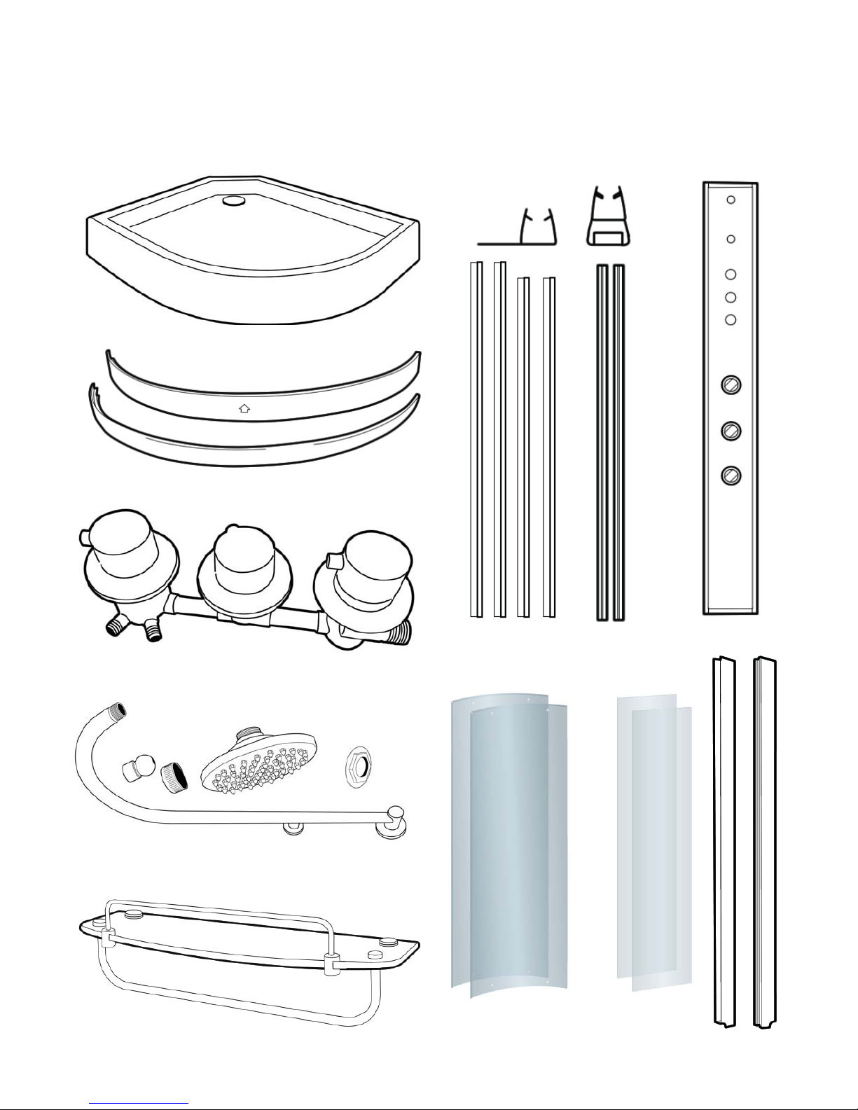
Below is a list of the parts you should have received for the installation of your shower. Please note that
several parts may be pre-tted in place, such as the monsoon shower head, etc. Please note, the design
and shape of parts may change occasionally but will always oer the same or greater functionality.
Hydro Shower Contents
1
2
3
5
6
8
9
4
7
3
1. Tray/Base with Waste assembly and exible waste pipe
pre-tted (shape and size vary according to model).
2. Two Curved polished Aluminium frame sections.
3. Thermostatic shower valve
4. Chrome monsoon arm, Monsoon head, swivel joint
and two nuts for fixing.
5. Glass shelf and ttings.
6. Two longer and two slightly shorter Flapped seals and a
pair of Magnetic door seals.
7. Tower with and Body Jets and shower valve
8. Two Curved clear glass doors. Two at clear glass side
pieces.
9. Frame Uprights. Two polished straight metal sections.
10. Back Glass Panels. Pair of glass with Polished Aluminium
frames.
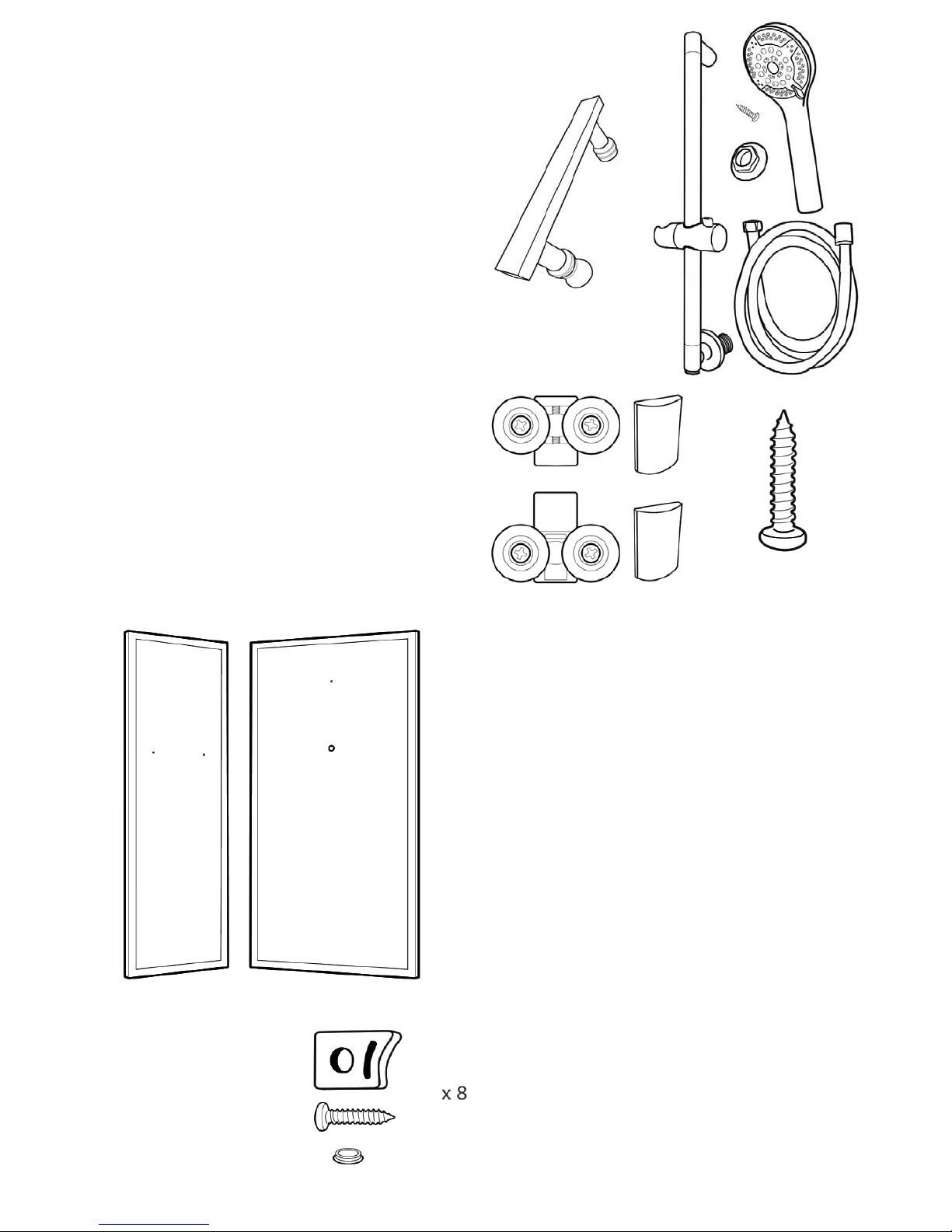
11.. 8 Door stops, short xingscr ews and cover caps.
12.. Two pairs of door handles.
13.. Hand Shower, riser bar, chrome hose and fixings.
14.. Eight Door wheel cams/runners. 4 x Quick Release, 4
x twin for upper rail fi tting and 8 cover caps.
15..Fitting Screws.
10
11
12
13
15
14

4
IMPORTANT NOTICE
Before you proceed with fi tting your Sensual Spa Shower please read and understand the following:
By commencing testing and installation of the unit you are agreeing to the Terms and Conditions
set out by us: copies of which are available by contacting us by by email or by telephone (details
on the cover of this manual).
You are required to ensure the purchased product dimensions allows for ease of passage to the
intended installation area.
Regarding weight tolerances of installation area, it is advisable to contact a builder or refer to
Building regulations to ensure the product placement area has su cient joist/ oor support.
1. It is important that you ensure that your purchase has been delivered undamaged. You are required to
check the contents and report any damage that you feel needs repairing or replacing within 48hrs of
receipt of goods. Items reported damaged after this time WILL be chargeable.
2. The product you have purchased is NOT designed for home DIY fitting. You are required under the
Terms and Conditions to get the unit fitted by a qualified specialist. The product requires connection to
electricity and this by law requiresa Part P qualified electrician. Failure to provide evidence of this will
void the relating product warranty
3. We are a supply only company. If you report to us any damage we will send replacements or solutions to
remedy the problem described. We endeavor to fully understand the problem rst by asking a series of
questions and then propose the solution. We may even ask for digital images to be sent via email to assist
the process. The warranty is parts only and does NOT include fitting/inconvenience or other related costs.
4. You are required to ensure that you correctly water test any bath tub before fitting and ensure that
your fitter fully tests the unit upon completion and attends to any leaks and faults before he leaves.
5. All hoses, such as to the valve assembly, shower outputs and air switches and waste are fittedfor
transport purposes and need to be properly sealed and tightened before use. During transportation
some connections can become dislodged and therefore break any watertight seal, you are required to
ensure that your tter specically tests for these possible occurrences and seal/xa ccordingly.
6. Do not book your tter until you have inspected the unit. We cannot be held responsible for delays
and costs incurred by tters having to return to t parts that need supplying.
7. We cannot be held liable for inconvenience caused due to lack of bathing facilities caused by any delay in
receiving your product or whilst awaiting parts.
8. Regarding our sales and technical support: We know our products and their requirements, but we are not
qualified plumbers or electricians and accept no liability for claims suggesting the same. You are advised
to check the suitability of the product with a professional body. It is the customer responsibility to ensure
the product is fit for purpose.
9.A 'Completion Certificate' is included at the end of the manual where you should record the details of
your installers - you will need this to record your warranty on our website.
ATTENTION
ALWAYS FIT EASY TO GET TO ISOLATION TAPS ON BOTH THE HOT AND COLD WATER
SUPPLY (NOT SUPPLIED). JUST LIKE A DISHWASHER OR WASHING MACHINE, THIS PRODUCT
MUST BE ISOLATED WHEN NOT IN USE.
REMEMBER:
These showers are designed to be free standing and movable from their location should you have the need to
replace anything. ALWAYS USE Flexible braided water inlet pipes (not supplied) at least a metre long (not
central heating plastic type!)
Always use a flexible waste pipe from your house supply to the shower .
NEVER FIX with rigid pipes, NEVER FIX the unit to the wall.

5
Before you begin
Tools needed to assemble this shower cabin:
Electric screwdriver with a selection of heads, regular screwdrivers, pipe grips, spanners, spirit level, sharp
knife and rubber mallet. Connection of the electrical supply and plumbing may require additional tools.
Do not fully tighten any screw fixings initially during build as this allows the frame to move a little
and aid location of all holes and screws; remember to fully tighten before completion and
subsequent use. There is a drill bit supplied with the kit, to allow either widening of holes or drilling
new holes which you feel cannot be located during construction.
Water requirements
This shower requires two water supplies (1 x hot and 1 x cold) tested to be between 1 and 3 bar, with
a fl ow rate over 7.5 litres per minute.
NOTE: We recommend water pressures over 2 bar to achieve optimum showering
results.
Gravity Fed systems
If you have a Gravity fed system, then fitting a Shower Pump will almost certainly be required. Fitting
a Shower pump rated over 1.5 bar is necessary as a minimum. Shower pumps MUST be properly
sited, installed and commissioned. Incorrectly installed shower pumps will cause adverse affects to
your showering and bathing resulting in pulsing or starting and stopping of the pump. If a pump is
installed, a separate Mains Cold supply must be fitted and directed to supply the Steam Generator
separately (bypassing the pump).
Isolating Valves
You MUST fit isolation valves to the shower unit on both hot and cold incoming feeds as it enables
you to turn off the water supply to the shower when not in use (for example going away on
holiday). Additionally isolating valves makes service checks easier than locating the house stop
cock.
Assembly requires two persons.
DUE TO THE NATURE OF THIS PRODUCT WE HIGHLY ADVISE THE PURCHASE AND FITTING OF A
WATER SOFTENER
(PLEASE NOTE LIMESCALE BUILD UP MAY CAUSE DAMAGE TO YOUR SHOWER AND WILL NOT BE
COVERED UNDER WARRANTY)
6
Assembly
Do not t the shower into locations where you do
not have at least 40cm access all around the cabin
both for installation and for future service access.
We advise you do not fit sinks, toilets etc that
restrict access behind the shower.
You must ensure you can slide the cabin away from
the wall/corner for service access.
Smooth and level walls and oor are required for
ideal installation conditions. Avoid carpet or vinyl
oors.
Please ensure you have correctly water tested the
tub before you continue.
NOTE: Instructions shown based on quadrant
model, The assembly and operation is identical
for o set models except for the rear panels
being di erent sizes.
Please inspect all parts carefully before
assembly.
BY COMMENCING ASSEMBLY OF THIS SHOWER
YOU ACCEPT THAT THE PARTS HAVE ALL BEEN
CHECKED AND ARE UNDAMAGED.
This product is fitted with
toughened safety glass. The
glass is stronger than regular
glass and if it breaks it will form
small pieces of cubed glass, not
dangerous shards of glass. These small
pieces are still sharp, so care must be
taken to handle broken glass with care.
If the glass is put under stress or is chipped
it will break.
DO NOT ALLOW THE GLASS TO IMPACT
HARD SURFACES OR OBJECTS AS
THIS MAY CHIP/WEAKEN THE GLASS.
WEAKENED GLASS THAT IS CHIPPED OR
UNDER TENSION MAY SHATTER AT ANY
TIME, NOT ALWAYS IMMEDIATELY.
REMOVE THE WHITE PLASTIC COVER ON
THE BACK OF THE TOWER PANEL IF YOU
WISH FOR BETTER FITTING TO THE WALL
Fitted to the rear
of the tower panel
is a white plastic
protective cover.
This part is tted to
protect the valve
and pipes during
transport.
You may choose to
REMOVE and
DISPOSE of this part
as it is not needed.
7
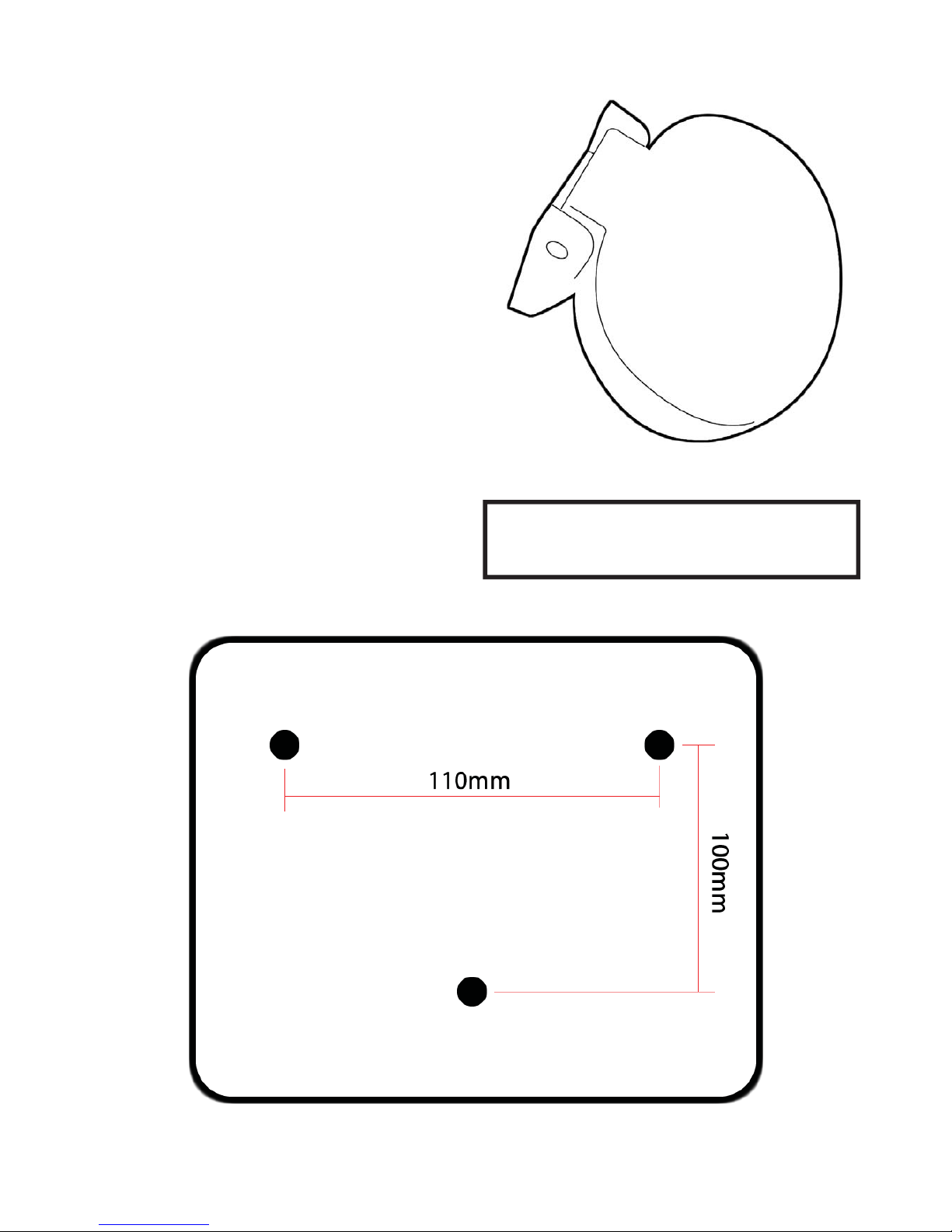
FITTING SEAT (OPTIONAL)
If your product came with a seat you may choose
to install this item.
Before commencing full assembly of the product
you will need to prepare and t the seat.
You need to drill three holes for the xing bolts
into the tower at your preferred height.
Drill the holes in the central tower to the
measurements shown in the diagram below.
Remove the three xing nuts from the threaded
ends on the rear of the seat xing plate.
Pass the threads of the seat through the holes from
the front of the tower panel.
At the rear, pass the threads though the white
support piece (white plastic) and then fasten the
bolts to hold.
Ensure the bolts are FULLY tight.
The seat has a MAX allowance
for use of 100kg

8
LEVELING AND FITTING THE TRAY
Remove the protective lm covering the base.
Connect the soil pipe, trap and any couplings to the exible waste under the tub. You may choose to
t either a HEPV0 trap with the appropriate couplings or choose to t a McAlpine ST28M coupling to a
McAlpine 28-NRV trap.
Position the tub base in what will be its nal location and adjust the feet until the base is level. You can
raise/lower the feet under the tub and with a spirit level laid across the tub, ensure the tub is level.
Now ll the base with some water and check that the water ows adequately to the plug and exits
satisfactorily. If the water does not ow to the plug fully, then you will need to increase the fall on the
tray by adjusting the legs. If the water does not exit the waste section fast enough, then ensure there is
suitable fall in the waste pipe and/or no blockage or kinks in the pipe work.
Check and attend to any leaks.
Now slide the tub away from the wall to allow access all around the shower as you assemble.
This product is freestanding so you do not need to x the feet to the oor.
9
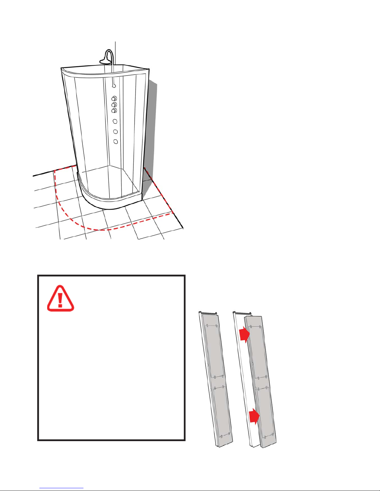
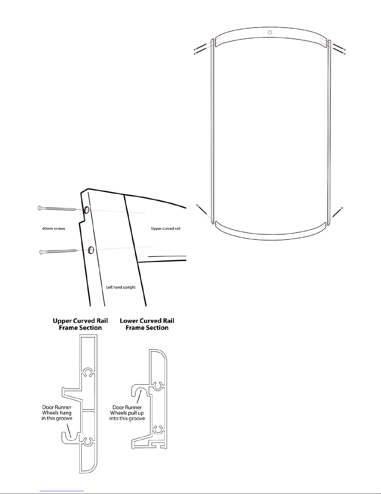
FRONT FRAME
Locate the two silver coloured upright frame
sections and the two curved frame rail sections.
You will need the 8 x LONG screws to join these
sections together.
The upper rail is deeper height than the lower rail.
Align the upright with two holes in, to the upper
curved rail. The screws pass through the holes in
the side of the upright and fasten into the curved
rail as shown in the digram below.
A power driver is advised for this process.
DO NOT FULLY TIGHTEN THE SCREWS -
ALLOW SOME MOVEMENT IN THE FRAME FOR
INSTALLING THE FIXED GLASS
Repeat the process on the other upright.
Finally, join the lower curved rail to the other ends
of the uprights using a single long screw.
You now have completed the front frame assembly.

10
INSTALLING THE FIXED SIDE GLASS PANELS
Remove the SEAL TRIM that is located in the inside
edge of the lower curved rail. It is held in position
by two screws. Remove this trim to help you t the
xed side glass panels. You will need to re-attach it
after the glass is tted.
Locate the two xed glass panels. These are
dierent from the doors as they do NOT have any
holes pre-drilled.
Locate the two U shaped rubber seals.
Take one of the U shaped seals and t over one
long edge of the xed glass panels. Trim any excess
leaving it running the full length.
Now position this glass panel up to the frame
pushing the long edge of the glass into the
upright of the frame until FULLYbedded into the
frame upright.
This MUST be done from the inside of the frame.
The glass will sit within a lip on the inner surface of
the curved rail both top and bottom.
DO NOT HIT GLASS WITH HARD
OBJECTS TO PUSH INTO THE FRAME.
Now both glass panels are fully inserted into the
uprights you can tighten up the four corners of the
silver framework which will not hold the glass in
position.
Repeat this process on the other glass panel.

11
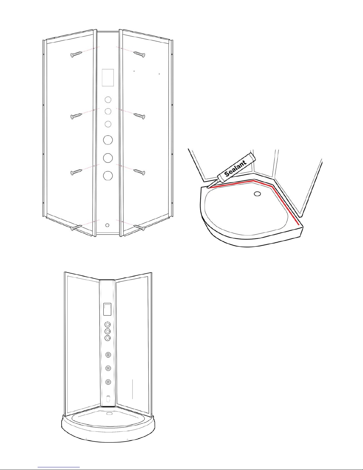
REAR PANEL ASSEMBLY
Locate the two rear, framed glass panels. Each
is marked (LEFT or RIGHT). The inside edge to
go to the center control panel will be flat. The
outside end to connect to the frame work will
have a 'T' end
Facing the shower from the front, the panels t
according to their label.
Now position the Central Tower Panel between the
rear panels.
Align the holes on the rear panels to those in the
tower and x in place with the screws provided.
Using 8 of the shorter screws, x through the rear
glass panel xing holes into the central tower. DO
this on both long sides of the tower.
NOTE: A bead of sealant can be run
between the joining faces of the back
panels and Center Tower to provide an
extra level of water protection.
You should consider doing this on all
panels with meeting faces then simply
wipe off any excess so non will be 'on
show'
Now both glass panels are fully inserted into the
uprights you can tighten up the four corners of the
silver framework which will not hold the glass in
position.
Next you need to t the Retaining Clips to hold the
glass rmly. Position a clip tight up to the glass on
the inside of the upper and lower rails, mark the
position and drill a small hole then x a screw to
hold the clip in place. Repeat top and bottom on
both xed glass panels.
CAUTION WHEN DRILLING - ONLY DRILL
THROUGH THE INNER SINGLE LAYER OF FRAME
Re-x the SEAL TRIM back on the inside of the
lower curved frame.
GLASS RETAINING CLIPS
12
TIP: Only t each screw loosely at rst to allow
enough movement to locate every screw hole.
Once all screws are located in place, then tighten
each screw up fully.
Carefully lift the three joined sections onto the tray
into position.
A bead of sealant along the tray where the panels
will sit will provide a watertight barrier.
Remember to remove any excess sealant once the
panels have been seated into position.
DO NOT SCREW THE PANELS TO THE TRAY JUST
YET.
(Above) 8 x Short Screws used to join rear glass
panels to tower panel. (viewed from rear)
13
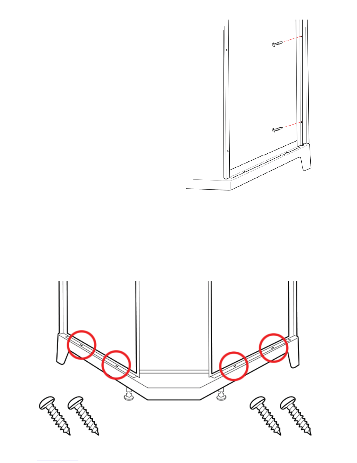
FIXING THE BACK PANELS TO THE TRAY
The rear glass panels can now be xed to the tray.
At the rear of the shower the lip of the frame has xing holes to enable the screws provided to be used
to fasten the rear glass panels to the tray. There are 4 xing points.
Fixing is done with the short screws provided.
FITTING THE FRONT FRAME
Place the completed front frame section onto the
front of the shower tray and align the uprights
with the rear glass panels so that the xing holes
line up.
From behind the side panel front edge locate a
screw hole into the front frame screw through the
lip of the white framework of the rear glass panels
into the frame to secure in place. (8 x short screws)
The help ease this process, you may need to use
the supplied drill bit in the holes to ensure they are
wide enough and clear.
NOTE: A bead of sealant can be run
between thebetween the back panels
and Front Frame work to provide an
extra level of water protection.
Simply wipe off any excess so non will
be 'on show'
14
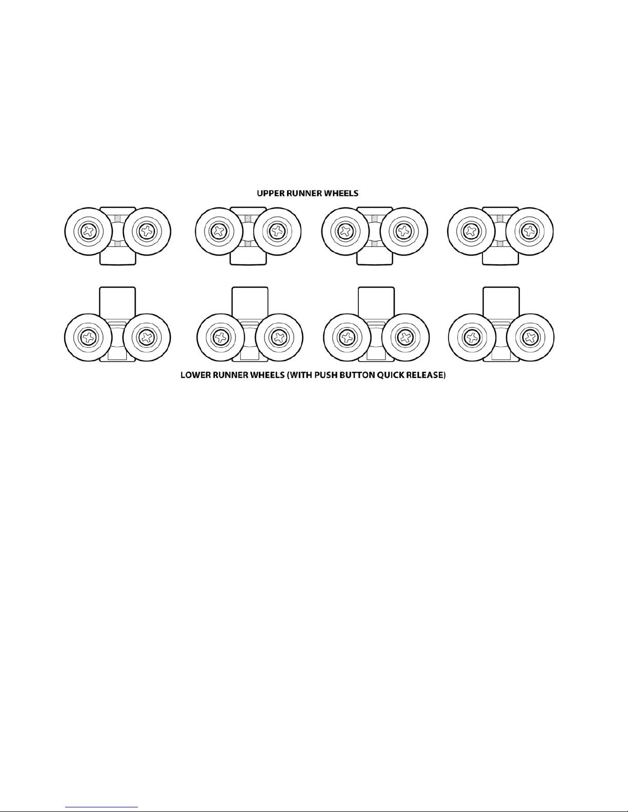
FITTING THE SHOWER DOOR WHEEL RUNNERS
Locate the pack of 8 twin wheel shower door runners (cams).
There are two dierent types provided.
Continued...
Before You Fit The Doors You May Wish To See The "SEALING THE
SHOWER" Section Of These Instructions And Apply Sealant Around
The Base Of The Tray Prior To Fitting The Doors
15
(image based on
top cam tting)
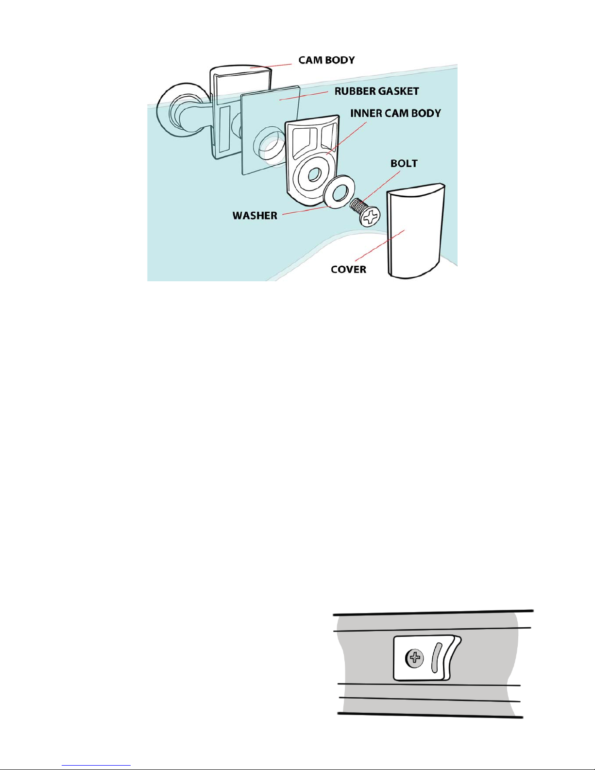
To fit each of the cams, first select the appropriate cam for the position on the door:
4 x Push button/Quick release for the lower position on the doors.
4 x Standard non push button for the upper position on doors.
Position the Cam Body on the outside facing side of the door (curve pointing outwards). Place the clear
rubber gasket between the cam body and the glass. The gasket will t into the hole on the glass.
On the inside of the door, position the grey plastic inner cam body, then washer and bolt.
Now tighten the parts together with the bolt until rmly held in place.
DO NOT OVER TIGHTEN AS YOU MAY BREAK THE GLASS
With the cam xed in position, slide on the Chrome nished cover.
Repeat this process of all of the cam wheels.
TO HANG THE DOORS
From inside the shower position the upper wheels into the running tracks on the inside curve of the
upper curved rail and then let the door hand down.
From outside the shower, move the door to what would be a closed position and press the quick release
buttons on the top of the lower cams and move the wheels
to t into the lower runner tracks.
Repeat for the other door.
DOOR STOPS
On the inside curve of the upper and lower rail are some
holes pre-drilled. Fix each of the 8 door stops at these
locations with the provided screws. The stops also have a
grey cap to cover the screw in the stopper of each —these
simply push into place.
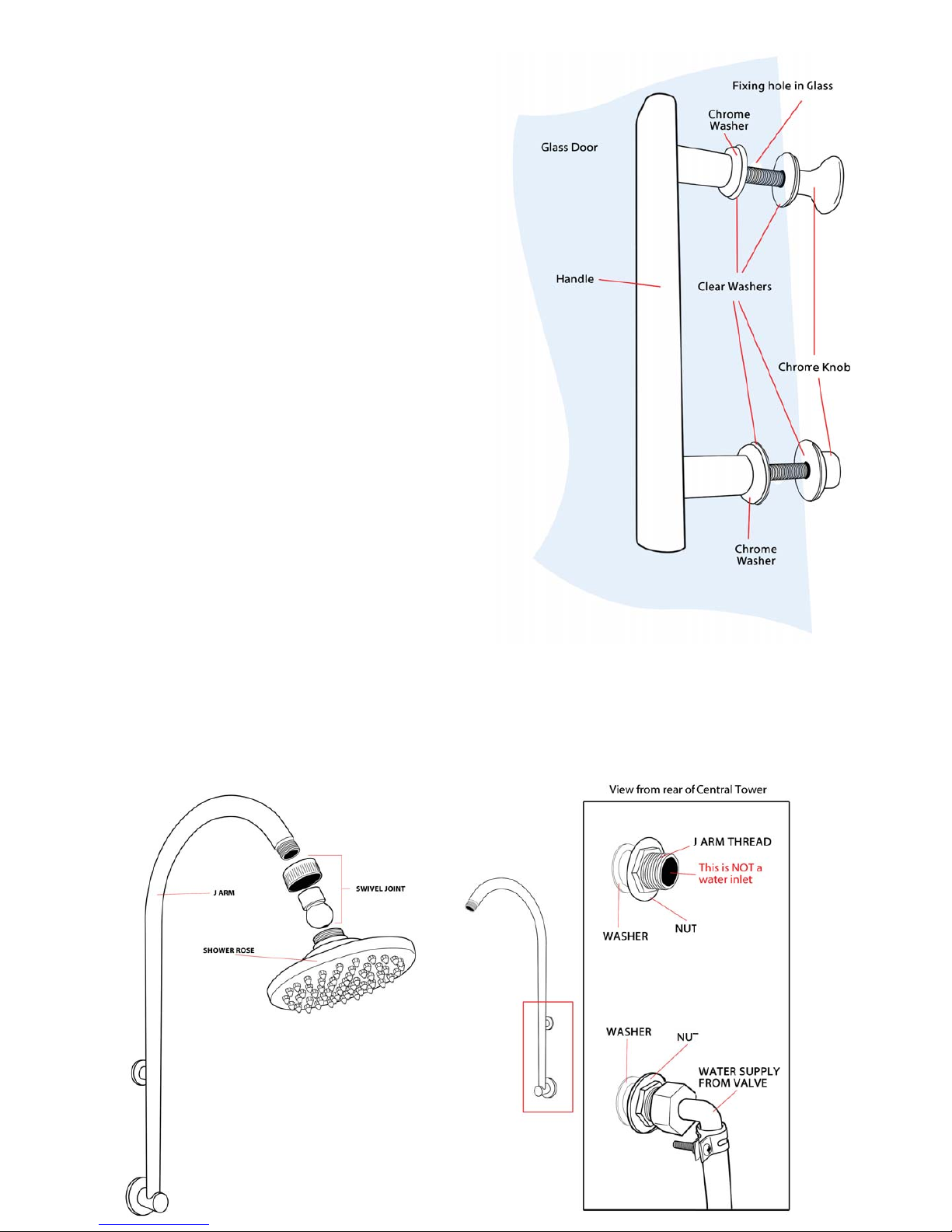
FITTING THE DOOR HANDLES
Each of the two shower doors requires a pair of
chrome nished door handles to be tted.
Each handle is comprised of several parts. Position
the main handle part on the outside of a door
ensuring the Chrome Washer and a Clear Washer
are positioned also on the outside face over the
thread. Push the threaded ends through the glass.
Next place another clear washer on the threads
and then screw on the two dierent Chrome Knobs
to the inside of the glass door.
Tighten until secure. DO NOT OVER TIGHTEN.
TEST FOR LEAKS
Make sure the connection is tested and is
watertight. You may wish to use some PTFE
tape or other suitable products to provide the
best water tight seal on this joint.
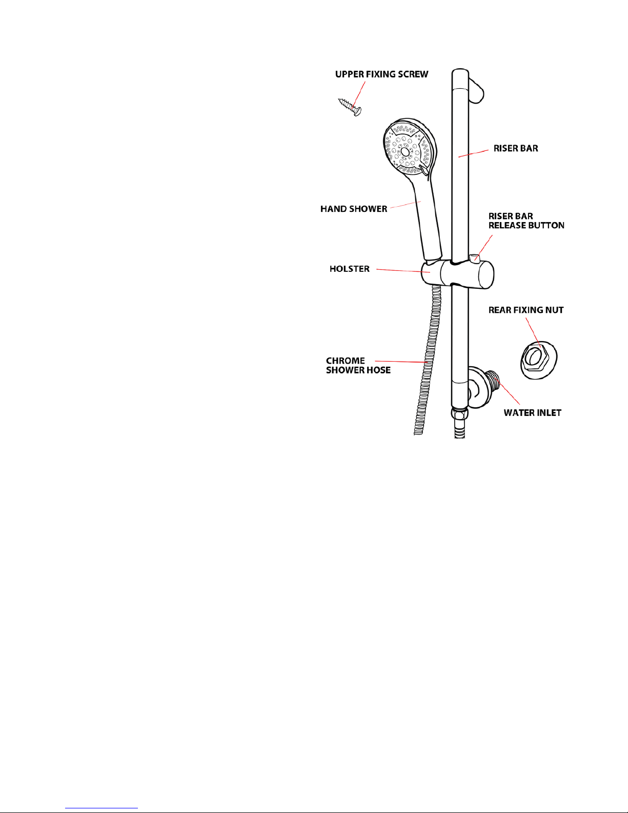
OVERHEAD SHOWER
The overhead shower is comprised of three parts.
A chrome ‘J’ shaped arm, a Chrome finished
overhead shower rose and a swivel joint. The joint
may be pre-fitted to the shower rose.
The J Arm has two fixing points on the straight
section that are threaded. Remove the fixing nuts.
Position the threaded sections through the holes in
the upper part of the central glass tower panel on
the inside of the shower.
With the nuts that you removed, fasten at the rear
on to the protruding threaded ends to fix the arm in
place.
Now connect the rose and swivel joint to the arm.
At the rear of the shower, connect the hose that is
coming from the top of the valve to the lower
(water in part) of the J Arm.
17
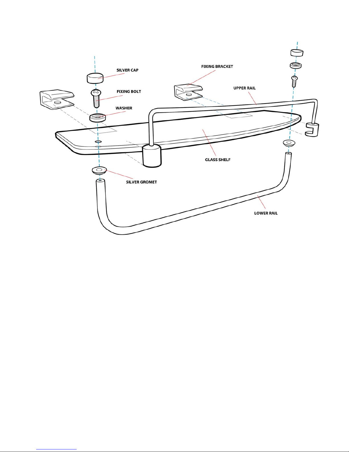
HAND SHOWER AND RISER
You are now ready to assemble and connect the
hand shower.
The hand shower comprises of:
Multi function hand shower
Chrome nished riser bar
Hand shower holster
Chrome water hose
Rear retaining nut
Fitting screw
The lower part of the riser bar has a threaded water
connection. Position this part through the larger
hole on the rear glass panel.
Fit the rear xing nut from the rear of the shower
to hold in place. Secure the upper part of the riser
bar with the screw provided. Tighten both until
secure.
Connect the silver hand shower hose to the lower
part of the riser bar and the other end to the hand
shower head.
At the rear of the shower, locate the grey water
supply hose coming from the shower valve and
connect to the water inlet of the riser bar. Test this
water connection to ensure it is water tight. Using
some PTFE tape or other product may help to
achieve the best watertight connection.
18
GLASS SHELF
Assemble the shelf fully before fitting into the shower.
Position the lower chrome rail over the holes in the glass on the underside of the shelf with the silver
grommets positioned between the two.
On the upper side of the glass, pass the bolt through a washer and through the hole in the glass and
fasten into the end of the lower rail.
Repeat the previous step on the other end of the lower rail so that the rail is securely fixed in place.
Take the two silver caps and fit them over the ends of the washer and bolt to provide a clean finish.
The upper rail pushed over the glass from the front. Using a at head screwdriver, tighten up the xing
point of the front rail, which is located on the underside.
Position the two xing brackets onto the inside of the rear panel of the shower in the holes provided. Fix
the brackets at the rear of the shower with the supplied bolts and washers.
Place the glass of the shelf centrally into the slots of the brackets and then tighten the xing points
on the underside of the brackets to hold the shelf in place. DO NOT OVER TIGHTEN THE BRACKET
CONNECTIONS AS THIS MAY BREAK THE GLASS.
Table of contents
Popular Hot Tub manuals by other brands

Aquaparx
Aquaparx SPA550 user manual

Marco Mammoliti
Marco Mammoliti Jeolys 82604487 INSTALLATION, USE AND MAINTENANCE INSTRUCTION MANUAL

Aquatic
Aquatic Point Arena AI6060DC Specification sheet

American Spas
American Spas AM-730B-M owner's manual

Jacuzzi
Jacuzzi MAJORA 6 Specification sheet

SpaDealers
SpaDealers CityTub instructions


Conair
Conair CTX 0 7C operating instructions

Fisherspas
Fisherspas Fisher Two owner's manual

HotSpring
HotSpring Portable Spaa owner's manual

Jacuzzi
Jacuzzi Projecta JP 7 Electrical diagrams

American Standard
American Standard Cadet 2776 W Series installation instructions

Sanotechnik
Sanotechnik SanoSpa SPA08 Programming instructions