Sentrol 4300 Series User manual
1
CSFM
4300 Series
Wireless Smoke Detector
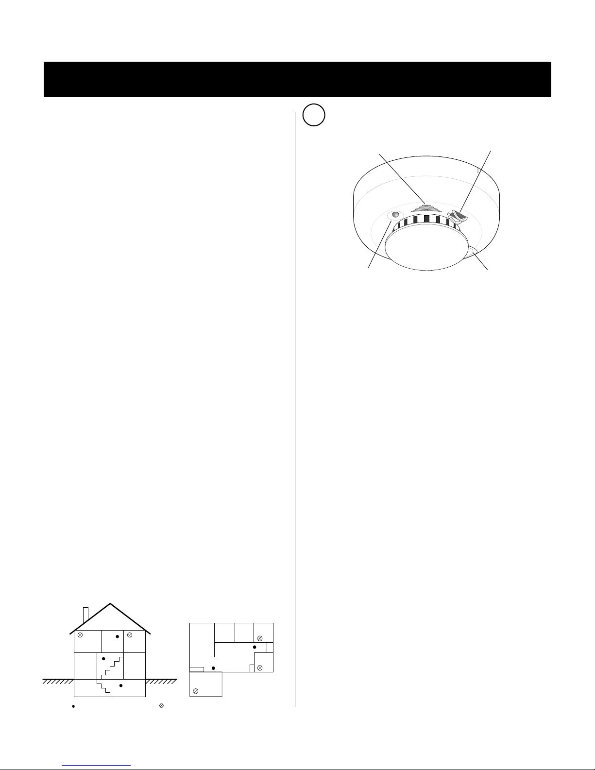
LED Test/Silencebutton
Soundervent Optionaltemperaturesensor
Figure 1 - Detector Features
DESCRIPTION
The Sentrol 4300 Series smoke detector requires a
Sentrol 4000 RF gateway receiver with Rev J or higher
software and a compatible control panel sold sepa-
rately. To install the detector, you will need the
programming guide for the control panel.
Depending on the model, the detector provides the
following features:
CleanMe™self-diagnostics monitors its own sensitiv-
ity and operational status. If the detector drifts out of
the UL listed sensitivity range or fails internal diagnos-
tics, it extinguishes its LED and sends a trouble signal
to the control panel.
Detector/base lock discourages unauthorized removal
of the detector by requiring a screwdriver to remove
the detector from the base.
Optional base tamper sends a trouble signal to the
control panel when the detector is removed from its
mounting base.
Optional mercury-tilt tamper sends a trouble signal
to the control panel when the detector is not upside
down and/or horizontal. Used for installations on
removeable ceiling panels
Optional integrated fixed 135°F temperature and
rate of rise heat detector trips an alarm based on
temperature detected.
Optional low temperature supervision sends a low
temperature signal when the ambient temperature
around the detector reaches approximately 43°F (6°C).
A separate transmitter signal (secondary address) is
assigned to a Critical Condition Monitoring(CCM) zone.
TRANSMITTED SIGNAL OUTPUTS
Depending on the model, the detector transmits the
following signals to the control panel:
• Alarm
• Alarm restore
• Tamper
• Low battery
SELECTING A LOCATION
Selecting a suitable location is critical to the operation
of smoke detectors. This equipment should be installed
in accordance with the National Fire Protection
Association’s (NFPA) Standard 72. See Figure 2.
A-8-1.2.1.C Are More Smoke Detectors Desirable?
The required number of smoke detectors might not
provide reliable early warning protection for those areas
separated by a door from the areas protected by the
required smoke detectors. For this reason, it is recom-
mended that the householder consider the use of
additional smoke detectors for those areas for in-
creased protection. The additional areas include the
basement, bedrooms, dining room, furnace room, utility
room, and hallways not protected by the required
smoke alarms. The installation of smoke detectors in
kitchens, attics (finished or unfinished), or garages is
not normally recommended, as these locations occa-
sionally e perience conditions that can result in im-
proper operation.
Important: Regulations pertaining to smoke detector
installations vary from state to state. For more infor-
mation, contact your local fire department or local
authority having jurisdiction.
UL
LISTED
U
N
D
E
R
W
R
I
T
E
R
S
L
A
B
O
R
A
T
O
R
I
E
S
O
F
C
A
N
A
D
A
L
I
S
T
E
D
B
Y
Figure 2 - Detector Placement
Wireless
sentrol
4300 Series
Wireless Smoke Detector
UL
LISTED
•CleanMe™
•Maintenance alert
•Supervisory
•Low temperature supervison
TV Room
Dining
Room Kitchen Bedroom
Bedroom
Bedroom
Living Room
= Required smoke detectors
Dining
Room
Basement
Bedroom Bedroom
Living
Room
= Additional smoke detectors required for new construction
2
In addition to NFPA 72, use the following location guide-
lines to optimize performance and reduce the chance of
false alarms from the detector:
•Locate ceiling-mounted smoke detectors in the center
of a room or hallway at least 4 inches from any walls
or partitions.
•Locate wall-mounted smoke detectors so the top of
the detector is 6 to 12 inches below the ceiling.
•Locate in a suitable environment as follows:
- Temperature between 40°F (4.4°C) and 100°F (37.8°C)
- Humidity between 0 and 95% non-condensing
•Locate away from air conditioners, heating registers
and any other ventilation source that may interfere
with smoke entering the detector.
•Mount smoke detectors on a firm permanent surface.
If the detector has a tilt tamper, it can be mounted on
removable ceiling panels.
•Locate away from large metallic objects.
INSTALLING THE DETECTOR
1. If you are using the detector/base lock, remove the
two knockouts on the mounting base. See Figure 3.
2. Slide the battery compartment cover away from the
detector to unsnap it and lift it off. See Figure 4.
3. Observing proper polarity, insert the two lithium
batteries provided into the detector battery compart-
ment and replace the battery compartment cover.
4. Record the seven digit ID address from the label on
the backside of the detector. This address must be
programmed into the RF gateway receiver. See the
control panel programming guide.
For an L model detector, program the “Fire Address
plus 1”secondary address into the panel in a separate
non-fire CCM non-supervised or 24hr non-supervised
auxiliary zone.
5. Program the RF gateway receiver and the control
panel. See the control panel programming guide.
6. Remove the red plastic dust cover from the detector.
The detector is shipped with a dust cover for protec-
tion on construction sites with dusty environments.
7. Disconnect the alarm notification appliances, service
release devices, and extinguishing systems and test
the communication between the control panel and
each smoke detector before permanently mounting the
detectors as follows:
-Press the Test/Silence button on the detector for
2 seconds. The detector sends a test signal to the
control panel.
-At the control panel, verify the test signal
was received and the RF signal strength is ad-
equate. If no signal is received or the RF signal is
low, relocate the detector and retest.
8. Using the two screws and anchors provided, mount
the base.
9. Attach the detector to the mounting base as follows:
-Line up the raised tab on the lip of the detector with the
slot on the lip of the mounting base. See Figure 4.
-Insert the detector into the base and turn clockwise
approximately 15 degrees. It should snap firmly into
place.
Important: The detector cannot be attached to the
mounting base if no batteries are installed.
10.Test the communication between the control panel
and each smoke detector as follows:
-One at a time, press the Test/Silence button on the
detector for 2 seconds. The detector sends a test
signal to the control panel.
-At the control panel, verify the test signal was
received.
11. Test each detector (see
Smoke Testing the
Detector)
and reconnect all alarm notification
appliances, service release devices, and extinguish-
ing systems.
Important: The control panel alarm and all auxiliary
functions should be verified for a complete test of the
system.
Knockout
Knockout
Figure 3 - Base Lock Knockouts
Figure 4 - Detector-to-Base Alignment
Tab
Slot
Battery
compartment
3
SMOKE TESTING THE DETECTOR
Smoke detectors should be tested in place annually
using smoke or canned aerosol simulated smoke.
Follow the instructions on the canned smoke or use the
following steps to test the detector with smoke:
1. Hold a smoldering punk or cotton wick close to the
smoke entry openings.
2. Gently direct the smoke into the detector for 20
seconds or until an alarm is indicated.
BE SURE TO PROPERLY EXTINGUISH THE SMOKE
SOURCE AFTER TESTING! The detector LED should
remain on while the built-in transmitter sends an alarm
signal to the control panel. The detector will sound a
temporal rhythm until the Test/Silence button is pressed.
The detector automatically resets when smoke is no
longer present.
UNDERSTANDING THE TEST/SILENCE BUTTON
Depending on the model, the Test/Silence button on
4300 Series performs three functions as follows:
Testing = Press the Test/Silence button for 2 seconds.
The detector performs a sounder test (4310 models
only) and a sensitivity test and then sends a test signal
to the control panel.
Silence alarm = Press to silence the sounder during
an alarm. After a few minutes, the sounder and alarm
resume if smoke is still present.
Silence trouble chirp = Press to silence a trouble
chirp. The trouble chirp resumes after 24 hours if the
trouble condition is not corrected.
UNDERSTANDING THE LED
The LED on the 4300 Series indicates the status of the
detector as follows:
FLASHING = Flashes every 9 seconds to indicate normal
operation.
ON = Detects smoke, sending an alarm.
OFF = Trouble or maintenance is required. Check the
control panel to determine what action to take.
ATTACHING AND REMOVING THE DETECTOR
To remove the detector from the mounting base,
grasp the detector and turn it counterclockwise approxi-
mately 15 degrees. The detector should snap off of the
mounting base.
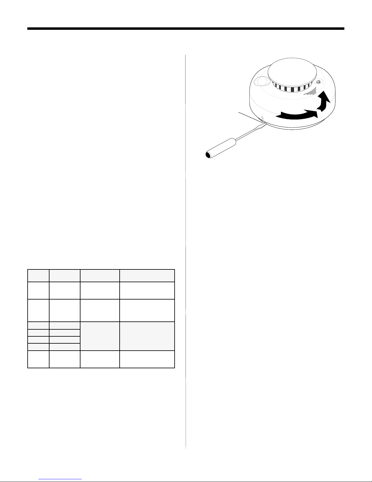
To remove the detector from the mounting base
when the detector/base lock is used, insert a small
screwdriver into the locking tab slot on the side of the
base and press in while simultaneously turning the
detector counterclockwise 15 degrees. See Figure 5.
TESTING THE DETECTOR SENSITIVITY
The 4300 Series provides a sensitivity level test mode that
allows you to check the detector sensitivity using the Test/
Silence button and the LED indicator on the detector as
follows:
1. Press the Test/Silence button on the detector for 2
seconds. The detector performs a test, and the LED
flashes one to nine times.
2. Count the number of times the LED flashes and use the
following table to determine the status of the detector
sensitivity and what action to take, if any.
Figure 5 - Detector/Base Lock
Detector/baselock
After the flashes, if the sensitivity is within limits
and all other tests pass, the detector goes into
alarm and resets after 5 seconds.
If the sensitivity is not within limits, or an unservice-
able hardware fault is detected, the LED extinguishes
until the detector is serviced and the built-in transmitter
sends a CleanMe™or maintenance alert signal to the
control panel.
sehsalF noitarucsbO )xorppA( noitacidnI noitcA
1A/NelbaecivresnU tluaferawdrah .detceted
nurerdnatinuteseR rorreehtfI.tsetytivitisnes .tinuehtecalper,stsisrep
3-2A/NtonsirotceteD .hguoneevitisnes tinuteseR.tinuehtnaelC .tsetytivitisnesnurerdna ,stsisreprorreehtfI .tinuehtecalper
4 tf/%1.3 nihtiwsirotceteD ytivitisneslamron .egnar
A/N
5 tf/%6.2
6 tf/%1.2
7 tf/%6.1
9-8A/NootsirotceteD .evitisnes ekomsehttahtyfireV deppanssirebmahc .tinunaelC.ylerucesnwod

4
Figure 6 - Removing Detector Cap
Attach the smoke detector to its mounting base as
follows:
- Line up the raised tab on the lip of the smoke detector
with slot on the lip of the mounting base. See
Figure 4.
- Insert the smoke detector into the base and turn
clockwise approximately 15 degrees. It should snap
firmly into place.
WHEN TO REPLACE THE BATTERIES
When the batteries are low, the detector sends a low
battery signal to the control panel, waits several days
and then chirps every 30 seconds until the batteries are
replaced. The sounder can be silenced for 24 hours by
pushing the Test/Silence button. See
Specifications
for
battery type list.
REPLACING THE BATTERIES
Use only 3V lithium batteries listed in
Specifications
in
the detector.
1. Remove the detector from the mounting base. See
Attaching and Removing the Detector.
2. Slide the battery compartment cover away from the
detector to unsnap it and lift it off. See Figure 4.
3. Remove the batteries and dispose of properly.
4. Observing correct polarity, insert two new 3V lithium
batteries into the battery compartment and replace
the cover.
5. Reattach the detector to the mounting base. See
Attaching and Removing the Detector.
6. Test the system.
CLEANING THE DETECTOR
Clean the detector cover with a dry or damp (water)
cloth as needed to keep it free from dust and dirt.
When necessary, clean the detector interior and
replace the smoke chamber as follows:
1. Disconnect the alarm notification appliances, service
release devices and extinguishing systems.
2. Remove the detector from its mounting base. See
Attaching and Removing the Detector.
3 Remove the batteries
.
See
Replacing the Batteries.
4. Slide a flat-blade screwdriver in the slot on the
detector cap and gently push the handle down to pry
the cap up and off. See Figure 6.
5. Press in on the sides of the smoke chamber and pull
it up and away from the detector and discard. See
Figure 7.
6. Blow out or use a soft-bristled brush to remove dust
and dirt from the smoke chamber base.
7. Line the new smoke chamber up with the smoke
chamber base and snap down into place.
8. Replace the detector cap as follows:
-Line the cap up with the smoke detector.
-Insert the cap into the smoke detector and turn
clockwise approximately 15 degrees. It should
snap firmly into place.
9. Observing the proper polarity, put the batteries back
in the detector and replace the battery compartment
cover.
10.Reattach the detector to its mounting base. See
Attaching and Removing the Detector.
11.Test the detector sensitivity (See
Testing the Detector
Sensitivity)
and reconnect all alarm notification
appliances, service release devices and extinguish-
ing systems.
Important: The control panel alarm and all auxiliary
functions should be verified for a complete test of the
system.
Smoke
chamber
SQUEEZEHERE
Detector
Opticalbase
Smoke
Indentation
Figure 7 - Detector Parts

5
FIRE PREVENTION AND ESCAPE
The purpose of an early warning smoke detector is to
detect the presence of fire in its early stages and
sound an alarm giving the occupants time to exit the
premises safely.
Avoid Fire Hazards
No detection device can protect life in all situations.
Therefore, safeguards should be taken to avoid
potentially dangerous situations as follows:
•Do not smoke in bed
•Do not leave children home alone
•Never clean with flammable liquids such as gaso-
line.
•Properly store materials. Use general good house-
keeping techniques to keep your home neat and
tidy. A cluttered basement, attic, or other storage
area is an open invitation to fire.
•Use combustible materials and electrical appliances
carefully and only for their intended uses. Do not
overload electrical outlets
•Do not store explosive and/or fast burning materials
in your home.
•Even after proper precautions have been taken, fires
can start. Be prepared.
In Case of Fire
In the event of a fire, you should do the following:
•Leave immediately. Don’t stop to pack or search for
valuables.
•In heavy smoke, hold your breath and stay low,
crawl if necessary. The clearest air is usually at the
floor.
•If you have to go through a closed door, carefully
feel the door and door knob to see if undue heat is
present. If they seem cool, brace your foot against
the bottom of the door with your hip against the door
and one hand against the top edge. Open it slightly.
If a rush of hot air is felt, slam the door quickly and
latch it. Unvented fire tends to build up considerable
pressure. Be sure all members of the household
realizes and understands this danger.
•Use your neighbor’s phone or a street fire alarm box
to call the fire department. The job of extinguishing
the fire should be left to the professionals.
Be Prepared
Practice the following steps to prepare you and your
family in the event of a fire:
•Perform fire drills regularly. Use them to assure
recognition of an alarm signal.
•Draw a floor plan and show two exits from each
room. It is important that children be instructed
carefully, because they tend to hide in times of
crisis.
•Establish one meeting place outside the home.
Insist that everyone meet there during an alarm.
This will eliminate the tragedy of someone reenter-
ing the house for a missing member who is actually
safe.
•If you have children and/or physically challenged
people residing in your household, use window
decals to help emergency personnel identify the
sleeping quarters of these individuals.
LIMITED WARRANTY
Sentrol is a brand name of SLC Technologies,Inc. The
manufacturer warrants this smoke detector (except
batteries) to be free from defects in material and work-
manship under conditions of normal use for a term of 3
years from the date of manufacture.
During the warranty period, if a Sentrol product or any of
its components becomes defective, it will be repaired or
replaced without charge.
Out-of-warranty units will be repaired at the discretion of
the manufacturer or, if not, a card will be forwarded to the
customer suggesting a replacement unit and the cost of
that unit.
This warranty does not apply to units which have been
subject to abuse, misuse, negligence or accident, or to
which any modifications, alterations or repairs have been
made or attempted.
This warranty is extended only to the original purchaser of
the smoke detector and may be enforced only by such
person. During the warranty period, if the detector or any
MAINTAINING THE DETECTOR
The 4300 Series smoke detectors are designed for
easy field service and maintenance. When installed
and used properly, they require minimal maintenance.
The smoke detector should be tested weekly. See
Testing the Detector Sensitivity
and
Smoke Testing the
Detector
.
When the detector requires maintenance, it extin-
guishes its LED and sends a signal to the control panel
as described in the following table.
langiS deriuqerecnanetniaM
eMnaelCdnaegnarfotuosiytivitisnesrotcetedekomS eeS.gninaelcsdeen
rotceteDehtgninaelC
.
trelaecnanetniaMamrofreP.tsetflespurewopdeliafrotceteD eeS.tsetytivitisnes
rotceteDehtgnitseT
ytivitisneS
ehtecalper,stsisrepmelborpehtfI.
.rotceted
yrettabwoLehtecalpeR.wolerarotcetedehtniseirettaB .seirettab
Detach and leave with the end user
✄
✄

6
warranted components thereof becomes defective, it will
be replaced or repaired without charge at the
manufacturer’s discretion if returned in accordance with
the following instructions:
Obtain a Return Authorization Number by calling 1-800-
648-7422 or 503-692-4052, then carefully pack it in a well
padded and insulated carton and return, postal charges
prepaid to:
Customer Service
Sentrol
12345 SW Leveton Drive
Tualatin, OR 97062-9938
A note should be included advising the nature of the
malfunction. Care must be exercised in the proper
packing of detectors returned under this warranty as
Sentrol will not be responsible for warranty repairs to
equipment damaged because of improper packing.
THE ABOVE WARRANTY IS IN LIEU OF ALL OTHER
EXPRESS WARRANTIES, AND IMPLIED WARRAN-
TIES OF MERCHANTABILITY AND FITNESS FOR A
PARTICULAR PURPOSE ARE LIMITED IN DURATION
FOR A PERIOD OF THREE YEARS FROM THE DATE
OF MANUFACTURE. UNDER NO CIRCUMSTANCES
SHALL MANUFACTURER BE LIABLE TO THE PUR-
CHASER OR ANY OTHER PERSON FOR INCIDENTAL
OR CONSEQUENTIAL DAMAGES OF ANY NATURE,
INCLUDING WITHOUT LIMITATION DAMAGES FOR
PERSONAL INJURY OR DAMAGES TO PROPERTY,
AND HOWEVER OCCASIONED, WHETHER ALLEGED
AS RESULTING FROM BREACH OF WARRANTY BY
MANUFACTURER, THE NEGLIGENCE OF MANUFAC-
TURER OR OTHERWISE. MANUFACTURER’S LIABIL-
ITY WILL IN NO EVENT EXCEED THE PURCHASE
PRICE OF THE PRODUCT. SOME STATES DO NOT
ALLOW LIMITATIONS ON HOW LONG AN IMPLIED
WARRANTY LASTS, OR THE EXCLUSION OR LIMITA-
TION OF INCIDENTAL OR CONSEQUENTIAL DAM-
AGES, SO THE ABOVE LIMITATIONS AND EXCLU-
SIONS MAY NOT APPLY TO YOU. UNLESS A LONGER
PERIOD IS REQUIRED BY APPLICABLE LAW, ANY
ACTION AGAINST MANUFACTURER IN CONNECTION
WITH THIS SMOKE DETECTOR MUST BE COM-
MENCED WITHIN ONE YEAR AFTER THE CAUSE OF
ACTION HAS ACCRUED.
No agent, employee or representative of the Manufacturer
nor any other person is authorized to modify this warranty
in any respect. Repair or replacement as stated above is
the exclusive remedy of the purchase hereunder. This
warranty gives you specific legal rights and you also
have other rights which vary from state to state.
WARNING! LIMITATIONS OF SMOKE DETECTORS
Wireless smoke detectors are very reliable, but may not
work under all conditions. No fire detector provides total
protection of life or property. Smoke detectors are not a
substitute for life insurance.
Smoke detectors require a source of power to work.
This smoke detector will not operate and the alarm will
not sound if batteries are dead or not installed properly.
Unreliable transmission or receiving of radio fre-
quency (RF) signals may occur if the system is not
installed, located, serviced and repaired properly.
RF signals sent by this detector may be blocked or
reflected by metal objects. Adjacent devices or systems
using radio frequency signals may interfere with the
operation of this detector. Test the system often to be
sure that signals are being sent and received properly.
Smoke detectors may not be heard. A sound sleeper
or someone who has taken drugs or alcohol may not may
not awaken if the detector is installed outside a bedroom.
Closed or partially closed doors and distance can block
sound. This detector is not designed for the hearing
impaired.
Smoke detectors may not always activate and provide
warning early enough. Smoke detectors only activate
when enough smoke reaches the detector. If a fire starts
in a chimney, wall, roof, on the other side of closed doors,
or on a different level of the property enough smoke may
not reach the detector for it to alarm.
SMOKE DETECTORS ARE A SIGNIFICANT HELP IN
REDUCING LOSS, INJURY AND EVEN DEATH. HOW-
EVER, NO MATTER HOW GOOD A DETECTION
DEVICE IS, NOTHING WORKS PERFECTLY UNDER
EVERY CIRCUMSTANCE AND WE MUST WARN YOU
THAT YOU CANNOT EXPECT A SMOKE DETECTOR
TO ENSURE THAT YOU WILL NEVER SUFFER ANY
DAMAGE OR INJURY.
FCC COMPLIANCE
This device complies with Part 15 of the FCC rules.
Operation is subject to the following two conditions:
(1) this device may not cause harmful interference,
and (2) this device must accept any interference
received, including interference that may cause
undesired operation.
FCC ID: A794300
INDUSTRY CANADA COMPLIANCE
This Class B digital apparatus meets all requirements
of the Canadian Interference-Causing Equipment
Regulations.
IC ID: 145 5102 1202
Detach and leave with the end user
✄
✄
WARNING
Smoke detectors CANNOT provide warnings
for fires resulting from explosions, smoking in
bed or other furniture, ignition of flammable
liquids, vapors and gases, children pla ing with
matches or lighters.
!

7

8
12345 SW Leveton Dr., Tualatin, OR 97062
Tel.: 503.692.4052 Fax: 503.691.7566
http://www.sentrol.com
U.S. & Canada: 800.547.2556
Technical Service: 800.648.7424
FaxBack: 800.483.2495
CORPORATE HEADQUARTERS
Sentrol reserves the right
to change specifications
without notice.
© 2000 Sentrol
SENTROL
15800RevB 0400
PRODUCT ORDERING
SPECIFICATIONS
Voltage............................................................3VDC
Typical average standby current ........................ 25mA
Typical test current............................................ 2mA
Typical alarm current ....................................... 70mA
Battery type .................. Duracell®3V lithium, DL123A
.......................Duracell®3V lithium, MN1500
........................Panasonic®lithium, CR123A
.............................Sanyo ®lithium, CR123A
................Eveready Energizer ®lithium, E91
Low battery threshold...2.70V causes low battery signal
Sounder ......................... 85dB at 10' temporal pattern
Low battery beep rate ............1 every 30 sec. ± 2 sec.
Sensitivity ............................................. 2.3% ±0.8%
Operating temperature ................40°-100°F (4.4°-37.8°C)
Operating humidity range ......... 0-95% non-condensing
RFI Immunity ................ 20V/m minimum; 0-1000MHz
Color ...............................................................white
Detector dimensions ........ 5.5" x 2.3" (14 cm x 5.6 cm)
Base dimensions ...........4.88" x 0.38" (12.3 cm x 0.95 cm)
Drift compensation adjustment .............. 0.5%/ft. max.
Heat detector specifications (T, H Models):
Rate of rise.......15°F/min>105°F (8.3°C/min>40.6°C)
Fixed .........................135°F ± 5°F (57.2°C ± 2.8°C)
RF frequency................................................418MHz
Transmitter ID............Pre-programmed, 1 Million codes
Modulation type...........................................FM, FSK
Signal format.............................Manchester Encoded
Signal types:
Primary address........alarm, restore, tamper, low battery,
trouble(maint./CleanMe),1 hour supervisory
Secondary address(L models)................alarm, restore
Listings:
4310 Series .....................................UL 217, CSFM
4330 Series......................................UL 268, CSFM
Approvals.....................................................FCC, IC
ledoM noitpircseD
S0134 detsiL712LU,rednuosBd58,seirettabmuihtilV3owt,rotcetedekomssseleriwlortneS
TLS0134 taehesirfoetar/dexifeerged531,rednuosBd58,seirettabmuihtilV3owt,rotcetedekomssseleriwlortneS detsiL712LU,noitpoerutarepmetwol,rotceted
S0334 detsiL862LU,repmatesab,rednuosBd58,seirettabmuihtilV3owt,rotcetedekomssseleriwlortneS
MTLS0334 eerged531,repmattlityrucrem,rednuosBd58,seirettabmuihtilowt,rotcetedekomssseleriwlortneS detsiL862LU,noitpoerutarepmetwol,rotcetedtaehesirfoetar/dexif
seirosseccA
002-MS srotcetedekomsfognitsetlanoitcnufrof)ekomsdennac(naCani!ekomS
1-TXEMSnaCani!ekomSrofebutnoisnetxE
112)01fotes(srebmahcekomstnemecalpeR
Table of contents
Other Sentrol Smoke Alarm manuals


