Securiton ASD 535 Guide
Securiton AG Alpenstrasse 20 3052 Zollikofen Switzerland T 140 333 d en
ASD 535
Aspirating Smoke Detector
Mounting and installation
Beginning with FW version 01.08.xx

Manufacturer:
Securiton AG
Alpenstrasse 20
3052 Zollikofen, Switzerland
www.securiton.ch
The product (hardware, software
and technical documentation) is subject to the copyright of the manufacturer. Any prohibited
modification, misuse, copying or prohibited sale of this product represents a violation of the copyright and will be legally
pros
e-
cuted.
Copyright by
Securiton AG

Validity
ASD 535, Mounting and installation, T 140 333 d en 3 / 40
Validity
Notice
This document is valid only for the product described in technical description T
131 192, Section
1. The document
contains the mounting and installation instructions for the ASD
535 aspirating smoke detector. Technical descrip-
tion T
131 192 is a component of the mounting and installation instructions.
In this document only the points necessary for mounting and installing the ASD
535 are described. The general
specifications of the ASD 535 aspirating smoke detector can be found in technical description T 131 192.
This document1is available in the following languages: German T 140 333 de
English T 140 333 en
French T 140 333 fr
Italian T 140 333 it
Current edition: Index d 30.04.2018 Po/ksa
Notice
The following document is applicable only to the
ASD 535
aspirating smoke detector with the following production
version and firmware version:
Production version FW version
from 300418 from 01.08.xx
The validity of older production versions and firmware versions is guaranteed, with the exception of the new fu
nc-
tionalities described in this edition. Additional information about the new functionalities can be found in the doc
u-
ment history.
Other documents
Technical description ASD 535
T 131 192
de / en / fr / it
Data sheet ASD 535
T 131 193
de / en / fr / it
Maintenance instructions for ASD 535
T 140 352
de / en / fr / it
Application guidelines for deep-freeze warehouses
T 131 390
de / en / fr / it
Application guidelines for locking systems
T 131 391
de
Material for the sampling pipe
T 131 194
multilingual (ED / FI)
Commissioning protocol
T 131 199
multilingual (EDFI)
Data sheets
XLM 35
T 140 088
de / en / fr / it / es / pt / sv
SLM 35
T 131 197
de / en / fr / it
RIM 35
T 131 196
de / en / fr / it
MCM 35
T 131 195
de / en / fr / it
SIM 35
T 140 011
de / en / fr / it / es / pt / sv
SMM 535
T 140 010
de / en / fr / it / es / pt / sv
Installation instructions for aspirating fan unit
T 131 200
multilingual (EDFI)
Integration description ASD 535 on SecuriPro
T 131 218
de / en / fr / it
1Reference document: T 131 192, index i


Table of contents
ASD 535, Mounting and installation, T 140 333 d en 5 / 40
Table of contents
_________________________________________________________________________________________
1General information 7
1.1 Purpose 7
1.2 Safety and the environment 8
1.2.1 Notice and warning symbols 8
1.2.2 Safety information 8
1.2.3 Disposal 9
1.3 Abbreviations and terms 9
_________________________________________________________________________________________
2Mounting 11
2.1 Mounting guidelines 11
2.2 Dimensioned drawing / drilling plan for detector housing 11
2.3 Material for the sampling pipe 12
2.4 Mounting the detector housing 13
2.4.1 Opening and closing the detector housing 14
2.4.2 Mounting positions of the detector housing 15
2.4.3 Removal of the air outlet pipe plug 16
2.4.4 Turning the labelling strips 16
2.5 Mounting sampling pipe 17
2.5.1 General information 17
2.5.2 Mounting with PVC tubes and fittings 17
2.5.3 Mounting with ABS tubes and fittings 17
2.5.4 Mounting with metal pipes and fittings 18
2.5.5 Linear expansion 18
2.5.6 Mounting the sampling pipe 19
2.5.7 Mounting for equipment monitoring 20
2.5.7.1 Screw-free fastening of the sampling pipe 20
2.5.7.2 Transition to flexible tube 21
2.5.8 Making the sampling holes 22
2.5.9 Mounting maintenance and sampling hole clips 22
2.5.10 Mounting the sampling funnel 22
2.5.11 Mounting sampling stubs for the ceiling duct 23
2.5.12 Mounting filter box, filter unit, dust trap, dust separator, water separator 24
_________________________________________________________________________________________
3Installation 25
3.1 Regulations 25
3.2 Cable entry 25
3.3 Deploying smoke sensors 26
3.4 Installing expansion modules XLM 35, SLM 35, RIM 35, MCM 35, SIM 35 27
3.5 Electrical connection 28
3.5.1 Terminal assignment of AMB 35 Main Board 29
3.5.2 eXtended Line Module XLM 35 / SecuriLine module SLM 35 terminal assignment 30
3.5.3 Relay interface module RIM 35 terminal assignment 30
3.5.4 Terminal assignment of an SIM 35 serial interface module 30
3.6 Connection variants 31
3.6.1 Power supply 31
3.6.2 Reset input 31
3.6.3 Control 32
3.6.3.1 Control via supply voltage by means of auxiliary relay 32
3.6.3.2 Control via the “Reset external” input 33
3.6.4 Wiring the FACP line 34
3.6.4.1 Circuitry on zone detection via Al / St relay 34
3.6.4.2 Circuitry on selective identification or addressable loop via Al / St relay 35
3.6.4.3 Circuitry on SecuriPro / SecuriFire / Integral addressable loop from XLM 35 / SLM 35 35
3.6.5 Open collector outputs 36

Table of contents
6 / 40 ASD 535, Mounting and installation, T 140 333 d en
_________________________________________________________________________________________
4Article numbers and replacement parts 37
4.1 Detector housing and accessories 37
4.2 Sampling pipe and accessories 37
_________________________________________________________________________________________
5Technical data 38
_________________________________________________________________________________________
6List of figures 39
_________________________________________________________________________________________
Document history 40

General information
ASD 535, Mounting and installation, T 140 333 d en 7 / 40
1 General information
1.1 Purpose
The ASD 535 aspirating smoke detector performs the task of taking continuous air samples via one or two sampling pipe tube
networks from a monitored sector and feeding the samples to one or two smoke sensors. Thanks to this detection method and
the product’s excellent properties under severe ambient conditions, the ASD 535 aspirating smoke detector is used wherever
problems are to be expected owing to poorly accessible monitored areas or latent disturbance variables during operation such
that optimal protection can no longer be guaranteed with conventional point detectors.
The ASD 535 aspirating smoke detector is available in four versions:
•ASD 535-1 for 1 sampling tube without smoke level indicator, for 1 smoke sensor
•ASD 535-2 for 2 sampling tubes without smoke level indicator, for 2 smoke sensors
•ASD 535-3 for 1 sampling tube with smoke level indicator, for 1 smoke sensor
•ASD 535-4 for 2 sampling tubes with smoke level indicator, for 2 smoke sensors.
The SSD 535 smoke sensor is used in the ASD 535. It is available in the three following versions and sensitivity ranges:
•SSD 535-1 alarm sensitivity range 0.5%/m to 10%/m
•SSD 535-2 alarm sensitivity range 0.1%/m to 10%/m
•SSD 535-3 alarm sensitivity range 0.02%/m to 10%/m.
The ASD 535 aspirating smoke detector has four slots for expansion modules. The following modules can be added:
•XLM 35 eXtended Line Module (only if no SLM 35 fitted)
•SLM 35 SecuriLine module (only if no XLM 35 fitted)
•RIM 35 Relay Interface Module with 5 relays
•MCM 35 Memory Card Module
•SIM 35 Serial Interface Module

General information
8 / 40 ASD 535, Mounting and installation, T 140 333 d en
1.2 Safety and the environment
Provided the product is deployed by trained and qualified personnel in accordance with this document, and provided the safety
symbols all notices are observed, there is no danger to persons or property under normal conditions and when used properly.
The product fulfils the requirements ensuring personal safety and environmental protection during operation. National and
state-specific laws, regulations and directives must be observed and adhered to in all cases.
Observe these danger notices. They help prevent accidents and damage.
1.2.1 Notice and warning symbols
The following notice and warning symbols are used to draw attention to hazards and special properties.
Danger
The product may represent an immediate danger with a high level of risk to persons if the notice is not duly o
b-
serv
ed. If the danger is not avoided, death or serious injury may result.
Warning
The product may represent a possibly imminent danger with a medium level of risk to persons if the notice is not
duly observed. If the danger is not avoided, death or serious
injury may result.
Caution
The product may represent a possibly imminent danger with a low level of risk to persons if the notice is not duly
observed. If the danger is not avoided, a minor injury may result.
Notice
If this notice is not observed,
the product may malfunction, may cause property damage, or may be harmful to
the environment.
1.2.2 Safety information
Read the user instructions
To ensure safe and proper use, it is absolutely necessary to read the instructions and other documentation a
c-
companying the product before use and to keep such documentation at hand for later reference. It is imperative
that the danger information in particular is observed.
Electrostatic discharge
The product includes electronic components that are sensitive to electrostatic discharge (ESD). Contact with
persons or objects can cause an electrostatic discharge that damages or destroys the product. ESD bands for
preventing electrostatic discharge are
used for grounding persons and for equipotential bonding.
General information
ASD 535, Mounting and installation, T 140 333 d en 9 / 40
1.2.3 Disposal
Electrical and electronic devices and batteries
It is not permitted to dispose of electrical and electronic devices or batteries in the domestic rubbish. As the end
user you are
legally obliged to return them. Used electrical and electronic devices as well as batteries can be re-
turned to the seller or taken to a designated recycling centre (e.g. a community collection point or dealer) at no
cost.
Recycling
The product and its components including their packaging consist of recyclable material and can be disposed of
for recycling purposes as described in this document.
1.3 Abbreviations and terms
The following abbreviations and terms are used in this document. The abbreviations for tube material and accessories are
listed in a separate document: T 131 194.
µC
=
Microcontroller / microprocessor
ABS
=
Acrylonitrile-butadiene styrene (plastic)
ACB 35
=
Printed circuit board with smoke level indicator Advanced Control Board
AFS 35
=
Air Flow Sensor
AFU 35
=
Aspirating Fan Unit
Al
=
Alarm
AMB 35
=
ASD Main Board
ASD
=
Aspirating Smoke Detector
ASD Config
=
Configuration software for ASD 535
ASD PipeFlow
=
Calculation software for the sampling pipe, “ASD PipeFlow” beginning Version 2
BCB 35
=
Printed circuit board without smoke level indicator “Basic Control Board”
CE
=
Communauté Européenne (European Community)
DA
=
Detection area
Default
=
Preset values and adjustments
DET
=
Detector
DIN
=
Deutsche Industrie Norm (German industry standard)
DMB
=
Detector Mounting Box (third-party detectors / OEM)
DZ
=
Detection zone
EasyConfig
=
Commissioning procedure without configuration software “ASD Config”
EDP
=
Electronic data processing
EEC
=
European Economic Community
EEPROM
=
Memory component for system data and ASD configuration
EMC
=
Electromagnetic compatibility
EN 54
=
European standards for fire alarm systems (Germany = DIN, Switzerland = SN, Austria = Ö-Norm)
Ex-zone
=
Hazardous area
FACP
=
Fire alarm control panel
FAS
=
Fire alarm system
Fault
=
Fault
FW
=
Firmware
Flash PROM
=
Memory component for operating software
Flush mounting /
surface mounting
= Flush mounted / surface mounted

General information
10 / 40 ASD 535, Mounting and installation, T 140 333 d en
Continuation:
GND
=
Supply ground (minus pin)
H-Al
=
Main alarm
HF
=
High frequency
HW
=
Hardware
Hz
=
Heating control
IEC
=
International Electrotechnical Commission
Initial reset
=
First start-up when commissioning
IPS 35
=
Insect Protection Screen
LED
=
Light-emitting diode (indicator)
LS
=
Airflow
LS-Ü
=
Airflow monitoring
Manufacturer
=
Securiton
MCM 35
=
Memory Card Module
NO / COM / NC
=
Relay contacts: NO = normally open, COM = common, NC = normally closed
OC
=
Open collector output
PA
=
Polyamide (plastic)
PC
=
Personal computer
PC
=
Polycarbonate (plastic)
PE
=
Polyethylene (plastic)
Pin
=
Terminal pin
PMR 81
=
Semi-conductor relay
Port
=
Input or output component
PVC
=
Polyvinyl chloride (plastic)
RAM
=
Memory component
RIM 35
=
Relay Interface Module
RoHS
=
Restriction of Certain Hazardous Substances (environmentally friendly manufacturing processes)
SecuriFire
=
Fire alarm system
SecuriLine
=
Fire detector addressable loop
SecuriPro
=
Fire alarm system
SIM 35
=
Serial Interface Module
SLM 35
=
SecuriLine module
SMM 535
Serial Master Module
SSD 535
=
Smoke sensor
St
=
Fault
St-LS
=
Airflow fault
SW
=
Software
Te.
=
Terminal
Update /Release
=
Renewal / update of the operating Firmware
V-Al
=
Pre-alarm
VDC
=
Direct current voltage
VdS
=
Verband der Schadenversicherer (Association of Indemnity Insurers, Germany)
VKF
=
Vereinigung Kantonaler Feuerversicherungen (Cantonal Fire Insurance Union, Switzerland)
VS
=
Pre-signal
Watchdog
=
Monitoring of the microcontroller
XLM 35
=
eXtended Line Module
Mounting
ASD 535, Mounting and installation, T 140 333 d en 11 / 40
2 Mounting
2.1 Mounting guidelines
Notices
Material and products.
When the system is set up, only the following supplied, approved and listed materials
may be used:
•
Detector housing, smoke sensors, expansion modules
•
Tube materials and fittings for sampling pipe, accessory materials, pipe clamp (according to T 131 194).
Other materials do not conform to EN
54-20 approval and may be used only if the manufacturer’
s written consent
has been obtained.
Installation materials such as cable, intermediate distributors and fastening materials are usually supplied by the
customer.
Tools for working with the detector housing.
The tools listed below are required for mounting and installation
(sorted by the sequence of use i
n this document):
•
Opening the detector housing Flat-blade screwdriver no. 5 (8 mm)
•
Removal of pipe plugs Flat-blade screwdriver no. 2 (4 mm)
•
Fastening the detector housing Torx screwdriver T20
•
Module holder for expansion modules Torx screwdriver T15
•
Terminals Flat-blade screwdriver no. 1 (3.5 mm)
•
Replacing printed circuit boards AMB, ACB, BCB Torx screwdriver T10
•Replacing aspirating fan unit Torx screwdriver T15
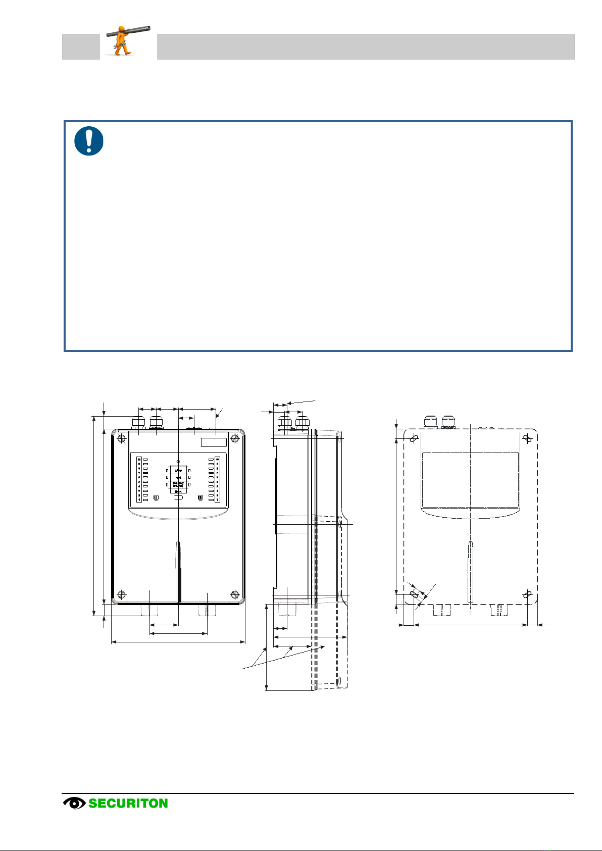
2.2 Dimensioned drawing / drilling plan for detector housing
Fig. 1Dimensioned drawing, ASD 535 detector housing drilling plan
Position of M25
screwed cable glands
and air outlet
Position
of air outlet
Space requirement
for offset mounting
of the housing cover
for commissioning
and maintenance
27
(76)
27
35
22
148
57
23
(171)
348 approx. 26
(397)
265
114
35 44 74
31
225
20 20
310 1919
10
6,5

Mounting
12 / 40 ASD 535, Mounting and installation, T 140 333 d en
2.3 Material for the sampling pipe
Notices
Tube materials and fittings must satisfy the requirements of at least Class
1131 of EN 61386-1
. Document
T
131 194 lists materials that meet this standard; it is part of the device approval of the ASD
535 according to
EN
54-20.
Other materials do not conform to the EN
54-20 standard and may be used only if the manufacturer’s written con-
sent has been obtained and the following conditions are met.
•
Compression resistance = at least 125 N (EN 61386-1)
•
Shock resistance = at least 0.5 kg, fall height of 100 mm (EN 61386-1)
•
Temperature range = at least –15°C to +60°C (EN 61386-1)
•
Tube inner diameter = 19 to 22 mm
•Bend radius = at least 30 mm.
The tube material is available as different plastics and metals. The individual plastic tube parts are usually glued. The flexible
tube material for equipment monitoring is pluggable. The metal tubes are connected by means of press fittings.
The rigid plastic tubes can be shaped by heating them. The tubes can be painted a different colour, whereby attention must be
paid to the chemical compatibility of the paint to the tube.
The following materials are available:
Material
Connection method
PVC (polyvinyl chloride, contains halogen)
Gluing
ABS (acrylonitrile-butadiene styrene, contains no halogen)
Gluing
PA (polyamide, contains no halogen)
Plug-in connection
Copper
Press fitting
Stainless steel
Press fitting
Notices
•
The two materials that use glues (PVC and ABS) must not be combined, since different adhesives are used.
•
Transitions from PVC or ABS to PA materials (flexible tube parts) are possible with special adhesive screw
junctions.
•
PVC produces corrosive and toxic gases if burned or improperly disposed of. The use o
f PVC materials
should therefore be limited to where it is expressly permitted by the operator of the installation. In applications
where halogen-
free plastics are prescribed, ABS or PA materials must be used for laying the sampling pipe.
Country-specific guidelines and regulations must be observed.
•
The adhesives and cleaning agents used for connecting PVC and ABS materials contain solvents and are
combustible. For this reason, prior to working with these materials it is imperative to read and observe the
safety instructions and information provided by the adhesive supplier.
A list of the available materials for the sampling pipe (tubes, fittings etc.) for the ASD 535 is available in a separate docu-
ment (T 131 194).

Mounting
ASD 535, Mounting and installation, T 140 333 d en 13 / 40
2.4 Mounting the detector housing
Notices
•
Mounting work on the detector housing is best done without fitted smoke sensors.
•
The smoke sensors are always installed in the detector housing just when the ASD
535 is commissioned (see
Sec. 3.3).
•
Depending on the situation (e.g. if there is a long time between mounting and commissioning or if the envi-
ronment is very dusty due to construction for example), the housing cover should be kept closed until com-
missioning the device.
•
Mounting of the detector housing within hostile environments (according to Australian Standard AS 1603.8) is
not allowed.
The detector housing should always be kept in the room to be monitored. If this is not possible, it must be guaranteed that the
detection housing is located in a room which has the same air pressure or – for air-conditioned rooms – the same climate and
pressure zone. In applications where the sampling pipe and detector housing are mounted in different climate zones, a return
sampling pipe to the monitored area is required. The return line can be adapted after removing the air outlet pipe plug on the
ASD 535 housing. In this context, see also Sec. 2.4.2 and 2.4.3. The maximum length of the return line must not exceed 20 m.
In areas with significant temperature fluctuations of more than 20°C, special adjustments (larger airflow window, longer delay
time etc.) may have to be performed for the sampling pipe and on the detector housing. This also applies to temperature dif-
ferences of more than 20°C between sampling pipe and detector housing.
An easily accessible installation location should be chosen so that the detector housing can be worked on without aids such as
ladders and scaffolding. The ideal installation height of the detector housing is about 1.6 m above the ground (top edge of the
detector housing).
On the entry side of the sampling pipes a minimum distance of 20 cm from building elements should be maintained (see Fig.
1) to enable fastening the housing cover (commissioning and maintenance work). On the entry side of the supply cable, 10 cm
distance is sufficient.
When determining a location for the detector housing, take into account that the noise caused by the fan may in some in-
stances be disturbing. If no suitable location is available for the detector housing, it may be necessary to mount it in an acous-
tically insulated cabinet (e.g. ASD sound insulation housing). If air recirculation in the same climate zone as the sampling pipe
is necessary, it can be implemented by means of a tube piece out of the acoustically insulated cabinet. The pipe piece exiting
from the acoustically insulated cabinet (transition) must be properly sealed. When using the ASD sound insulation housing, an
M32 cable screw union is used for the transition. Contact the manufacturer for more information about the ASD sound insula-
tion housing.
Mounting
14 / 40 ASD 535, Mounting and installation, T 140 333 d en
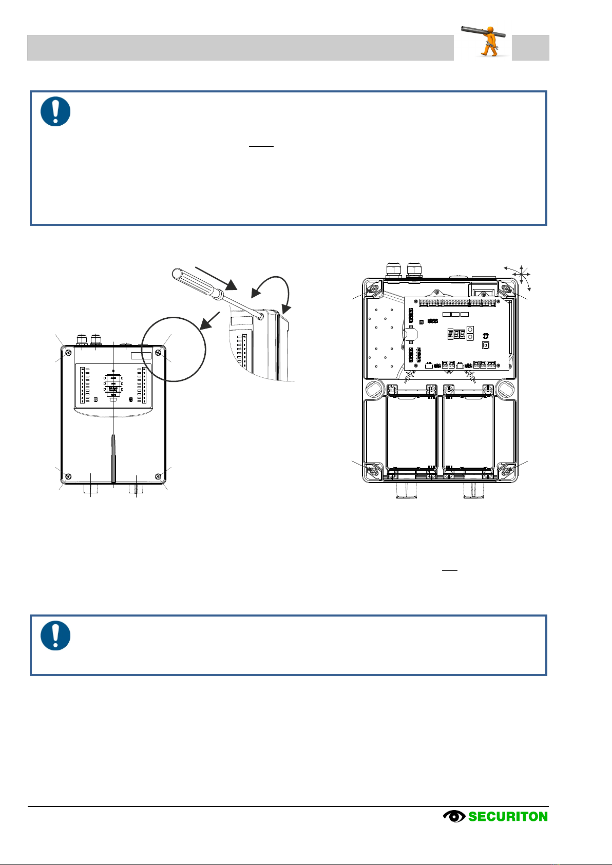
2.4.1 Opening and closing the detector housing
Notices about opening and closing
•
To open the detector housing, use a flat-blade screwdriver no. 5 (8 mm). Smaller flat-
blade screwdrivers
may damage the material of the rotary snap locks.
•
To use the rotary snap locks, press firmly with the screwdriver toward the housing base and then turn
90°.
The position of the lock slit shows the current state (see Fig. 2):
⇒approx. 45° angled toward detector housing corner = closed
⇒approx. 45° angled toward detector housing edge = open
The rotary snap locks must snap into place.
•
The housing cover (control unit) is connected to the Main Board by a flat cable
. Make sure that when the
housing cover is lifted away the flat cable does not become damaged.
Fig. 2Opening, closing and fastening the detector housing
After the detector housing is open, the four mounting holes in the housing base are accessible. To facilitate mounting work,
remove the entire housing cover of the detector housing (including control unit). To do that, pull off the 10-pin flat cable con-
nector from the AMB 35 Main Board.
The detector housing is fastened with the four supplied Torx wood screws (Ø 4.5 x 35 mm) and the four U-washers
(Ø 4.3/12 x 1 mm), “A”. Use a Torx T20 screwdriver to insert and tighten the screws.
The positions of the fastening holes are seen in dimensioned drawing Fig. 1. When fastening to masonry, the supplied S6
dowels are used.
Notice
When mounting several ASD
535 units next to each other, it is important to ensure that the mounting holes are
drilled precisely
. The device can be moved a maximum of ±2
mm horizontally and vertically to correct the
mounting position. A rotation correction of approx. ±5 mm is possible.
closed closed
closed closed
open open
open open
Opening / closing
A
A
AA
X/Y = 2± mm
U = 5± mm
X
UY
Locking
1. 2.
press turn

Mounting
ASD 535, Mounting and installation, T 140 333 d en 15 / 40
2.4.2 Mounting positions of the detector housing
In principle the detector housing can be mounted in the X, Y or Z axis. Because of the indicator elements labelling, however,
mounting in the Y axis is advisable (vertical, control unit up). The sampling pipes are then inserted into the detector housing
from below. This makes it easier to conduct pipes to accessory parts such as filter box / filter unit and water separators, which,
for physical reasons, should always be below the ASD detector housing. If introducing the sampling pipes into the detector
housing from above is unavoidable, the detector housing can be turned 180° and mounted (control unit down). So that the con-
trol unit labelling is not upside down, the labelling strips of the control unit can be turned accordingly (see Sec. 2.4.4).
The allocation of the tube networks to the smoke sensors is permanently preset and is recognisable by the identification (ribs)
on the tube inputs (Iand II). To prevent dirt from entering, the detector housing is delivered with fitted pipe plugs (tube network
I and II entries). Similarly, all cable screw unions are closed. The pipe plug is removed on entry I for ASD 535-1 and -3 and on
entry II for ASD 535-2 and -4. For ASD 535-1 and -3 with only one tube network, the pipe plug on entry II is not removed. If
there is a return sampling pipe in the monitored area, it can be directly connected to the detector housing in place of the air
outlet pipe plugs.
Fig. 3Mounting position and pipe entries on the detector housing
Notices about pipe entries
•
The entry openings in the detector
housing are designed so that the sampling pipe only has to be inserted
(conical opening). Using an adhesive agent on the sampling pipe should be done only in special cases and af-
ter consulting with the manufacturer.
•
On the ASD 535-1 and -3 the pipe plug must remain on entry II.
•
The air outlet pipe plug (with openings) may be fitted only in the air outlet opening.
•The pipe plugs must not be glued in the ASD housing (connector).
remove
Pipe network II
Incoming
sampling pipes
from below
Pipe network I
remove
Pipe network II
Return line
of sampling pipe
Pipe network I
Tube entry
from above
remove
Pipe network II
Pipe network I
Turn labelling
strips
remove
Pipe network II
Incoming
sampling pipes
from above
Pipe network I

Mounting
16 / 40 ASD 535, Mounting and installation, T 140 333 d en
2.4.3 Removal of the air outlet pipe plug
Insert the blade of a flat-blade screwdriver no. 2
(4 mm) into one of the side recesses of the air outlet
pipe plug. A slight prying movement toward the ASD
housing releases the pipe plug.
Fig. 4Removal of the air outlet pipe plug
2.4.4 Turning the labelling strips
To turn the labelling strips, open the detector housing
and completely remove the cover from the device
(undo the flat cable).
Depending on the device version, there is a different
number of labelling strips printed on both sides in the
control unit:
•ASD 535-1 = 1 x “A”
•ASD 535-2 = 1 x “A”
•ASD 535-3 = 1 x “A” and 1 x “B”
•ASD 535-4 = 1 x “A” and 2 x “B”
The labelling strips can be pulled out of the control unit
by their tabs and after turning over inserted again into
the holder.
Fig. 5Turning the labelling strips
Carefully twist off in the
direction of the arrow
Recess for screwdriver
View of cover from inside
BCB 35 / ACB 35
(gez. ACB 35)
State indicator
Smoke level indicator
Normal
mounting
Normal
mounting
B
B
A
A
A
B
B
Upside down
mounting
Upside down
mounting
Mounting
ASD 535, Mounting and installation, T 140 333 d en 17 / 40
2.5 Mounting sampling pipe
2.5.1 General information
Mounting and installation is based on the “Planning” section in technical description T 131 192. Deviating from the layout of the
sampling pipe and sampling holes (also outside the limits calculated with “ASD PipeFlow”) is permissible only with the consent
of the manufacturer.
The sampling pipe can be hard PVC or halogen-free ABS material, depending on requirements. In special applications (e.g. in
an extremely corrosive environment) other pipe materials may be used subject to the specifications in Sec. 2.3.
Notice about pipe installation / modification
The performance of this system is dependent upon the sampling pipe. Any extensions or modifications to the d
e-
signed installation may cause
improper operation. The operational effects of such changes shall be verified. Sec-
tion “Planning” (T
131 192) must be considered in any case.
The calculation software “ASD PipeFlow” is available
from the manufacturer.
2.5.2 Mounting with PVC tubes and fittings
As a rule, when the installation operator does not demand halogen-free installation, sampling pipe can be laid out with hard
PVC tubing. When PVC tube material is installed, the individual tube parts are glued together with a special PVC glue (e.g.
Tangit for PVC). The glue manufacturer’s instructions must be followed. Before gluing, use household paper to remove dust
and grease deposits from the surfaces to be glued (do not use textile cloths). If the tube parts are very dirty, a cleaning agent
specified by the glue manufacturer may have to be used.
Notices
•
The adhesives and cleaning agents used for connecting PVC materials contain solvents and are combustible.
For this reason, prior to working with these materials it is imperative to read and observe the safety instruc-
tions and information provided by the adhesive supplier.
•The two glueable materials – PVC and ABS – must not be combined, since different adhesives are used.
2.5.3 Mounting with ABS tubes and fittings
If required, halogen-free ABS material can be used for the sampling pipe. When ABS pipe material is installed, the individual
tube parts are glued together with a special ABS glue (e.g. Tangit for ABS). The glue manufacturer’s instructions must be fol-
lowed. Before gluing, use household paper to remove dust and grease deposits from the surfaces to be glued (do not use tex-
tile cloths). If the tube parts are very dirty, a cleaning agent specified by the glue manufacturer may have to be used.
Notices
•
The
adhesives and cleaning agents used for connecting ABS materials contain solvents and are combustible.
For this reason, prior to working with these materials it is imperative to read and observe the safety instruc-
tions and information provided by the adhesive supplier.
•The two glueable materials – PVC and ABS – must not be combined, since different adhesives are used.
Mounting
18 / 40 ASD 535, Mounting and installation, T 140 333 d en
2.5.4 Mounting with metal pipes and fittings
Metal tubes (copper, stainless steel) are connected using press fittings according to the manufacturer’s instructions. For this
purpose, commercially available radial pressing tongs (e.g. REMS radial pressing tongs) with the appropriate V pressing con-
tours can be used.
2.5.5 Linear expansion
Due to the large linear temperature expansion coefficient of plastics, special attention should be given to linear expansion (ex-
tensions and shortenings) of the sampling tube. An increase in temperature causes lengthening; a decrease in temperature
causes the tube to become shorter. The importance of taking linear expansion into account increases as the temperature at
the time of installation deviates from the usual operating temperature.
Linear expansion can be calculated as follows:
Calculation:
∆L =
L x ∆T x α
∆L
=
Linear expansion in mm
L
=
Length in meters of the sampling pipe between two fixed points
∆T
=
Temperature change in °C
α
=
Linear expansion coefficient in mm/m°C
for PVC = 0.08
for ABS = 0.10
Example: sampling pipe length 20 m, expected temperature change 10°C, material PVC:
Calculation:
∆L =
20 x 10 x 0.08
=
16 mm
Notice
For straight layout the linear expansion can be up to
176 mm over the total sampling pipe length (110
m) within
the permitted temperature fluctuation range (20°C). It must therefore be ensured that the sampling pipe can
“work” (slide) in the clips and fastening clamps. A distance of 200
mm (0.2 m) should be maintai
ned between the
last clip or fastening clamp to the end cap.
Mounting
ASD 535, Mounting and installation, T 140 333 d en 19 / 40
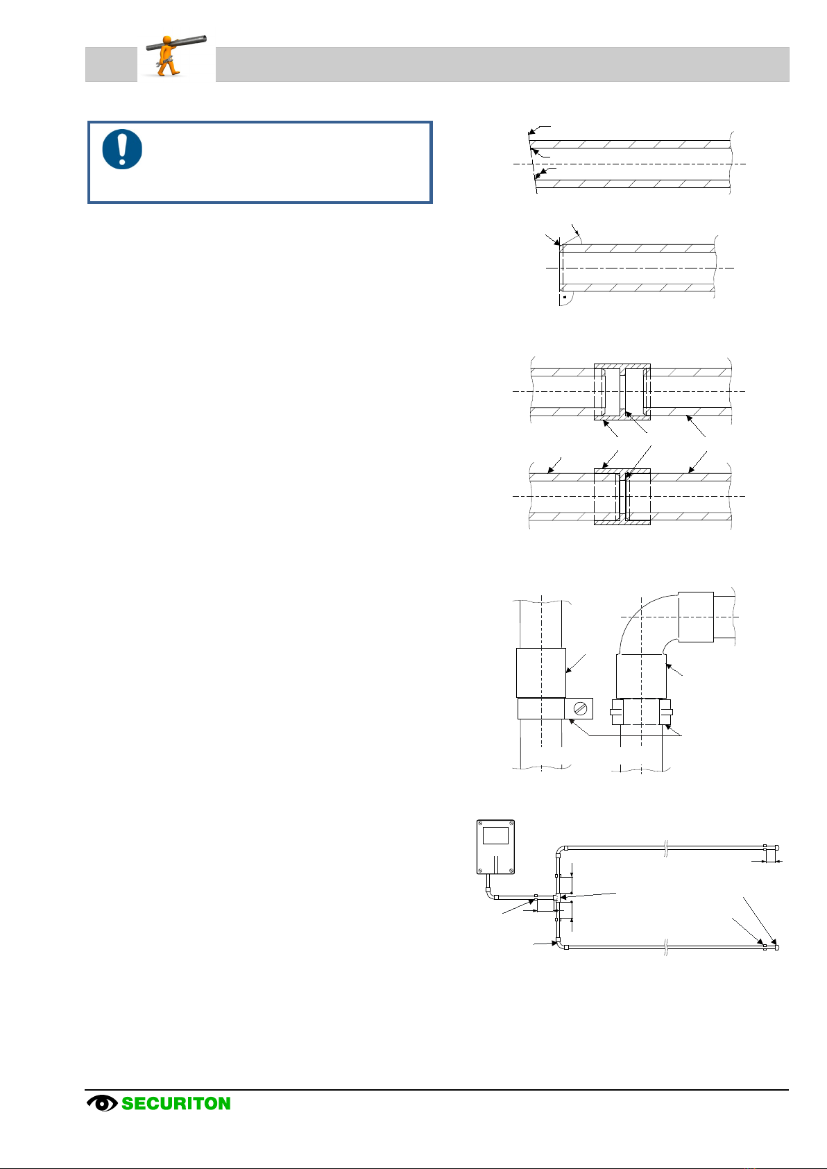
2.5.6 Mounting the sampling pipe
Notice
When mounting the sampling pipe, the points b
e-
low must be observed and adhered to (see
Sec. 2.5.5):
•Clips and pipe clamps at 1 m intervals are used to fasten
the sampling pipe.
•The tubes must be cut with a pipe cutter to required
lengths. In doing so, ensure that the cut is at a right-angle
to the tube axis. Any projecting burrs must be removed
Fig. 6.
•The ends of the individual tube pieces are to be slightly
angled with a suitable tool, e.g. slightly bevel with a pipe
peeler, Fig. 6.
•The individual pipe sections are connected to each other
with fittings. Depending on the used tube material, gluing
as described in Sec. 2.5.2 and 2.5.3 or pressing as de-
scribed in Sec. 2.5.4 is used. The tubes are pushed into
the fittings to the stop, Fig. 7.
•The connection points must be absolutely sealed to pre-
vent the wrong air from entering.
•For vertically arranged sampling pipe or parts thereof (e.g.
in a riser or high-rack storage building) make certain that
the tubes cannot slide down (fasten clips directly under fit-
tings as shown in Fig. 8).
•The sampling pipe must be fastened so that the tube can
“work” in the clips (linear expansion, see Sec. 2.5.5).
•Beginning at the branching points of the sampling pipe, a
distance of at least 0.2 m must be maintained from the T-
piece to the clips, Fig. 9.
•For changes of direction in space surveillance installations,
it is advisable to use 90° bends rather than 90° angles,
Fig. 9.
•When using flush mounting or in false ceilings, it must be
ensured that the tubes are not able to vibrate.
•How the tubes are laid out – especially for flush mounting
– must be precisely entered in the dimensional data in the
installation plans.
Fig. 6Cutting the tubes
Fig. 7Joining the tubes
Fig. 8Vertical sampling pipe
Fig. 990° bend, branching point
Angled cut
Pressure points
Burrs
Bevel approx. 30º
wrong
correct
wrong
correct
Tube Sleeve Stop Tube
Sleeve
Clip
below
fitting
Vertical sampling pipe
90º arc
ASD 535
0,2 m
0,2 m
0,2 m
0,2 m
T-piece End cap
Clip
Clip
90º arc

Mounting
20 / 40 ASD 535, Mounting and installation, T 140 333 d en
2.5.7 Mounting for equipment monitoring
When mounting equipment-monitoring systems (EDP installations, electrical cabinets etc.), plastic tube materials are always to
be used. Further, the same guidelines as described in Sec. 2.5.6 apply.
All air outlet openings of the monitoring devices have to be used for equipment monitoring. Please note that an ASD 535 can
be fitted with a maximum of six sampling fixtures.
Whenever possible, sampling pipe and detector housing are always fastened directly to the object to be monitored.
2.5.7.1 Screw-free fastening of the sampling pipe
For screw-free fastening of sampling pipe parts (sampling fixtures) the click pipe clamps are used. This makes it possible to
quickly remove the sampling fixture or the sampling pipe during maintenance work on the monitored objects.
The click pipe clamps are screwed onto the support rails by means of threaded plates.
The support rails are best fastened at a right angle to the pipe axis to ensure precise positioning of the sampling pipe (sam-
pling fixture).
Double-sided adhesive tape is used to fasten the support rails in the desired position on the object, Fig. 10.
Prior to using the double-sided adhesive tape, the adhesion surfaces should be cleaned with a non-aggressive cleaning
agent (e.g. soap suds or similar).
Using a cable binder instead of the double-sided adhesive tape is also possible.
Fig. 10 Screw-free fastening of a sampling fixture
EDP cabinet Ventilation slot Sampling fixture
Tube Click pipe clamp
Movement of the tube
in the click pipe clamp
Support rail
Double-sided
adhesive tape
Movement in the
support rail
M4 threaded plate
Detail A Detail A
Other manuals for ASD 535
1
Table of contents
Other Securiton Smoke Alarm manuals


