Seresco NG Series User manual

SerescoDehumidifiers.com
INSTALLATION MANUAL
DRY COOLERS
NG Series

Table of Contents
General Information ........................................................................................................................................2
Operating Safety (Warnings, Cautions, and Notes)................................................................................................... 2
Reference and Additional Information...................................................................................................................... 2
Delivery and Storage. .......................................................................................................................................4
Receiving Checklist..................................................................................................................................................... 4
Shipping Damage Handling........................................................................................................................................ 4
Storage....................................................................................................................................................................... 4
Mechanical Installation ....................................................................................................................................5
Lifting and Rigging...................................................................................................................................................... 5
General Mechanical Installation Requirements ........................................................................................................ 6
Mechanical Installation –Special Cases .................................................................................................................... 7
Piping Connection ............................................................................................................................................9
Piping General Considerations .................................................................................................................................. 9
Electrical Connection: Power and Control........................................................................................................ 12
Electrical Connection General Considerations ........................................................................................................ 12
Dry Cooler Install Manual 2October 2020
General Information
This manual provides basic information about various installation aspects of the applicable equipment and its
additional and auxiliary systems and devices.
Important information regarding operation and maintenance of said equipment is normally provided with the
equipment and can also be obtained from the manufacturer (see Contact Us below).
Operating Safety (Warnings, Cautions, and Notes)
FOR YOUR SAFETY: READ BEFORE PERFORMING ANY INSTALLATION OR OTHER TASKS!
Only qualified technicians should install, operate, maintain or service mechanical equipment!
Make sure to read this manual before performing any installation tasks to familiarize yourself
with the equipment as well as with any potential hazards. Always exercise caution!
Beware of chemicals!
Equipment may contain water/glycol mixtures –refer to equipment data for more details.
The following warnings, cautions, and notes appear throughout this manual and referenced documentation
whenever special care must be taken to avoid potential hazards that could result in equipment malfunction or
damage, personal injury, or death.
Reference and Additional Information
For safe, efficient and problem-free operation, it is critical to handle the equipment and related systems and
components properly at each step - from receiving and storage to installation and start up. Relevant information
can be found in the respective documents (Operation and Maintenance Manual etc.) provided with the
equipment.
WARNING
Indicates a potentially hazardous
situation which could result in
serious injury or death if handled
improperly.
CAUTION
Indicates a potentially hazardous
situation which could result in
moderate injury or equipment
damage if handled improperly.
Note
Indicates a situation that could
result in equipment damage or
improper/ineffective operation if
handled improperly.
WARNING! Any work (installation, start up, service, maintenance, repair, etc.) on any mechanical
equipment must be performed in accordance with respective manufacturer recommendations as well as
submittal documentation, local Codes and Regulations, and appropriate field practices. Failure to do so could
result in personal injury, equipment damage or malfunction, and will void equipment warranty. Only qualified
and properly trained individuals should perform tasks on this equipment.
October 2020 3Dry Cooler Install Manual
Warranty
The manufacturer standard warranty statement can be found in the Operation and Maintenance Manual,
provided with the equipment (also could be requested from the manufacturer).
Contact Us
Seresco
1071 Ages Drive
Ottawa, ON K1G 6L3
Canada
SerescoDehumidifiers.com
1-833-DAS-POOL (327-7665)
Schedule / Modify a Start-up:
Start[email protected]
Inquire about Warranty:
Warranty@DehumidifiedAirServices.com
Order Parts:
Parts@DehumidifiedAirServices.com
All Other Product Support:
Support@DehumidifiedAirServices.com
Attention: Warranty Conditions and Coverage.
NOTE. The equipment is provided with comprehensive conditional warranty coverage. Any warranty work
sought to be reimbursed must be approved by the manufacturer Customer Support Team prior to work
commencing. Installation, start up, maintenance etc. are not within warranty scope.
Refer to the manufacturer standard warranty statement for more details on warranty conditions, scope and
coverage.
Dry Cooler Install Manual 4October 2020
Delivery and Storage.
Receiving Checklist
It is highly recommended to thoroughly check for both visible and concealed damage upon the equipment arrival
and before signing the receiving papers.
As applicable:
Visually inspect exterior of the equipment for damages (scratches, dents, missing elements, etc.)
Verify the proper operation of latches and hinges on all access doors and panels
Inspect all coils for damage to the fin surface coating, headers or coil connections
Inspect the fan housings for any foreign objects
Inspect and test all piping for possible shipping damage
Check the tightness of bolts, screws and other fasteners
Shipping Damage Handling
Manufacturer standard shipping term is FOB (freight on board), meaning that the equipment belongs to the
customer as soon as the delivery truck leaves the factory.
Shipping Damage Handling Instructions:
Note the damage in detail on the freight bill and bill of lading.
Take clear photographs of the damaged components, areas, portions of the equipment etc.
Obtain a claim form from the carrier, fill it out, and return it promptly. Report all claims of shipping damage to
the carrier immediately and coordinate a carrier inspection if necessary.
Contact manufacturer Customer Support team (see Contact Us above) to notify of the noted damage.
oHave the equipment serial number on hand to provide to Customer Support. The serial number can
be found on the equipment’s main label or bill of lading.
oNote: it is the receiver's responsibility to provide reasonable evidence that damage was not incurred
after delivery.
oDo not attempt to repair the equipment without consulting with manufacturer Customer Support
team.
Storage
•Shipping protection material is provided by the manufacturer for shipping purposes only!
•If long-term storage is required, warranty aspect should be considered. Refer to the Warranty section of
Operation and Maintenance Manual for more details. Please contact manufacturer should there be any
questions.
Note: manufacturer is not responsible for any shipping damage. Should the equipment arrive damaged,
follow the instructions below to resolve the situation. Delivery cannot be refused on the basis of shipping
damage.

October 2020 5Dry Cooler Install Manual
Mechanical Installation
Lifting and Rigging
Use spreader bars for lifting to prevent equipment damage.
oSpreader bar usage/positioning, shown on Pic. E.1, is only an example! Determine spreader bar set
up (configuration, cables location/positioning etc.) based on the particular equipment to be lifted.
oUse equipment lifting brackets at the base frame.
Each of the lifting cables (chains or slings) must be capable to support the weight of the entire equipment.
Determine the approximate centre of gravity before lifting. See equipment design drawings in the submittal
documents for the total weight and weight distribution.
Lifting cables (chains or slings) may not be of the same length. Adjust as necessary for an even lift.
Do not lift equipment in windy conditions.
Do not raise equipment overhead with personnel below.
Test lift the equipment 24 inches to verify proper operation of lifting machinery and positioning of lift points
such that the lifted equipment is level.
WARNING! Lifting and rigging must be
done by trained professionals in accordance with
proper lifting techniques and safety procedures.
Proper lifting machinery and tools and safety
equipment (PPE) must be used.
Improper lifting may cause equipment damage,
serious injury, or death. Manufacturer is not
responsible for the improper use of lifting
equipment or improper lifting practice.
WARNING! All work must be done by qualified personnel in accordance with local and national Codes,
Standards and Regulations as well as respective design and submittal documentation and manufacturer
recommendations.
CAUTION! Obtain all necessary documentation (manufacturer manual(s), submittal documentation,
drawings, etc.) and familiarise yourself with it before performing installation or any other related tasks.
Pic. E.1
Dry Cooler Install Manual 6October 2020
General Mechanical Installation Requirements
Equipment should be installed in accordance with respective local Codes and Regulations as well as applicable
submittal documentation.
General Placement of the Equipment
Equipment must be installed on a firm, levelled surface, with provision for vibration absorption.
Service and operational clearances to the equipment must be always maintained:
oAccess to ALL doors, panels, covers, valves, disconnects etc. must not be restricted. Some installations
may require cat-walks or other means of access to otherwise restricted side of the equipment.
oGeneral Clearance: up to 36” all around and up to 96” above fan(s) for proper operation, service and
maintenance (for equipment-specific data, refer to respective submittal documentation).
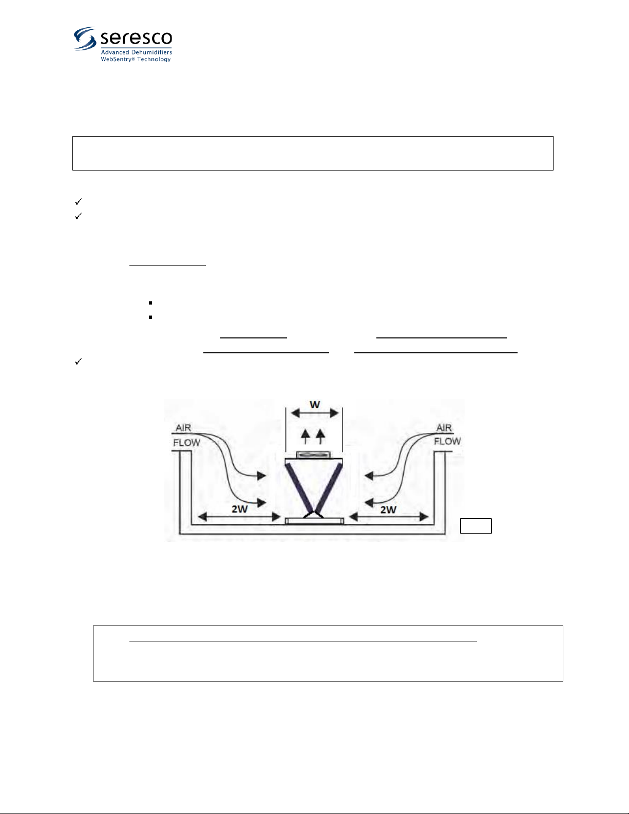
oEquipment installed in a pit (surrounded on all four sides by walls, structures, etc. – see Pic. E.2):
Avoid such installation as much as possible!
If such installation cannot be avoided, the following must be maintained:
•the min. clearances must be increased to double width of the equipment all around;
•surrounding structures’ height must not exceed the height of the equipment.
Anchor (secure, fasten etc.) light-weighted equipment to the horizontal mounted surface (concrete pad etc.).
oThis applies mostly to NG series fluid coolers models NG-Z, NG-V-01, NG-V-02, NG-V-11 and NG-V-12.
NOTE: distance between the fluid cooler and the other equipment it serves affects the connecting pipe line set
(length, size etc.). Consider it prior to finalizing the placement of the equipment! Before placing the equipment,
ensure that resulting pipe set selection (length, diameters etc.) are acceptable.
NOTE. For equipment-specific data (dimensions, clearances, accessibility, etc.) refer to equipment submittal
documentation, Operation and Maintenance Manual, and equipment labels and stickers.
NOTE. Do NOT exceed distance limitation between the fluid cooler and equipment it serves –it may result in
equipment incorrect operation and/or failure. Before finalizing the fluid cooler placement/location, refer to
respective equipment data (including submittal documentation) and Equipment Piping chapter of current
manual (see further). Contact the manufacturer if needed.
Pic. E.2

October 2020 7Dry Cooler Install Manual
Mechanical Installation –Special Cases
The placement requirements outlined above apply to all models of NG series fluid coolers.
Model NG-Z Fluid Coolers’ Mounting/Support Set Field Assembly
The NG-Z model fluid coolers can be provided in vertical or horizontal airflow configuration and may require field
assembly of respective mounting/support set (legs):
Vertical airflow configuration (for mounting on a horizontal surface such as ground, roof, etc.) –see Pic. E.3:
Uncrate/unwrap the equipment and legs.
Install the four provided legs (a) onto the equipment (leg is to be placed inside in the corner)
oDouble cooler (b) would have six legs provided –place two additional legs in the middle –refer to
picture.
Align all four holes in each leg and equipment corner and attach legs with provided bolts, washers (legs have
factory-installed nut-certs); tighten all bolts.
Ensure that the cooler is levelled and firm; affix the legs to the surface (concrete slab, etc.); anchors/fasteners
for surface mounting are NOT included.
Pic. E.3
Dry Cooler Install Manual 8October 2020
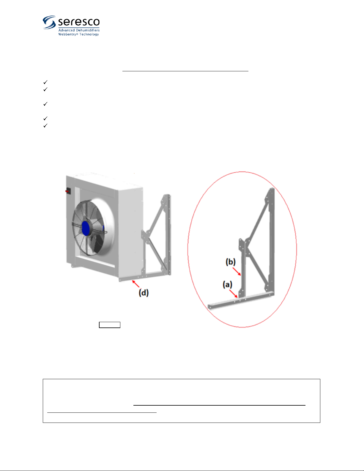
Horizontal airflow configuration (for mounting on a vertical surface such as wall etc) - see Pic. E.4. In this case, use
the same mount kit as above. Note that the mount legs are assembled slightly differently.
Uncrate/unwrap the equipment and mounting kit.
Assemble left and right mount legs as shown with provided bolts, nuts, and washers (except for joint point (a) –
it must be bolted to the cooler box)
Align respective holes in cross-piece (b) and the holes in the equipment and attach them with provided bolts,
nuts, and washers.
Attach rear support braces to the cooler with provided self-tapping screws (d)
Ensure that the assembly is straight, square, and sturdy; tighten all bolts.
oEnsure that the cooler is levelled and firm; affix mount legs footings to the surface (wall, etc.);
anchors/fasteners for surface mounting are NOT included.
ATTENTION! Cooling Fluid Lines Sweating!
Under certain conditions (namely –when the cooling fluid lines’ outer surface drops below dew point of the
surrounding air, particularly inside the facility), said lines may “sweat” as condensation forms on their surface.
Should this occur, it is recommended to insulate the piping to prevent condensation.
Pic. E.4
October 2020 9Dry Cooler Install Manual
Piping Connection
Piping General Considerations
Refer to the equipment main label and stickers at lines/piping termination to verify respective connecting
lines’ sizes, flow directions (IN/OUT) and media type (water, glycol/water mixture and ratio etc.)
oFlow direction stickers at respective piping stubs refer to the equipment it’s attached to: IN –media
(water, glycol etc.) entering the equipment, OUT –leaving the equipment.
oSelect the line/piping size based on the equipment documentation (labels, drawings, etc.). Note that
diameters of the piping stubs/connections may be different from the required line size.
Use proper materials and pipe joining methods, respective to given system (system media, pressure, etc.).
Use proper installation field practices and Code(s) requirements (proper piping support, no pipe-to-edge
contact, grounding/bonding, insulation, pressure testing, charging/filling, etc.)
As/where needed, ensure that proper isolation and balancing means (valves, circuit setters, etc.) are in place.
Provide proper means for priming (filling), draining and aerating (bleeding the air from the system): install
automatic air bleeding valve(s) at each local top point of the system and drain/priming valves at the lowest
point(s) of the system.
Line Set Selection and Sizing
•Refer to fluid cooler (and/or equipment it serves) data (main label etc.) for line set typical diameter (both lines,
supply and return, are normally of the same size).
oTypical line set diameter accounts for system proper operation if line set total equivalent length does
not exceed (approx.):
200’ – for NG-V-02 fluid cooler model*
300’ – for NG-V-12 fluid cooler model
450’ – for other fluid cooler models
oIf the total equivalent length exceeds above value, the line set diameter must be increased to next size
(e.g., step up diameter from 1 ¼” to 1 ½”). Contact the manufacturer for more details, if needed**.
* in some cases, NG-V-02 fluid cooler model may accommodate higher total equivalent length with typical diameter –
contact the manufacturer for details.
** typically, the fluid cooler is either provided with the pump package or serves the equipment, equipped with its own
pump, therefore no additional pump is needed. However, in some cases additional pump may be required. Contact the
manufacturer if needed.
•Standard recommended pipe and fitting materials are PVC, steel and copper. Other materials may also be
suitable –refer to material applicability according to given application (system media, max working pressure,
temperature, etc.).
WARNING! All work must be done by qualified personnel in accordance with local and national Codes,
Standards and Regulations as well as respective design and submittal documentation and manufacturer
recommendations.
CAUTION! When connecting the equipment to external mechanical and electrical systems, refer to
submittal documentation and equipment labels and stickers for piping connection details.
Dry Cooler Install Manual 10 October 2020
Piping
Ensure proper piping support and bracing is in place –fluid
cooler pipe terminations do not provide structural support
for pipe line set.
Follow proper piping practices (cleaning, sanding, reaming,
wet-ragging during soldering, etc.) and bonding methods,
respective to pipe and fittings material (soft soldering,
gluing, etc.).
Install valves/devices to isolate, drain, charge and remove
the air from the fluid cooler and line set.
oFluid cooler typically is not provided with isolating
valves –install as needed.
oInstall drain/charge valve(s) at the lowest point(s) of
the line set and the equipment; install air bleeding
valve(s) at the top point(s) of the line set (see Pic.
G.1(A) and (B)); fluid cooler would typically have
drain/charge valves installed at their lowest
point(s).
oPump package (if fluid cooler is equipped with or
provided separately with one) typically includes
pump with pressure gauges and expansion tank;
otherwise –determine, if the circuit requires
expansion tank and other devices.
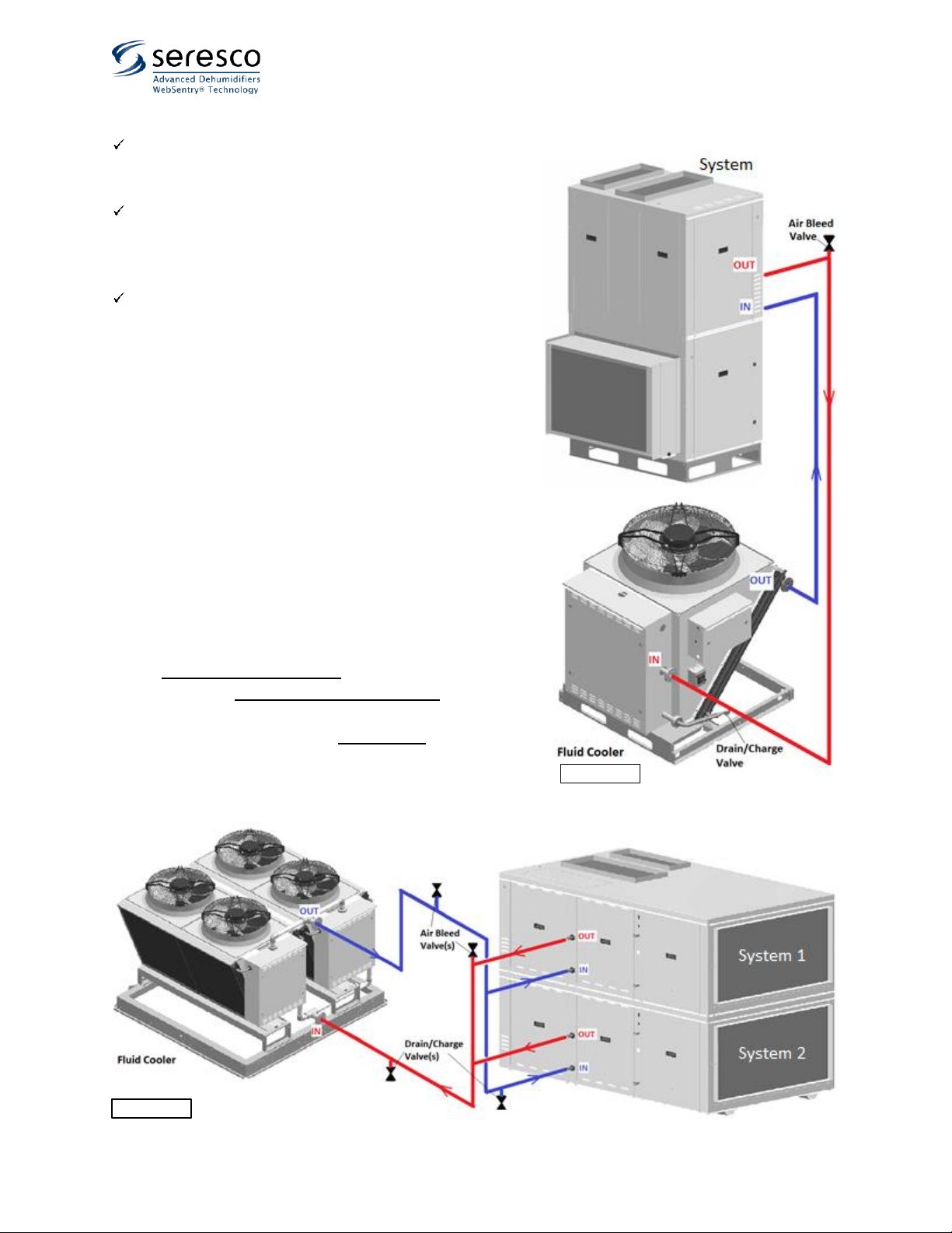
Pic. G.1 (A) shows typical piping schematic for single fluid cooler
serving single system/cooling circuit. Piping schematic for single
fluid cooler serving multiple systems/cooling circuits is shown on
Pic. G.1 (B).
NOTE: the given schematics are example only - the design,
provision and installation of actual fluid cooler piping is not
manufacturer’s responsibility and is to be done by a third party.
Pic. G.1 (A)
Pic.G.1 (B)
October 2020 11 Dry Cooler Install Manual
Pressure Testing and Charging
•Refer to the fluid cooler (and/or equipment it serves) data (main label, submittal documentation etc.) for
operating pressure and cooling media selection.
oOne of the typical media is a mixture of food grade propylene glycol (with rust inhibitors added) and
distilled water is used as a cooling fluid. The mixing ratio is typically 30-35% glycol; however, a higher
glycol concentration (e.g., 50%) could be used for northern application –refer to the equipment
submittal documentation.
oTo calculate approximate (!) Total System Volume (amount of fluid required for system charging), add
Internal Fluid Cooler Volume (see submittal documentation) to Line Set Volume (calculate based on the
used pipe diameter and line set actual length). Increase calculated Total System Volume by 3-5% - final
charge of the system would be determined during the charging (see below).
•Charge system at its lowest point and bleed the air out at the system top point(s); depending on the circuit
configuration, charging at multiple lowest points (at fluid cooler and the equipment it serves) may be required.
oUse a separate charging pump. The fluid cooler pump(s) (if present) are selected/designed to maintain
fluid circulation and not be used for charging. Ensure fluid is clean, free of any debris etc.
oEnsure thorough air removal from the circuit –airlocks will prevent system from operating properly.
oEnsure that static pressure at the highest point of the system is at least 15-20 psi. Verify it after bleeding
all the air from the system.
Dry Cooler Install Manual 12 October 2020
Electrical Connection: Power and Control
Electrical Connection General Considerations
Select power supply wire gauge and, as/when needed, external power apparatuses (disconnects, breakers,
etc.) according to equipment electric data (MCA, MOP, etc.), provided on the main label, as well as respective
local and national codes and regulations.
Equipment is provided with its respective wiring diagrams, depicting equipment internal wiring and terminals
for external connection (power supply, control terminals, etc.) –refer as needed.
Properly seal all penetrations made/used in the equipment panel/junction box. Failure to due so may result in
water/humid air infiltration that could lead to equipment’s electrical apparatuses malfunction or damage.
Ensure that all metal shards and filings are swept to avoid possible corrosion or damage to electrical
components. Ensure that wires are properly protected/isolated from the equipment cabinet sharp edges, hot
surfaces, etc.
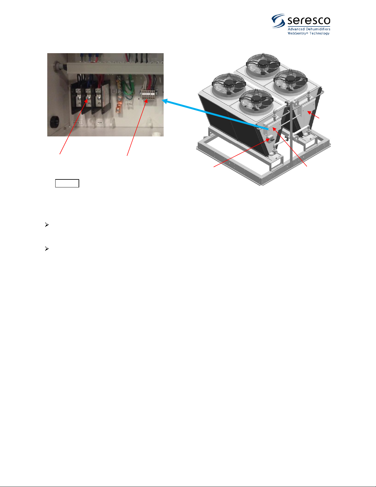
Equipment Main Power Connection
Connect main (‘high”) power for the equipment to its disconnect (a) (if equipped with one –see Pic. H.1) -
disconnect would be factory-wired to the PDB (power distribution block) (c) directly; if equipment does not
have disconnect, connect power to the PDB (c), located in the main electric panel (b).
oMulti-“V” fluid coolers would have multiple factory-wired electic panels (f) –all panels would be
connected in parallel; only one dedicated (main) panel to be used for external power connection.
oIf fluid cooler is equipped with pump package(s), said package would be typically factory-wired –
power for the pump would be brought from respective electic panel of each “V” block.
Verify that proper voltage and number of wires (single -phase Vs three-phase –see Pic.) are connected to the
equipment –refer to the equipment main label and submittal documentation.
NOTE: Typically, fluid cooler wiring diagrams, depicting both, high power and control wiring, is attached to the
inner side of main electric panel cover. Refer as needed.
CAUTION! Use copper conductors only. Equipment electrical and control terminals are not designed to
accept other types of conductors. Use of aluminium or other wiring may result in galvanic corrosion and/or
overheating that may cause equipment malfunction and/or failure and would void the warranty.
WARNING! All work must be done by qualified personnel in accordance with local and national Codes,
Standards and Regulations as well as respective design and submittal documentation and manufacturer
recommendations.
WARNING! Refer to equipment electrical data (provided via main label, submittal documentation etc.) as
well as equipment labels and stickers for selecting proper wire gauges, other electrical apparatuses and wiring
connection details.
October 2020 13 Dry Cooler Install Manual
Equipment Control Wiring Connection
Connect control wirining to control terminal (d) in main electric panel.
oSubsecuent electric panel(s) and Pump Package(s) (if any) are factory-wired and do not, typically,
require field wiring.
Ensure proper wire selection - gauge, number of conductors, insulation/protection selection (exposure to cold
weather, UV light, etc.)
oTypically, copper wire gauge 18 multi-strand conductors is acceptable.
oRefer to specific equipment info for number of conductors –refer to equipment-accompanied and
field wiring diagrams. It is recommended to select a wire with one or two spare conductors. Refer to
Fluid Cooler control arrangement –see below.
Fluid Cooler Control Arrangement.
Depending on the application, equipment it’s serving and some other factors, fluid cooler control set up could
vary. Refer to specific fluid cooler documentation (submittal, wiring diagrams etc.):
•Stand-Alone. Fluid cooler is equipped with control system that operates its fan(s) and pump(s) without
external control signal(s). In this case no external control wiring is required.
oTypical example of said arrangement is fluid cooler equipped with aquastat, that monitors LFT
(leaving fluid temperature) and respectively stages fluid cooler fan(s) to maintain it at certain level.
•Externally controlled. Fluid cooler is set to accept a control signal (may vary in type), based on which fluid
cooler fan(s) and pump(s) would be activated/staged. In this case external control wiring must be brought
from the controlling system according to the fluid cooler wiring diagram. Refere to fluid cooler wiring
diagram(s) to determine type of signal and number of conductors required.
Pic.H.1
(a)
(b)
(c)
(d)
(f)
Other manuals for NG Series
1
Table of contents


