Sermatec SMT-10K-TL-TH User manual

10kW All-in-one Hybrid Inverter User Manual
Important Notice
In order to protect the legitimate rights and interests of users, please read our operating procedures and
safety instructions carefully before using this equipment. Please operate the equipment according to the
operating procedures and safety instructions.
Once using this device, you are deemed to have read, understood, endorsed, and accepted all terms
and contents of the device's operating procedures and safety instructions. The User is committed to
being responsible for his or her actions and all consequences arising therefrom.
The User undertakes to use the device solely for legitimate purposes and agrees to these Terms and
any relevant national policies or guidelines.
In using this equipment, please strictly observe and implement the requirements, including but not
limited to the operating procedures and safety instructions. All personal injury, accident, property
damage, legal disputes, and other adverse events that cause conflicts of interest caused by violations of
the user instructions or force majeure indicated by the safety instructions are the responsibility and loss
of the User. Our company will not assume any responsibility.
Copyright, all rights reserved. The content is subject to change without notice.
Caution!
Failure to observe a warning indicated in this manual may result in injury.
The danger of high voltage and electric shock!
Refer to the operating instructions
Signals danger due to electrical shock and indicates the time (5 minutes) to
allow after the inverter has been turned off and disconnected to ensure
safety in any installation operation.
The danger of hot surface!
Protective earth

Installation Risk Notification
Warning
Wear protective gloves when handling equipment by hand to
prevent cuts from sharp objects.
Attention
Make sure the cable label is correct before connecting the
cable.
Dangerous
Construction operation of high-voltage lines may cause fire or
electric shock. The area through which the AC cable is
connected and routed must comply with local regulations and
specifications.
Please carry out construction following relevant construction safety regulations and standards to avoid
safety accidents. The person in charge of this product must undergo strict training, master the correct
installation method of the system and various safety precautions before proceeding with the equipment.
The installation location should avoid the location of low-lying water accumulation and should be kept at
a safe distance from the surrounding fire-explosive facilities and underground pipelines. The installation
location should be away from open flames, high temperature, dust, and corrosive environment. The
protection grade of the selected product enclosure should be compared with the installation environment
adapt.
The installation position strength must meet the requirements; all fixing bolts should be tightened.
Otherwise, there is a risk of falling and dumping. Install the selected cables, terminals, and other
components to meet the current requirements. Before and after installation, ensure that all wiring related
to the charging equipment is tight, well insulated, wired correctly, no wear and crush damage. Otherwise,
there is a risk of fire and electric shock.
Before powering the device, confirm that the device is well-grounded to avoid electric shock. If any part
is damaged during installation, it should be repaired and replaced in time to avoid damage.
Operation and maintenance risk notification
Dangerous
There is dangerous voltage in the equipment when the system runs,
and non-professionals should not operate and maintain it.
Dangerous
Before maintaining the system clean, electrical connection, and
ground connection, be sure to cut off power. Otherwise, there is a risk
of electric shock and fire.

Equipment operation and maintenance must comply with electrical safety operating procedures.
Otherwise, there is a risk of fire and electric shock.
The personnel responsible for the operation and maintenance of this product must have the
qualifications of high voltage and alternating current, etc.,
He must undergo strict training, master the correct operation method of the system and various safety
precautions, and then carry out various equipment operations; otherwise, there may be a risk of electric
shock.
The energy storage equipment shall not be maintained when the power is not disconnected. Otherwise,
there will be a risk of electric shock.
It is strictly forbidden to wear conductive objects such as watches, bracelets, rings, etc., on the wrist
during operation.
There shall be no flammable and combustible materials around the energy storage equipment, and the
operation and maintenance personnel shall clean up in time. Otherwise, there is a fire risk.
Operation risk notification
Do not use the system in the event of equipment failure. Do not operate without authorization when the
equipment is abnormal.
Please strictly follow the operating procedures and instructions on the energy storage equipment and
comply with the industry's safety regulations. Otherwise, there will be electric shock and fire risks.
Accidents such as fires, flooding of energy storage facilities, etc., are strictly forbidden to be close to
energy storage equipment. Please inform personnel familiar with the equipment and emergency
treatment methods for emergency treatment.

Modification record
The Document version A00 (2019.03.04)
The First release
The Document version A01 (2019.05.07)
1.2 Modify Working Mode
2.3.2 Add electrical connection diagram
3.1 Update pictures of APP
3.6.2 Note about Battery Lower Limit SOC
4.2 Add Software upgrade
5.3 Update Trouble Shooting
The Document version A02 (2019.08.20)
2.2.2 Modify Working Mode
2.3.2.4 Modify Software update
The Document version A03 (2019.08.28)
2.3.2.5 Add Figure 2-27
The Document version A04 (2019.08.30)
1.2 Update Working Mode
2.3.2.4. Update Communication cable connection
The Document version A05 (2019.11.27)
2.3.2. Hybrid Inverter System Connection Diagram
2.3.2.4 Modify communication cable connection
2.3.2.5 Modify DRED cable connection (Option)
The Document version A06 (2020.05.30)
2.2.1 Update Figure 2-1, Figure 2-2
2.3.2.4 Update Figure 2-23
5.2 Update state description of WIFI LED
The Document version A07 (2021.04.28)
3 Sum mate APP
4 System Commissioning
The Document version A08 (2021.09.22)
Delete 3 Summate APP context
Add Parallel system

Contents
1 Summary.................................................................................................................................. 1
1.1 The description of the model........................................................................................1
1.2 Compose and Operating Principle.............................................................................. 1
2 Installation............................................................................................................................... 8
2.1 Safety regulations..........................................................................................................8
2.2 Installation preparation................................................................................................8
2.3 Installation................................................................................................................... 12
2.4 Installation check........................................................................................................ 23
3 Sermatec APP.......................................................................................................................23
3.1 Software acquisition....................................................................................................23
3.2 Connect to internal Wi-Fi...........................................................................................23
4 Parallel connecting..............................................................................................................24
4.1 Battery connection...................................................................................................... 24
4.2 Smart meter................................................................................................................. 25
4.3 Parallel wiring............................................................................................................. 26
4.4 Grid connection........................................................................................................... 26
4.5 Backup load connection..............................................................................................26
4.6 PV................................................................................................................................. 26
4.7 APP setting...................................................................................................................27
4.8 Parallel parameter display......................................................................................... 29
5 Product Maintenance..........................................................................................................31
5.1 Routine Maintenance..................................................................................................32
5.2 LED Status...................................................................................................................33
5.3 Trouble Shooting.........................................................................................................34
6 Technical Parameters.........................................................................................................45


1
1 Summary
The 10kW all-in-one hybrid inverter (hereinafter referred to as the Hybrid Inverter) can realize
Hybrid Inverter for photovoltaic charging, DC terminal battery charging, and discharging, and AC
terminal grid-connected applications.
This chapter describes the model, composition and configuration, and working principle of the
Hybrid Inverter.
1.1 The description of the model
Take 10kW inverter for example for model description.
Hybrid Inverter model: SMT-10K-TL-TH
The model description is shown as below:
SMT 10K TL TH
Three phases
Transformer less
Power (W)
Product Series
Figure1-1 10kW Hybrid Inverter all-in-one model description
1.2 Compose and Operating Principle
The Hybrid Inverter is composed of a power unit (battery charging and discharging circuit, boost
and buck circuit, inverter circuit, auxiliary power source, filter circuit), system control unit, and a
system monitoring unit (including a system communication unit), etc.
This product generally applies to solar storage systems; the system is mainly composed of PV
panels, battery, hybrid inverter, local load, Grid, etc. The system can realize the functions of
transmitting PV power to Grid, supplying backup load by PV or/and Battery, charging Battery by
PV or/and Grid, etc. After carefully research, five work modes are well designed to meet most
scenarios, ensure the PV power generation effectively, supply the backup load reliably, preserve
the service time of the battery as long as possible, etc.

2
The schematic diagram of the primary circuit of the Hybrid Inverter is as follows:
Figure1-2 The Hybrid Inverter principle topology
Work Modes:
Five working modes: General mode, Energy Storage mode, Micro-grid model, Peak-Bottom mode,
and AC coupling mode. The Inverter must be configured in APP before startup :working
parameters (Grid standard, DC side battery type, battery protocol, meter protocol.), working mode
(working mode, utility power price, period setting), and other parameters if neccessary. As shown
in the figures below:
Figure1-3
3
Mode 1: General mode (Default)
Suitable for Areas with Stable Grid
1. If PV power is sufficient, PV power will supply to the load, then charge the battery, feeding into
grid at last if still surplus power (Anti-backflow is forbidden). (Figure1-5)
2. When PV power is insufficient, batteries and the grid supply power to the load together with
insufficient PV. (Figure1-6)
3. Anti-backflow is default disabled..
Typical application scenarios:
Figure1-4 Figure1-5
Mode 2: Energy Storage mode
Suitable for Areas with Unstable Grid
1. PV and grid supply power to load and charge batteries together. (Figure1-7)
2. When the Grid is normal, the battery SOC is always in full state.
3. Batteries discharge only when the grid is abnormal.
4. Anti-backflow default to enable.
Typical application scenarios:
Figure1-6 Sunny Day Figure1-7 Grid is normal

4
Figure1-8 Grid is abnormal
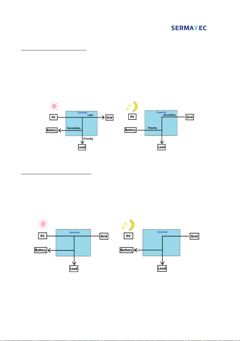
Mode 3: Micro-grid mode
Suitable for Areas without Grid
1. The Micro-grid power source comes from PV, battery.
2. If PV is sufficient, PV power priority supply to the load, then charge the battery. (Figure1-10)
3. When PV is insufficient, Batteries supply power to the load. (Figure1-11)
Typical application scenarios:
Figure1-9 Sunny day Figure1-10 Night
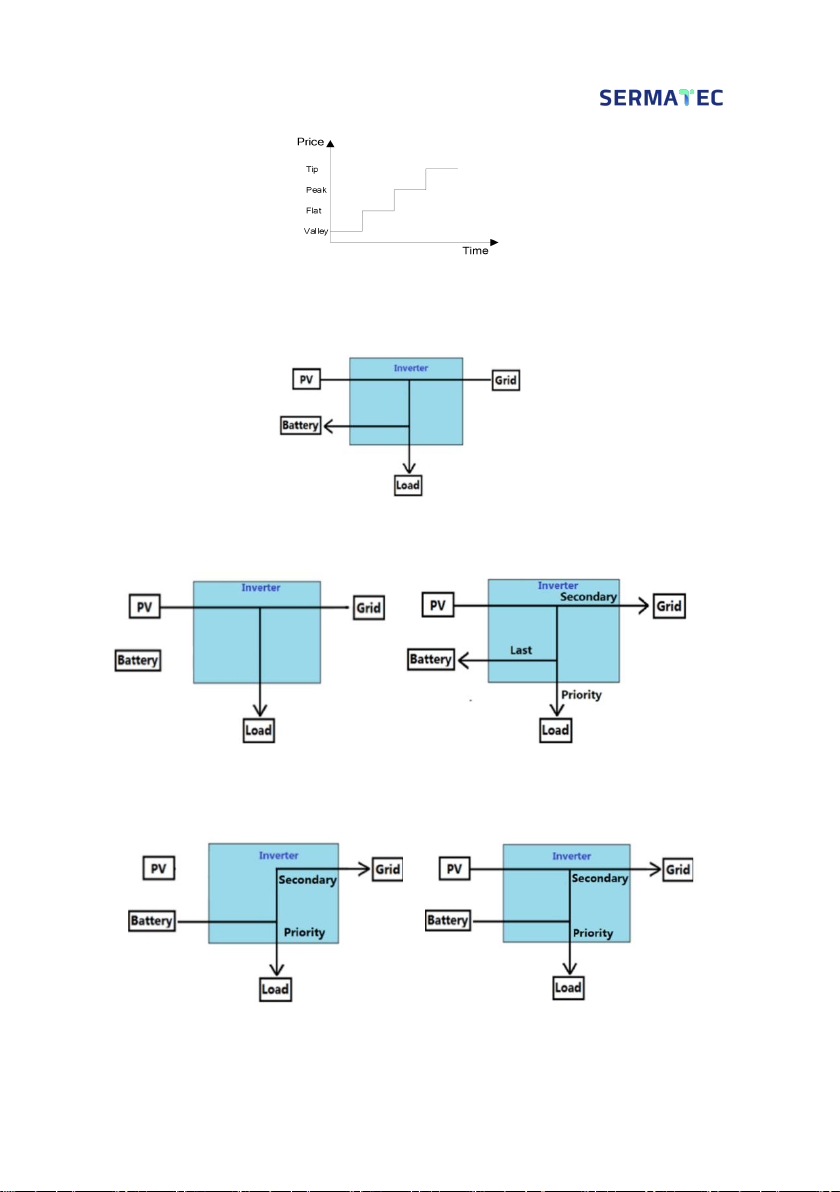
Mode 4: Peak-Bottom mode
Suitable for Areas with Changing Electricity Price
According to the electricity price of utility, the whole day can be divided into four periods (most of
the place): tip, peak, flat, and bottom price.
1. During the price of bottom period, the grid or/and PV charge the batteries and supply to loads
together to storage the electric power,battery never discharge at this stage.
2. During the price of flat period, when the PV is sufficient, it provides power in the sequence of
load,battery and grid.
3. During the price of tip and peak period, the battery and PV provides power to the laod, if more
energy will sell to Grid to obtain profit. Battery never charges at this stage.
Typical application scenarios:
5
Figure1-11 Grid price
In Bottom Time Period:
Figure1-12
In Flat Time Period:
Figure1-13 PV is insufficient Figure1-14 PV is sufficient.
In Tip and Peak Time Period:
Figure1-15 PV is insufficient Figure1-16 PV is sufficient

6
Mode 5: AC coupling mode
Suitable for the scenario that grid-tied inverter already there
Cooperate with the existing grid-tied inverter to build a storage system to get more profit. The joint
point is the Grid side or AC terminal.
1. Inverter communicates with CT (smart meter), CT is used to detect the on-gird power;
2. When PV surplus, battery with low SOC(less than 100%): Surplus PV will firstly provides to
loads(backup loads and AC grid loads),then charge the battery ,lastly sell to grid;
3. When PV surplus, battery with full SOC: PV supply power to the load firstly, and then the rest
power of PV will feed into the grid;
4. When PV insufficient: Battery and PV supply power to the load simultaneously; Battery and grid
supply power to the load simultaneously when battery with lower limit of SOC or discharge power
not enough;
5. Off-grid: Battery supply power to backup load;
6. APP will display: Battery charge/discharge power; Backup load power; AC grid load power, and
on-grid power.
Note: CT must be installed under AC-coupling working mode, CT self-checking default enabled,
the device will not start if the CT self-checking(meter detection) failed.
Meter/CT here only communicates with hybrid inverter, so if you enable anti-backflow it works for
hybrid inverter only, cannot work on grid-tied inverter as Sermatec inverter cannot control the grid-
tied inverter.

7
Figure 1-17 AC Coupling System Diagram

8
2 Installation
This chapter describes the installation and wiring of the Hybrid Inverter. Please strictly follow the
instructions in this chapter to install and wire connection.
2.1 Safety regulations
The Hybrid Inverter has high voltage and large current inside. To ensure personal safety, the
following regulations should be noted at all times.
The Hybrid Inverter can only be installed by personnel who have received training in the Hybrid
Inverter and have a good knowledge of the Hybrid Inverter. During the installation process, always
observe the safety precautions and local safety regulations before the catalog of this manual;
Do not operate or maintain the inside of the system during thunderstorms or wet weather to
prevent electric shock;
If operating inside the Hybrid Inverter, make sure the system is not powered on.
If the hybrid Inverter is equipped with an anti-theft lock, please be sure safekeepingof the key.
2.2 Installation preparation
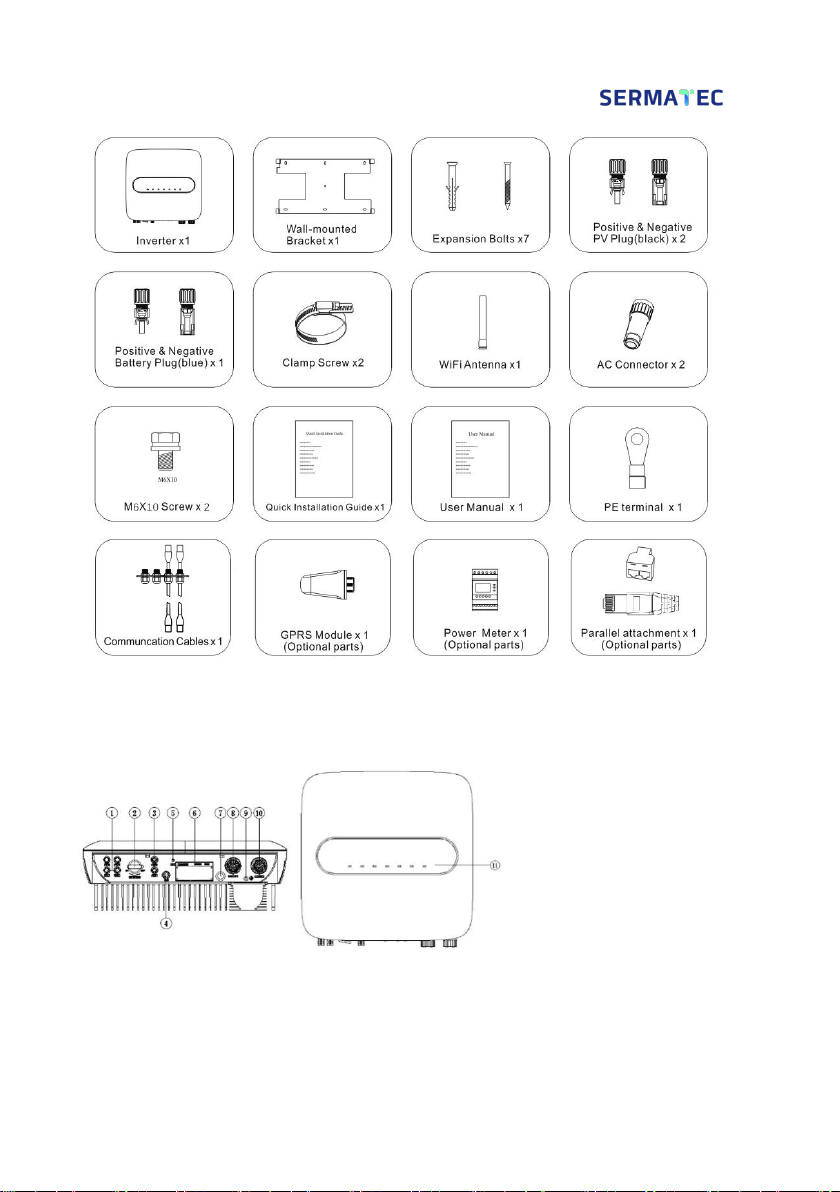
2.2.1 Unpacking inspection
Only when the goods arrive at the installation site can the unpacking box be allowed to be
inspected. The inspection is completed by the customer's representative and the supplier's
representative. Unpack the package, review the checklist.
9
Figure 2-1 Packing list
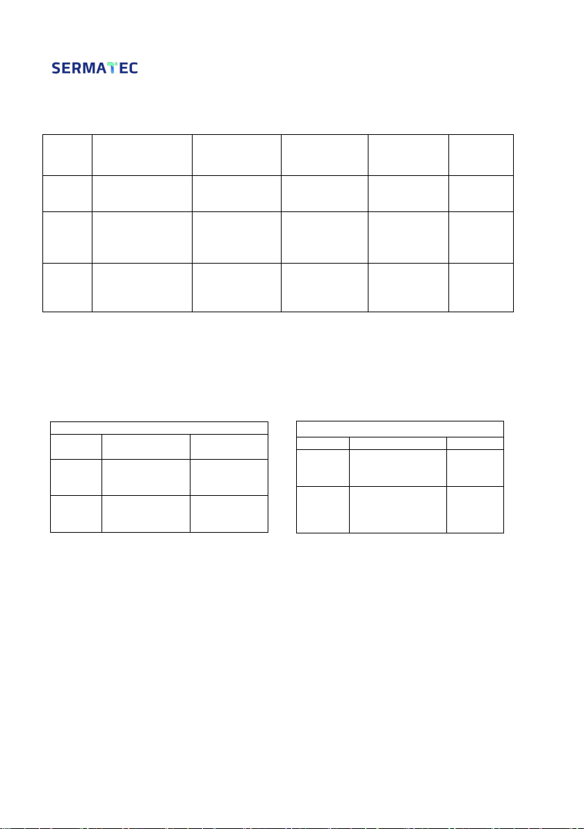
2.2.2 The Hybrid Inverter Overview
1. PV Connector
2. PV Switch
3. Battery connector
4. GPRS Module Interface
5. WIFI Antenna Interface
6. Communication Interface
7. Waterproof vent valve
8. AC Backup Load Connector
9. PE connection Point
10. AC Grid Connector
11. Indicator LED
Figure 2-2 The Hybrid Inverter Overview
10
2.2.3 Cable and Air switch preparation
Table 2-1 Wiring and cable requirements table
Serial
Cable Name
Recommended
model
cross-sectional
area(mm²)
Color of cable
Cable
OD(mm)
1
PV side DC positive
and negative input
PV1-F
4~6
Red, Black
ø4.5~
ø7.8
2
Battery side DC
positive and negative
input
PV1-F
6
Red, Black
ø4.5~
ø7.8
3
AC output
UL1015 10AWG
4~6
Yellow,
Green, Red,
Blue,
Yellow-Green
ø11~ø20
Note: Be sure all cables withstand voltage, temperature resistance, equal to or
better than the recommended model, and complying with relevant regulation of the
electrical industry.
Selection of switch
Table 2-2 Table 2-3
2.2.4 Installation Kit
1. Electric drill (drilling bit: ¢8mm)
2. Screwdriver (Philips screwdriver: M3, M6; Flathead screwdriver: M3)
3. Wire stripper (4,6mm²)
4. Wire crimper 1 (Model: H4TC0001; Manufacturer: Amphenol)
5. Wire crimper 2(OT terminal, 4~6 mm²)
6. Open-end wrench (Model: H4TW0001; manufacturer: Amphenol)
7. Multimeter
Recommended DC switch
PV(option)
Battery(optio
n)
Rated
voltage
≥1000V DC
≥800V DC
Rated
current
32A
32A
Recommended AC switch
AC backup Load
AC Grid
Rated
voltage
≥250V AC
≥250V
AC
Rated
current
32A
32A

11
2.2.5 Installation requirements
1. Wall bracket Installation
1) It is necessary to ensure that the installation position is flat and the thickness of the whole wall
exceeds 100mm;
2) Ensure the installation wall is vertical to the ground. If it is sloping, the tilt angle is only allowed
to be less than 15°
3) Ensure the installation wall is solid enough to meet the requirements of load-bearing for the
hybrid inverter.
4) The mounting position is supposed to avoid direct sunlight.
Figure 2-3 Perpendicularity requirement
2. Installation space requirements
Product installation position, leave 300 mm of space for maintenance and heat dissipation left,
right, and front
Figure 2-4 Mounting distance

12
2.3 Installation
2.3.1 Mounting
STEP 1: Mark mounting hole on the wall,drill hole with 8mm diameter of the bit. Ensure a depth
of 80mm.
Figure 2-5
STEP 2: Hammer expansion tube into the wall mount bracket on the wall, keep aligned with the
holes.
Figure 2-6
STEP 3: Mount the hybrid inverter on the bracket.
Figure 2-7

13
STEP 4: Secure the inverter with M6 screw on the right side.
Figure 2-8
STEP 5: Install anti-theft lock if necessary (Optional, equipped by user).
Figure 2-9
2.3.2 Electrical Connection
Hybrid Inverter System Connection Diagram
Figure 2-10

14
For AU/EN
Figure 2-11
For Other Countries
Figure 2-12
Other manuals for SMT-10K-TL-TH
1
Table of contents
Other Sermatec Inverter manuals


Popular Inverter manuals by other brands


MGE UPS Systems
MGE UPS Systems 3.5 to 21 kVA N+1 owner's manual

SMA
SMA Sunny String Monitor - Cabinet Installation and use

Schweizer
Schweizer Solrif Short installation manual

Wagan
Wagan 2406 user manual

Hitachi
Hitachi SJ2-CO instruction manual

Mitsubishi Electric
Mitsubishi Electric FR-A8AP instruction manual