TOYODenki VF66B User manual
■目 次
1.特長・機能…………………………………… 1
2.機種一覧……………………………………… 5
3.標準仕様………………………………………6
4.共通仕様 ……………………………………… 7
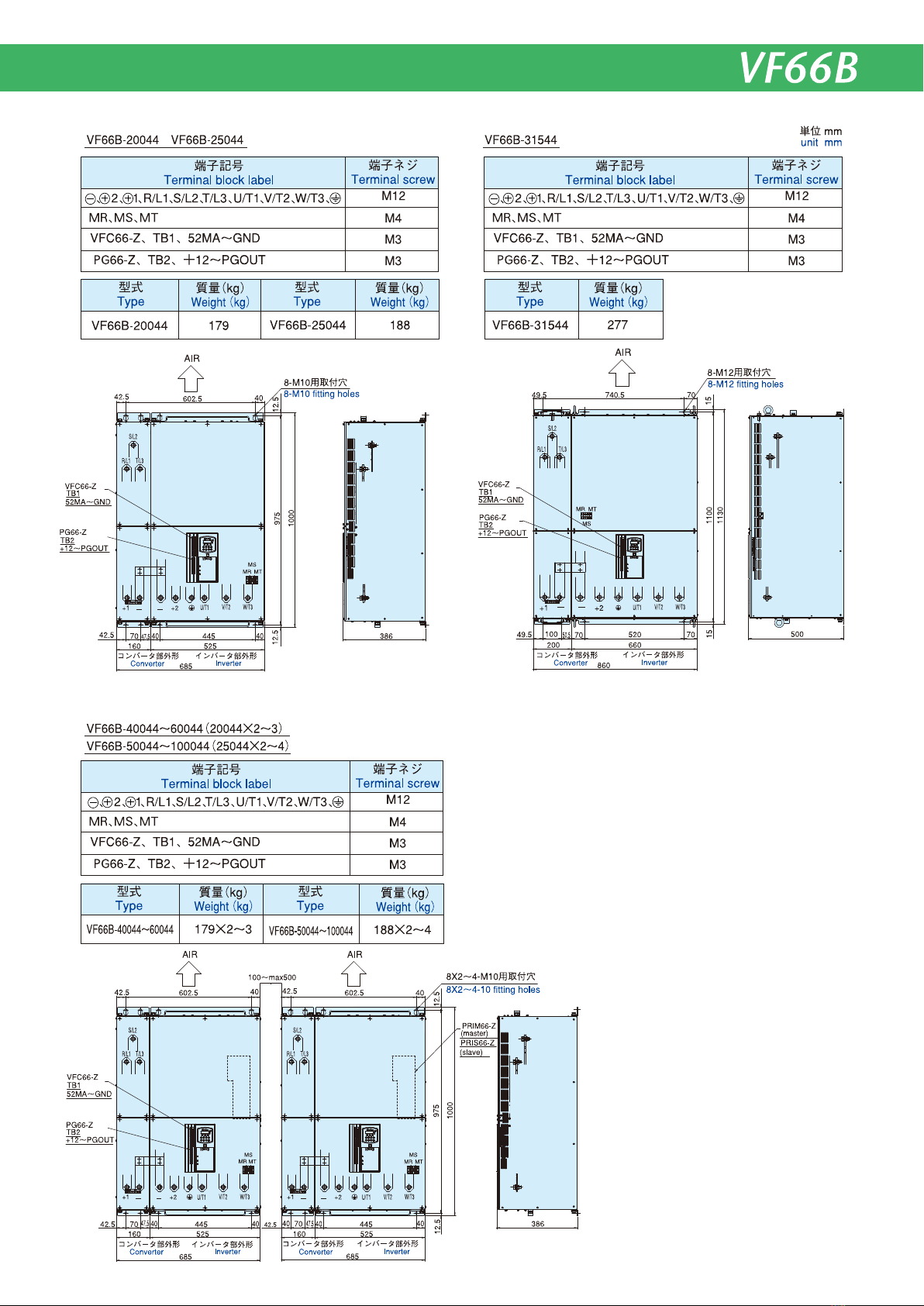
5.外形寸法 ……………………………………… 9
6.回路構成 …………………………………… 16
7.端子仕様 …………………………………… 17
8.標準機能…………………………………… 19
9.周辺機器オプション……………………… 26
10.海外規格への適合について……………… 44
11.機能アップオプション…………………… 50
12.注意事項…………………………………… 57
13.産業製品保証について…………………… 60
■INDEX
1.FeatureandFunction………………………1
2.ListofTypes……………………………… 5
3.StandardSpecifications………………… 6
4.CommonSpecifications………………… 7
5.OutlineDimension………………………… 9
6.CircuitComposition………………………16
7.TerminalSpecifications…………………17
8.StandardFunction………………………19
9.PeripheraldevicesandOptions……26
10.Conformitytoforeignstandards…… 44
11.Function-upOption……………………… 50
12.Caution……………………………………… 57
13.IndustrialProductWarranty………… 60
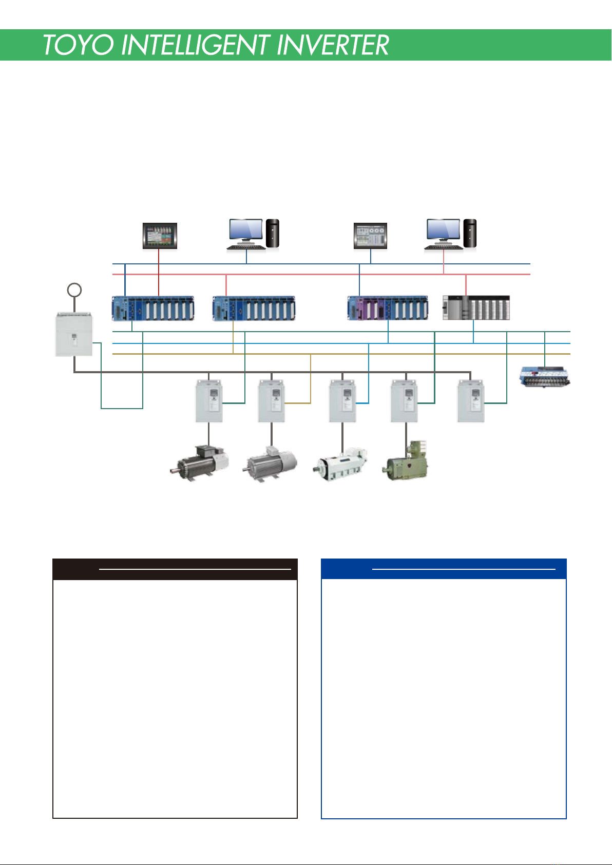
VF66Bインバータは、あなたのアイデアを100%実現します。
VF66BInvertercanrealizeyouridea100%.
〜
Ethernet
FL-net
(OPCN-2)
FAコントローラ
OPCN-1(JPCN-1)
RS-422
μGPCsH PLC 型DSP 装置 μGPCdsP 他社 PLC
PROFIBUS DP
DeviceNet
直流ステージ
VF66Bシリーズ
インバータ
永久磁石型同期モータ
EDモータ
インバータ用誘導モータ
UFモータ
電源回生コンバータ
(コモンコンバータ)
VF66R
電源
直流モータ
タッチパネル タッチパネル パソコン
MES(製造実行システム)
VF66B
VF66CH/CH66
直流電源装置
(バッテリシミュレータ)
VF66B
低慣性モータ
DSDシリーズ
VF66SV VF66B
(DCドライブモード)
リモート I/O 端子台
FA controller
PLC-type DSP controller μGPCdsP Third-party PLC
DC stage
VF66B series
inverter
ED motor
Permanent magnet
synchronous motor
UF motor
Induction motor
for inverter
VF66R
Regenerative converter
(common converter)
Power supply
DC motor
Touch panel Touch panel Computer
Manufacturing execution system (MES)
DC power supply
equipment
(battery simulator)
DSD series
Low-inertia motor
(DC drive mode)
Remote I/O Terminal
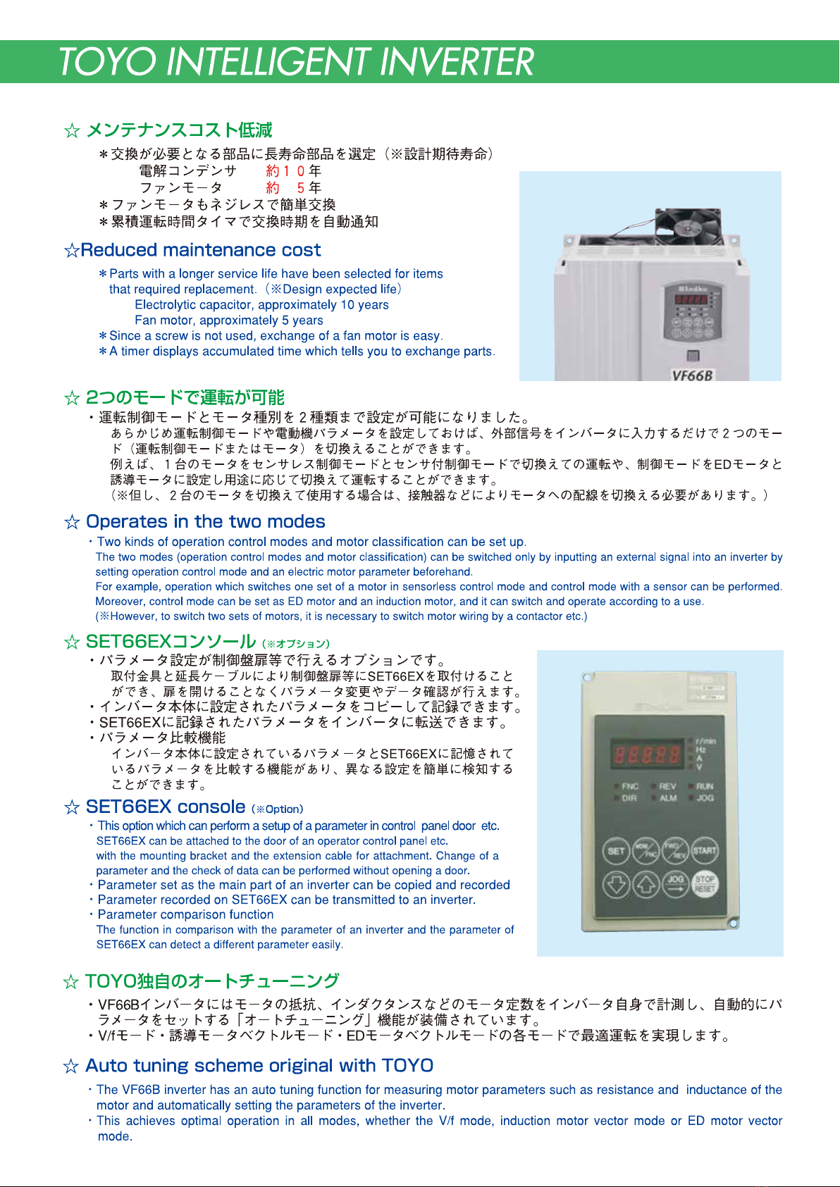
1.特長・機能 FeatureandFunction
☆多彩なアプリケーションに対応
☆ invertercanrespondtomanyapplications.
1台に5モードを搭載する多才なインバータ
VF66Binverterisaversatileinverterwhichcarriesfivefunctionsinoneset.
永年培ってきた東洋電機のモータドライブ技術を結集した「VF66Bインバータ」は、誘導モータおよびEDモータ
の駆動ができ、幅広いアプリケーションに対応可能
VF66BinverterhasconcentratedthemotordrivetechnologywhichTOYODENKIhascultivatedforyearscandriveaninduction
motorandEDmotor,thereforeVF66Binvertercanrespondtomanyapplications.
☆システムにあわせたインバータのカスタマイズ機能
※EDモータは小型・高効率で、誘導モータ以上に高速・高応答が可能なモータです。
※EDmotorisamotorofsmallsize,andhighefficiencyandcanperformthesamecontrolasaninductionmotor.
◎適用事例
・V/f制御: 汎用誘導モータを可変速に制御する用途に適しています。
‥‥‥ファン・ポンプ・コンプレッサ・コンベア・ミキサ、な ど
・センサレスベクトル制御:
高トルクが必要またはV/f制御より精度の良い速度制御が必要な用途に適しています。
‥‥‥ゴム/樹脂等の押出機・製紙機のライン制御、印刷機械、など
(長時間の低速運転、低速での回生運転の一部は適さない場合があります。)
・センサ付ベクトル制御: 高トルク・高精度な速度制御が必要な用途に適しています。
‥‥‥フィルム・金属の巻取機、印刷機械、クレーン、な ど
◎Applications
・V/fcontrol: Appliestotheusewhichcontrolsthespeedofinductionmotors.
‥‥‥Fan,pump,compressor,mixer,conveyor,etc.
・Speedsensorlessvectorcontrol
: AppliestoahightorquerunormoreaccuratespeedcontrolrunthanaV/fcontrol.
‥‥‥Printingmachine,papermachine,injectionmachineforrubberandplastics,etc.
(Inprolongedlow-speedoperationandregenerationoperationatalowspeed,itmaybeinapplicable.)
・
Vectorcontrolwithspeedsensor
:Appliestohightorqueandahighlyprecisespeedcontrolrun.
‥‥‥Thewindingmachineofafilmandmetal,printingmachine,craneetc.
*1:冷温時。75kW以上は、max150% *2:上記は弊社専用モータ使用時
*1:Coldstarting.75kWormoreismax150%. *2:
ShowsspecificationsincaseofusecombinedwithTOYOinvertermotor.
−
−200% 200% 150% 200%
1:150 1:1000 1:100 1:1000
制御モード
Controlmode
速度制御範囲
Speedcontrolrange
始動トルク
Startingtorque
(*1)
誘導モータ Inductionmotor EDモータEDmotor
V/f制御
V/fcontrol Speedsensorless
vectorcontrol
Vectorcontrolwith
speedsensor
位置・速度センサレス
ベクトル制御
PositionandSpeed
sensorlessvectorcontrol
位置・速度センサ付
ベクトル制御
Vectorcontrolwith
positionandspeedsensor
☆Thefunctionwhichcancustomizeaninverterinaccordancewithasystem
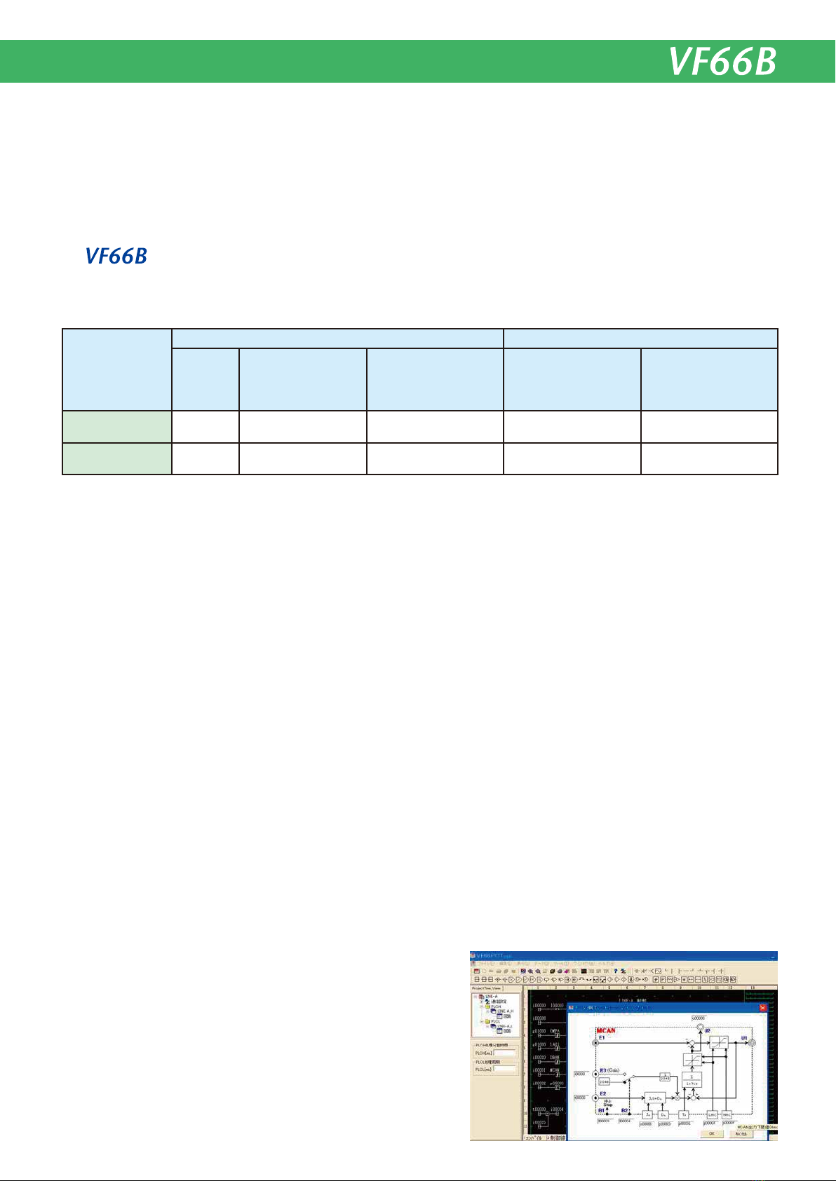
インバータ内蔵PLC機能により、インバータのモータ制御とシーケンス機能をカスタマイズし、お客様のシステムに
最適なインバータを提供します。(内蔵PLC機能の適用にはVF66PCToolが必要です。)
ByainternalPLCfunction,themotorcontrolandsequencerfunctionofaninverterarecustomizedandtheoptimalinverterfora
user'ssystemisoffered. (VF66PCToolisrequiredforausingofinternalPLCfunction.)
*内蔵PLC機能は、モータ制御に関する制御ブロックとシーケ
ンス機能をお客様がプログラミングしインバータに組込み、
各種用途に最適な制御を実現できる機能です。
(※VF66PCToolはオプションです)
*AinternalPLCisafunctionforausertoprogramtheoperation
blockwhichcontrolsamotor,andtheprocessingfacilityofan
input/outputsignals,toincludeinaninverter,andtorealizethe
optimalcontrolforvariousdestinations.
(※VF66PCToolisanoption.)
制御ブロックとシーケンス機能のプログラミング画面
Programmingwindowofcontrolblockandsequencerfunction
速度センサレス
ベクトル制御
速度センサ付
ベクトル制御
1

2
3
4
Showsincapacityofgeneralmotor.
*:Thereareusagerestrictions.Pleaseinformus.
Atthetimeofuseinvectorcontrolmode,whenpowersupplyvoltageisthesameasmotorratedvoltage,ifitbecomes90%
ormoreofratedspeed,controlprecisionetc.willfall.
Whenusinganinductionmotorbyvectorcontrolwithaspeedsensor,motorratedvoltageisusedwith90%orlessofsupplyvoltage.
(Note1)
(Note2)
(Note3)
(Note4)
一般的なモータ容量で示しています。
*:制限事項があります。詳しくはお問い合せください。
ベクトル制御モードでのご使用時、モータ定格電圧と電源電圧が等しい適用では定格回転速度の90%以上で制御精
度等が低下する場合があります。
誘導モータの速度センサ付ベクトル制御でご使用になる場合は、モータ定格電圧を電源電圧の90%以下としてご使
用ください。
(注1)
(注2)
(注3)
(注4)
Form
5
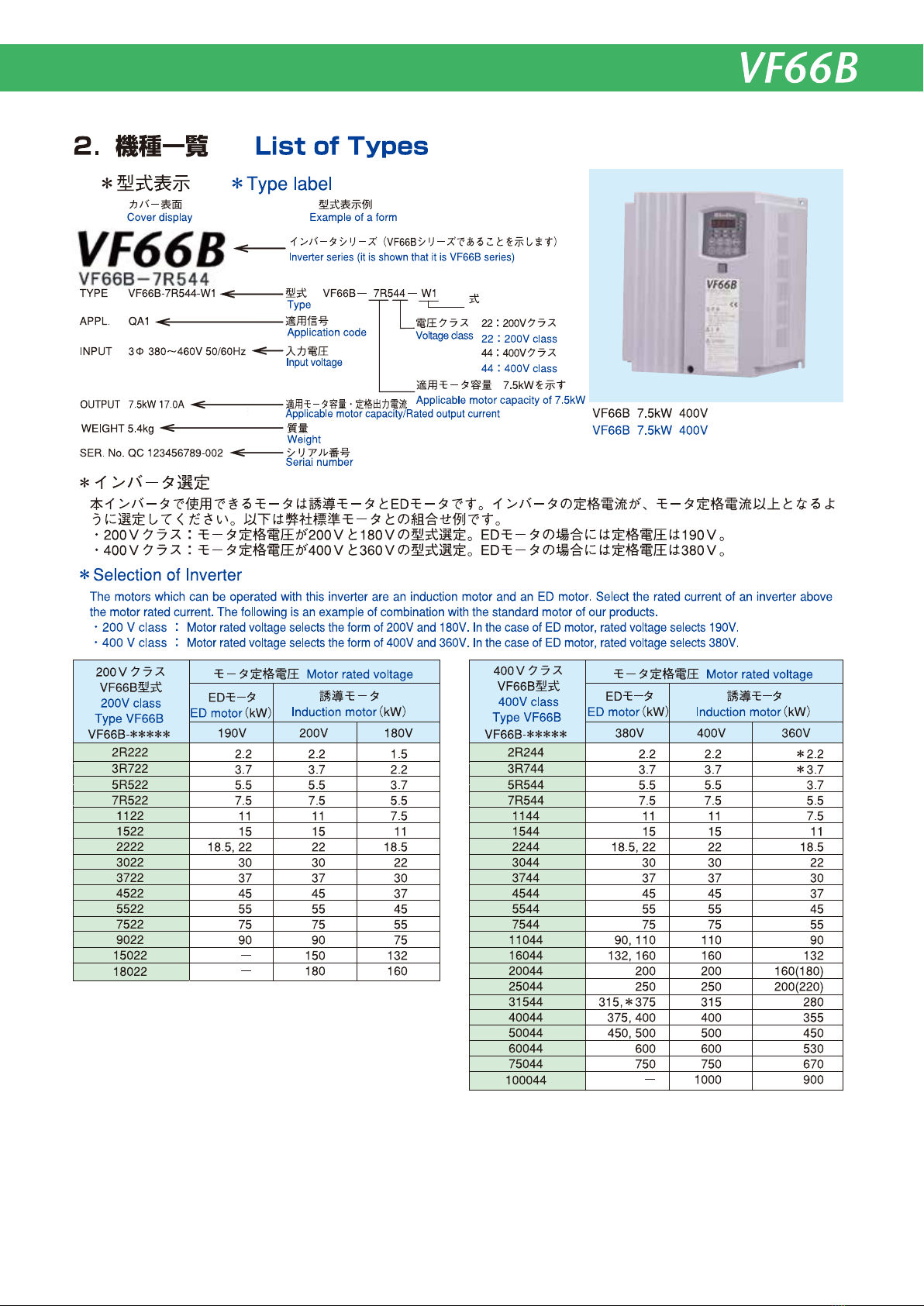
3.標準仕様 StandardSpecifications
●400Vクラス 400Vclass
●200Vクラス 200Vclass
(*1)一般的なモータ容量で示しています。
(*2)交流入力以上の電圧は出力できません。
(*3)定格出力時の値ですが、電源インピーダンスにより変わります。
(*4)( )内はオプションの直流リアクトル(DCL)を接続した場合の値を示します。
(*5)適用モータ定格出力時の値を示します。(電源インピーダンスにより変わります。)
(*6)直流リアクトルは2R2 22〜 55 2 2および2R24 4〜 5 54 4 の機 種ではオプションになります。
(*1)Showsincapacityofgeneralmotor.
(*2)VoltageofhigherthanACinputvoltagecannotbeoutputted.
(*3)Althoughitisanumericvalueatthetimeofratedoutput,itchangesbysourceimpedance.
(*4)ThevalueinbracketsisthevaluewhentheoptionalDCreactorisconnected.
(*5)Showsthevalueofratedoutputofappliedmotor.(Variesaccordingtopowersupplyimpedance.)
(*6)In5522and5544orless,DCreactorisanoption.
型式Type
VF66B
-
*****
適用モータ容量(kW)
定格出力電流(A)
最大出力電圧(V)
入力電圧(V)
入力力率
入力容量(kVA)
直 流 リ ア クト ル( オ プ シ ョ ン )
冷却方式
*1
*3
*5
Applicablemotorcapacity(kW)
Ratedoutputcurrent(A)
Max.outputvoltage(V)
Inputvoltage(V)
Inputpowerfactor
Inputcapacity(kVA)
DCreactor(DCL****)(Option)
Coolingsystem
2.2
2R222
10.0
200〜220V(入力電圧と対応)
200〜220V(complieswithinputvoltage)
三相三線200〜220V±10% 50/60Hz±5%
3phase3wire200〜220V±10% 50/60Hz±5%
遅れ約0.7(約0.9) Delayabout0.7(0.9)
4.95
DCL3R722
3.7
3R722
17.0
8.40
DCL3R722
5.5
5R522
24.0
12.1
DCL7R522
7.5
7R522
32.5
16.6
DCL7R522
強制風冷Forcedaircooling
*1
*3 *4
*2
*4 遅れ約0.9Delayabout0.9
*2
*5
*6
*6
2.2
2R244
5.5
380〜460V(入力電圧と対応)
380〜460V(complieswithinputvoltage)
三相三線380〜460V±10% 50/60Hz±5%
3phase3wire380〜460V±10% 50/60Hz±5%
遅れ約0.7(約0.9) Delayabout0.7(0.9)
4.95
DCL3R744
3.7
3R744
9.2
8.36
DCL3R744
5.5
5R544
13.0
11.9
DCL7R544
7.5
7R544
17.0
16.3
DCL7R544
11
1122
46.0
23.3
DCL1122
11
1144
24.0
23.2
DCL1544
15
1522
62.5
31.8
DCL1522
15
1544
32.5
31.7
DCL1544
22
2222 3022 3722 4522 5522 7522 9022 15022 18022
87.0
30
121
37
146
45
185
55
222
75
280
90
340
150
560
180
680
61.9
3.54 5.85 8.74 11.7 16.4 22.4
45.5
32.5 43.6
76.4
53.7
92.0
65.6
112
80.1
−
108
−
130
−
214
−
257
DCL2222 DCL3022 DCL3722 DCL4522 DCL5522 DCL7522 DCL9022 DCL9022
×2
DCL20044
×2 DCL25044
×2 DCL20044
×3 DCL25044
×3 DCL25044
×4
DCL7522
×2
22
2244
46.0
30
3044
62.5
37
3744
75.5
45
4544
92.5
55
5544
111
45.4
3.55 5.89 8.61 11.5 16.8 22.5 31.8
61.8 76.2 91.2 111
43.9 54.1 64.7 79.0
DCL2244 DCL3044 DCL3744 DCL4544 DCL5544
強制風冷Forcedaircooling
*4
*2
*4
*2
D C L なし
D C L あり
型式Type
VF66B
-
*****
適用モータ容量(kW)
定格出力電流(A)
最大出力電圧(V)
入力電圧(V)
入力力率
入力容量(kVA)
直 流 リ ア クト ル( オ プ シ ョ ン )
冷却方式
*1
*3
*5
Applicablemotorcapacity(kW)
Ratedoutputcurrent(A)
Max.outputvoltage(V)
Inputpowervoltage(V)
Inputpowerfactor
Inputcapacity(kVA)
DCreactor(DCL****)(Option)
Coolingsystem
*1
*3
*5
*6
*6
75
7544
146
380〜460V(入力電圧と対応)
380〜460V(complieswithinputvoltage)
三相三線380〜460V±10% 50/60Hz±5%
3phase3wire380〜460V±10% 50/60Hz±5%
遅れ約0.9 Delayabout0.9
−
107
DCL7544
110
11044
210
−
157
DCL11044
160
16044
300
−
225
DCL16044
200
20044
370
−
281
DCL20044
250
25044
460
−
348
DCL25044
315
31544
600
−
439
DCL31544
400
40044
740
−
557
500
50044
920
−
696
600
60044
1110
−
836
750
75044
1380
−
1046
1000
100044
1840
−
1394
強制風冷Forcedaircooling
*2
*2
型式Type
VF66B
-
*****
適用モータ容量(kW)
定格出力電流(A)
最大出力電圧(V)
入力電圧(V)
入力力率
入力容量(kVA)
直 流 リ ア クト ル( オ プ シ ョ ン )
冷却方式
*1
*3
*5
Applicablemotorcapacity(kW)
Ratedoutputcurrent(A)
Max.outputvoltage(V)
Inputpowervoltage(V)
Inputpowerfactor
Inputcapacity(kVA)
DCreactor(DCL****)(Option)
Coolingsystem
*1
*3
*5
*6
*6
DCLisnotattached
WithDCL
D C L なし
D C L あり
DCLisnotattached
WithDCL
D C L なし
D C L あり
DCLisnotattached
WithDCL
6
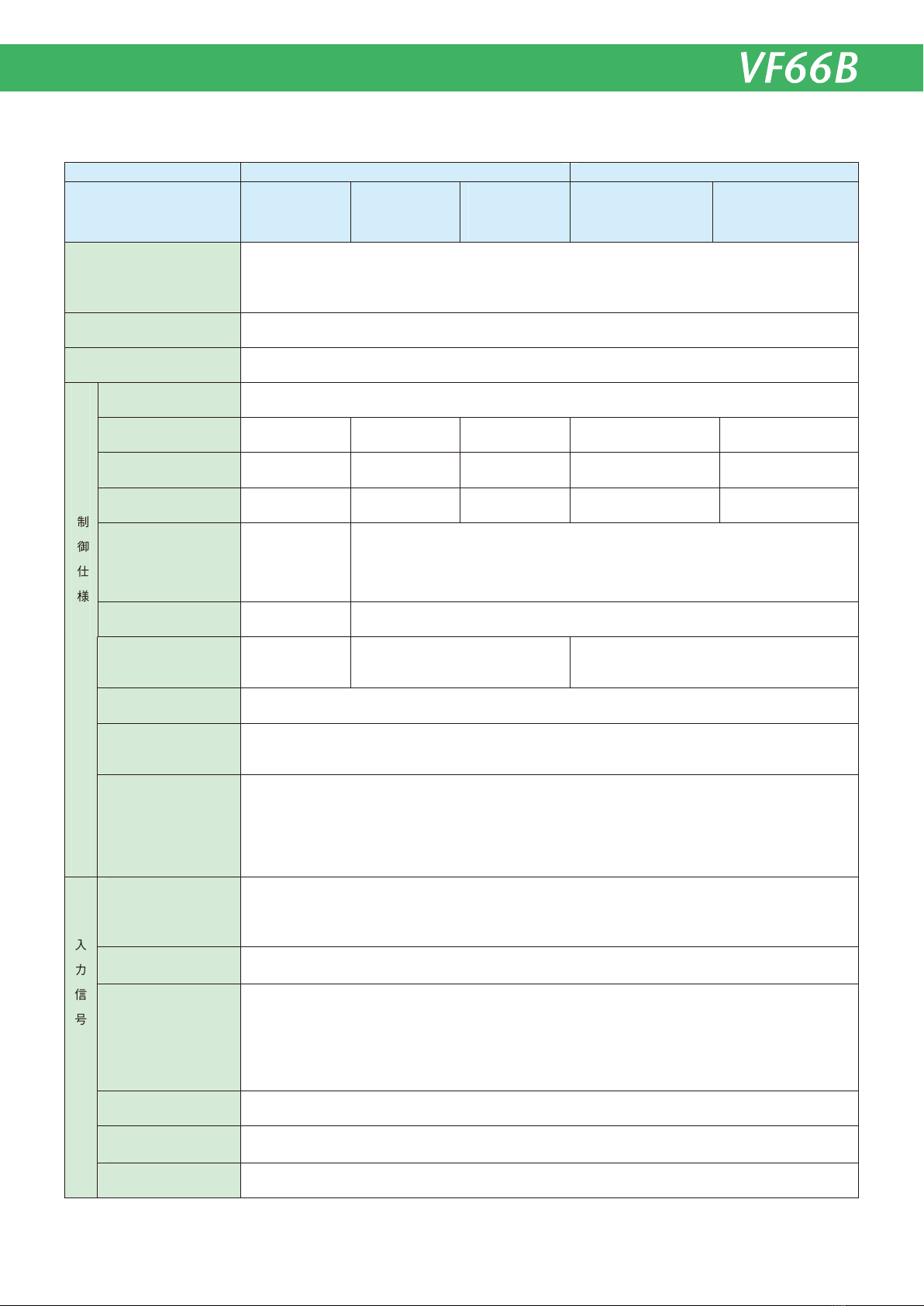
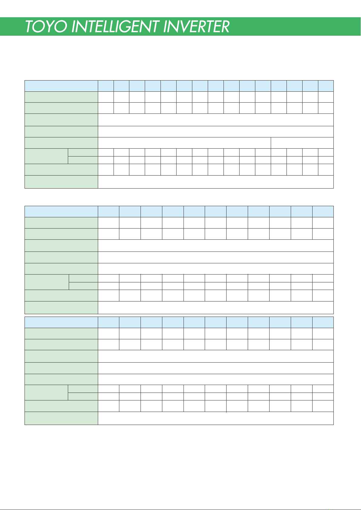
4.共通仕様 CommonSpecifications
固定機能端子
Fixedfunctionterminal
端子台入力
Terminalblockinput
トルク指令
Torquecommand
デジタル入力(オプション)
Digitalinput(option)
アナログ入力
Analoginput
その他運転機能
Otheroperational
functions
加減速時間
Accelerationand
decelerationtime
PWMキャリア周波数
PWMcarrierfrequency
定出力範囲(PC範囲)
Powerconstantoutputrange
(PCrange)
トルク制御
Torquecontrol
トルク制限
Torquelimit
速度制御精度*6
Speedcontrolaccuracy*6
速度制御範囲*6
Speedcontrolrange*6
最大始動トルク*3
Maximumstartingtorque*3
出力周波数範囲
Outputfrequencyrange
過負荷電流定格
Overloadcurrentrating
電源定格・変動
Powersourceratingandfluctuation
適用モータ容量*2
Applicablemotorcapacity*2
回転速度/周波数指令
Rotationalspeed/
frequencycommand
1接点:正転運転指令
1connect:Normaloperationcommand
シンクモード/ソースモード切換え可能
Sinkmode/Sourcemode
0〜±10V(150%/-10V) ±10000digit(150%/7500digit)*8
PROFIBUS、CC-Link、DeviceNet、OPCN-1、RS-485(ModbusRTU)、EtherNet/IP
0.1〜3600.0秒(0.1秒ピッチ)
0.1〜3600.0s (0.1spitch)
1〜6kHz
−−−−
−−−−
−−−−
−−−−
1:4 1:1.33
±0.5%
1:150
200%
±0.01%
1:1000
200%
±0.01%*7
1:100
150%
±0.01%
1:1000
200%
不可
Unavailable
可
available
力行・回生
Poweredoperation
andregenerative
範囲:0〜200%
Range:0〜200%
正転力行・正転回生・逆転力行・逆転回生範囲:各0〜200%
Normalpowered,normalregenerative,reversepowered,reverseregenerative
Range:0〜200%foreach
0.1〜400.0Hz
150%(60秒)、200%(3秒)*3150%(60s)、200%(3s)*3
200Vクラス:200〜220V±10%、50/60Hz±5%
200Vclass:200〜220V±10%、50/60Hz±5%
200Vclass:2.2kW〜180kW
400Vclass:2.2kW〜1000kW
200Vクラス:2.2kW〜180kW
400Vクラス:2.2kW〜1000kW
400Vクラス:380〜460V±10%、50/60Hz±5%
400Vclass:380〜460V±10%、50/60Hz±5%
0〜10Vまたは±10V (最高回転速度/10V、最高周波数/10V)
0〜10Vor±10V(maximaumrotationalspeed/10V,maximumfrequency/10V)
4〜20mA(最高回転速度/20mA、最高周波数/20mA)
4〜20mA(maximaumrotationalspeed/20mA,maximumfrequency/20mA)
±20000digit(最高回転速度/20000digit、最高周波数/20000digit)*8
±20000digit(maximaumrotationalspeed/20000digit,maximumfrequency/20000digit)*8
制 御 仕 様
ControlSpecificatons
入 力 信 号
Input
signal
寸動、S字加減速、速度/周波数ジャンプ、垂下制御、回生失速防止、瞬時停電再始動、DCブレーキ、初励
磁 *5、回転方向切換え、オートチューニング、保護リトライ、冷却ファンON/OFF機能、累積運転タイマ、
トルクブースト*4、スタビライザ*4、V/f特性(V/f一定、2乗低減、折れ線)*4
Inching, S-curve acceleration and deceleration, speed/frequency jump, droop control, regenerationstall
preventation,instantaneouspowerfailurerestarting,DCbrake,initialexcitation*5,rotationdirectionswitching,
autotuning,protectedretry,coolingfanon/offfunction,cumulativeoperationtimer,torqueboost*4,stabilizer
*4,V/fcharacteristics(V/fconstant,squarereduction,brokenline)*4
0〜10V/±10V/4〜20mA(標準1ch、オプション最大2ch、外部オプション2ch。※ただし標準1ch、オプ
ション1chは4〜20mA入力可)
0〜10V/±10V/4〜20mA(Astandardis1ch.Anoptionis2chatthetimeofamaxima.Anexternaloption
is2ch.Standard1chand1chofanoptionareenablesasa4〜20mAinputinthoseinputs.)
モータタイプMotortype 誘 導 モータInductionmotor EDモータEDmotor
制 御 モ ー ド
Controlmode
V/f制御
V/fcontrol
速度センサレス
ベクトル制御*1
Speedsensorless
vectorcontrol*1
速度センサ付
ベクトル制御
Vectorcontrolwith
speedsensor
位置・速度センサレス
ベクトル制御
Positionandspeed
sensorlessvectorcontrol
位置・速度センサ付
ベクトル制御
Vectorcontrolwithposition
andspeedsensor
7
*1:速度センサレスベクトル制御の場合は、回生時に十分なトルクが得られないことがあります。*2:一般的なモータ容量で示しています *3:冷温時。75kW以上は、max 150% *4:V/f
制御のみの機能 *5:誘導モータベクトル制御のみの機能 *6:弊社専用モータ適用時 *7:速度制御範囲を1:10に制限する場合 *8:通信オプション使用時 *9:内蔵PLCの編集をするに
はパソコンツールのControlBlockEditorが必要 *10:オプション
Notes:**1Invectorcontrolwithoutspeedsensor,sufficienttorquemaynotbeobtainedduringregeneration.*2Showsincapacityofgeneralmotor.*3Atcooltemperature.75kWormore
ismax150%.*4V/fcontrolonly*5Inductionmotorvectorcontrolonly*6UsingToyoDenkicustommotor*7Withspeedcontrolrangerestrictedto1:10*8Usingcommunication
option*9ControlBlockEditorofPersonalcomputertoolisrequiredforeditingtheinternalPLC. *10option
*10
*10
*10
*10
モータタイプMotortype 誘 導 モータInductionmotor EDモータEDmotor
制 御 モ ー ド
Controlmode
V/f制御
V/fcontrol
速度センサレス
ベクトル制御*1
Speedsensorless
vectorcontrol*1
速度センサ付
ベクトル制御
Vectorcontrolwith
speedsensor
位置・速度センサレス
ベクトル制御
PositionandSpeed
sensorlessvectorcontrol
位置・速度センサ付
ベクトル制御
Vectorcontrolwithposition
andspeedsensor
ユニット保護構造
Protectivestructureofunit
環境条件
Ambientenvironment
パソコンツール
PersonalcomputerTool
パソコン接続ケーブル
Personalcomputerconnectingcable
保護機能
Protectivefunction
コンソールモニタ表示
Consolemonitordisplay
関数(スーパブロック)
Function(superblock)
シーケンス
Sequence
プログラム容量
Programcapacity
PIアンプ、速度制御等約15種類
PIamplifier,speedcontroletc.(approximately15types)
16kB、約1024ステップ
16kB,approximately1024steps
機能端子
Functionterminal
2点(標準)
2output(standard)
2点(オプション)
2output(option)
アナログモニタ出力
Analogmonitoroutput
回転/周波数計用出力
outputforspeed
/frequency
機能端子
Functionterminal
5点(標準)
5input(standard)
6点(オプション)
6input(option)
IP00(JISC0920):開放型で人体に対する保護、固形物体の侵入に対する保護、水の浸入に対する保護を特に考慮していない構造
IP00(JISC0920):Theopentypestructurewhichisnotspeciallytakenintoconsiderationabouttheprotection
toahumanbody,theprotectiontoabreak-inofasolidobject,andtheprotectiontopermeationofwater.
動作温度:0〜50℃,湿度:20〜90%RH(結露のないこと),標高:1000m以下,保存温度:-20〜60℃,雰囲気:腐食
性ガス・金属粉・油・ハロゲン・DOP等の可塑剤が含まれないこと, 振動:5.9m/s2
(0.6G以下 10〜55Hz) JIS
C60068-2-6準拠 IEC60664-1に規定される過電圧カテゴリⅢ、汚染度2以下の環境下
Operatingtemperature:0〜50℃,Humidity::20〜90%RH(nocondensation),Altitude:1000morless,Storagetemperture:-20〜60
℃,Atmosphere:harmfulgas,metallicparticle,oil,andnoplasticizer(halogenorDOP).Vibration:5.9m/s2(0.6Gorless,10〜55Hz)
JISC60068-2-6compliant.EnvironmentsunderovervoltagecategoryⅢprescribedinIEC60664-1,pollutiondegree2orless.
ConsoleDataset(パラメータ設定)、ControlBlockEditor(内蔵PLC編集)、VFMonitor(運転・保護モニタ)
Console Dataset(parameter setting), Control Block Editor(Internal PLC editing). VF monitor (operation and
protectionmonitor)
出力周波数、回転速度、回転速度/周波数指令値、出力電流、出力トルク、直流電圧、入出力端子チェック、保護履歴、他
Outputfrequency,rotationalspeed,rotationalspeed/frequencycommandvalue,outputcurrent,outputtorque,
DCvoltage,input-outputterminalcheck,protectionhistory,other
回転速度/出力周波数の6倍のPWMパルス(アナログメータ接続可能・標準アナログ出力と同時使用は不可)
PWMpulseofrotationalspeedorPWMpulseofoutputfrequencyof6times(analogmetercanbeconnected・
Theconcurrentusewithstandardanalogoutputisimproper.)
プリセット回転速度/周波数指令(7点)、加減速時間選択(4種類)、接点による加速減速運転、回転速度
/周波数ホールド、S字加速・減速の禁止、最高回転速度/最高周波数低減、垂下制御不動作、トルク制御
選択、逆転運転指令、DCブレーキ指令、初励磁指令、外部故障信号(4接点)、トレースバック外部トリガ、
第2設定ブロック選択、非常停止B接点、回転速度/周波数指令端子台選択、逆転運転指令、正転寸動指令、
逆転寸動指令、非常停止、A接点保護リセット
Presetrotationalspeed/frequencycommands(7kinds),accelerationanddecelerationtimeselection(4types),
acceleration-decelerationoperationusingthecontact,rotationalspeed/frequencyhold,S-curve acceleration
and deceleration prohibited, maximum rotational speed/maximum frequency reduction, droop control
non-operation, torque control selection, reverse operation command, DC brake command, initial excitation
command, external failure signal(4 contacts), traceback external trigger, second setting block selection,
emergency stop (Normally closed), rotational speed/frequency command terminal block selection, reverse
operationcommand,forwardjoggingcommand,reversejoggingcommand,emergencystop,normallyopen
protectiveoperationreset
過電流、直流部過電圧、不足電圧、過速度/過周波数、過トルク、モータ過熱、フィン過熱、充電抵抗過熱、IGBT保護動
作、過負荷保護、記憶メモリ異常、電流センサ異常、始動渋滞、通信タイムアウトエラー、速度制御エラー、FCL動作、他
Overcurrent,DClinkovervoltage,lowvoltage,overspeed/overfrequency,overtorque,motoroverheating,finoverheating,
charging resistor overheating, output overload ( electronic thermal ), IGBT protected operation, memory error, current
sensorerror,startupstall,communicationtime-outerror,speedcontrolerror,fastcurrentlimitoperation,etc
入力:5点(標準) 12点(オプション) 、上位CPUから通信入力(オプション)
出力:オープンコレクタ 2点(標準)、4点(オプション)、接点出力(1a、1c)、上位CPUへの通信出力(オプション)
内部リレー種類:入力リレー、出力リレー、オンタイマ、オフタイマなど
命令:A接点、B接点、C接点、極性反転、加算、減算、乗算、除算、剰余、など約30種類
Input:5(standard),12(option),communicationinputfromhostCPU(option)
Output:opencollector2(standard),4(option),contactoutput(1normallyopen,1changeover),communicationoutputtohostCPU(option)
Internalrelaytypes:inputrelay,outputrelay,ontimerrelay,offtimerrelayetc.
Command:Normallyopen,Normallyclosed,Changeover,polarityinversion,addition,subtraction,multiplica-
tion,division,residueetc.(approximately30types)
オープンコレクタ出力Opencollectoroutput
出力項目: 回転速度/周波数検出(2点)、設定到達、トルク検出(極性付・絶対値の2点)、停電中、過負荷プリアラーム、
リトライ中、逆転中、保護動作コード、運転中、タイマ1経過、タイマ2経過、第2設定ブロック選択中、
ファンモータ故障中
Outputitems:rotationalspeed/frequencydetection(2kinds),settingattainment,torquedetection(polarityand
absolutevalue,2 kinds), outage, overloadpre-alarm,retrying, operating in reverse,protectedoperation code,
operating,Timer1progress,Timer2progress,secondsettingblockselected,underacoolingfan'sfailure
0〜±10V(標準1ch、オプション2ch※ただしオプション1chは4〜20mA出力可能)
出力項目:出力電圧、出力電流、出力トルク、回転速度/出力周波数、回転速度指令/周波数指令、内蔵PLC出力、他
0〜±10V
(Astandardis1ch.Anoptionis2chand1chofanoptionareenablesasa4〜20mAinputinthoseinputs.s)
Output items: output voltage, output current, output torque, rotational speed/output frequency, rotational
speedcommand/frequencycommand,internalPLCoutput,etc
入力信号
Inputsignal
出
力
信
号
Outputsignal
内
蔵
P
L
C*
9
InternalPLC
*
9
USBIF66
8

10 10130
150
7.5 250
265
7.5
7.5 285
300
7.5
6.5 272
285
6.5
7.5 285
300 7.5 7.5 245
260 7.5
195 6 6
10 10
200
220
205
25 25100
150 195
103 92 10 10200
220
112.6 92.4
205
2626 100
152
5.5 274
285
5.5
8.58.5 200
217
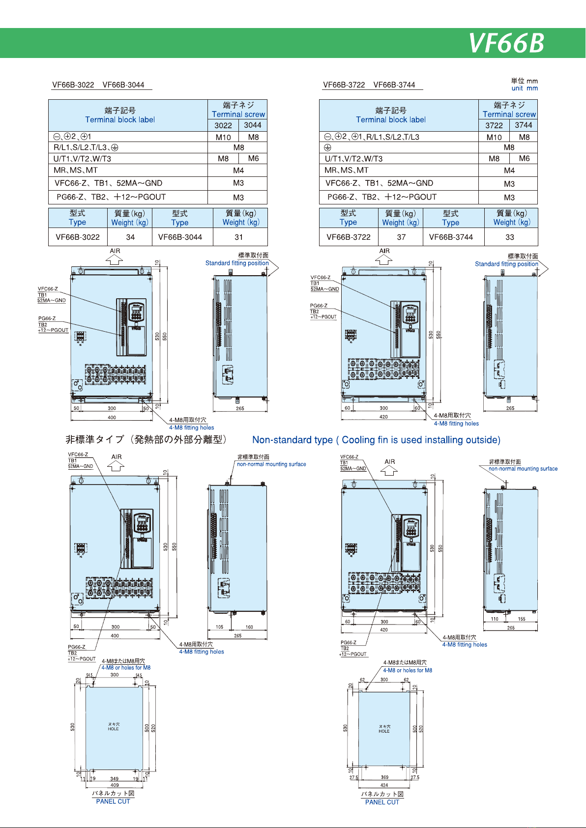
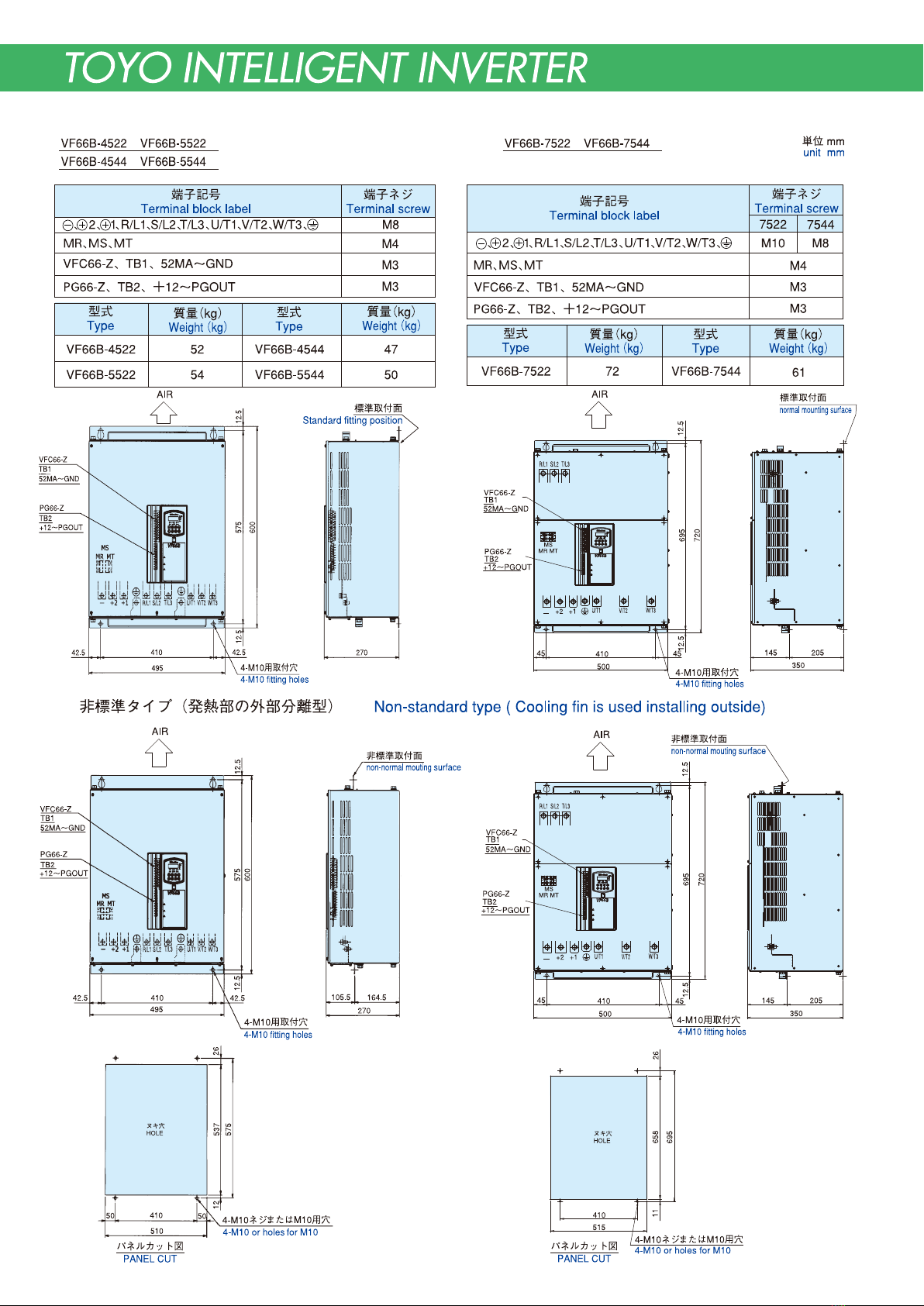
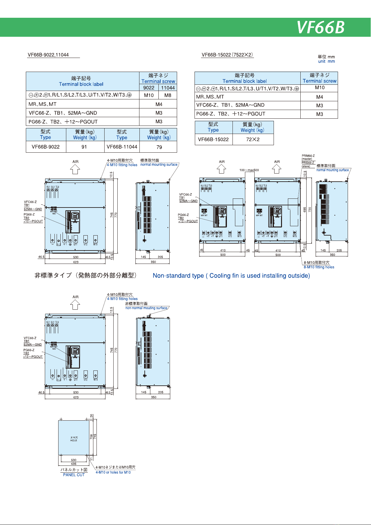
5.外形寸法 OutlineDimension
M5
M4
5.4
5.4
5.5
5.5
VF66B-5R522
VF66B-7R522
VF66B-5R544
VF66B-7R544
3.3
M3
M4
3.3
3.3
3.3
VF66B-2R222
VFC66-Z、TB1、52MA〜GND
、B、2、1、R/L1、S/L2、T/L3、U/T1、V/T2、W/T3、 、B、2、1、R/L1、S/L2、T/L3、U/T1、V/T2、W/T3
VFC66-Z、TB1、52MA〜GND
VF66B-3R722
VF66B-2R244
VF66B-3R744
M3
非標準タイプ(発熱部の外部分離型) Non-standardtype(Coolingfinisusedinstallingoutside)
端子ネジ
Terminalscrew
端子記号
Terminalblocklabel
型式
Type
質量(kg)
Weight(kg)
型式
Type
質量(kg)
Weight(kg)
端子ネジ
Terminalscrew
端子記号
Terminalblocklabel
型式
Type
質量(kg)
Weight(kg)
型式
Type
質量(kg)
Weight(kg)
VF66B-2R222VF66B-2R244
VF66B-3R722VF66B-3R744
VF66B-5R522VF66B-5R544
VF66B-7R522VF66B-7R544
Non-standard
fittingposition
(Optionmountingbracket)
4-M5fittingholes
4-M5fittingholes
orM5holes
Non-standardmountingholemanipulationfigure
Non-standardmountingholemanipulationfigure
4-M5用取付穴
4-M5fittingholes
4-M5用取付穴
4-M5fittingholes
4-M5用取付穴
4-M5fittingholes
4-M5用取付穴
非標準取付面
(オプション取り付け金具)
Non-standardfittingposition
(Optionmountingbracket)
非標準取付面
(オプション取り付け金具)
4-M5または
M5用穴
2-M5fittingholes
orM5holes
2-M5または
M5用穴
VFC66-Z
TB1
52MA〜GND
VFC66-Z
TB1
52MA〜GND
VFC66-Z
TB1
52MA〜GND
VFC66-Z
TB1
52MA〜GND
非標準取付穴加工図 非標準取付穴加工図
Standardfittingposition
標準取付面
Standardfittingposition
標準取付面
単位mm
unitmm
M3
PG66-Z、TB2、+12〜PGOUT
M3
AIR AIR
AIR AIR
PG66-Z
TB2
+12〜PGOUT
PG66-Z
TB2
+12〜PGOUT
PG66-Z
TB2
+12〜PGOUT
PG66-Z
TB2
+12〜PGOUT
ヌキ穴
HOLE ヌキ穴
HOLE
PG66-Z、TB2、+12〜PGOUT
9

10
11
12
13

14
15
※) 周辺機器の選定や設置については、12.注意事項を参照してください。
(注1) 制御入力端子(ST-F)および多機能入力端子(MI1〜MI5)は、GND共通入力(シンク入力)とすることも可能です。この場合、VFC66-Z
制御基板上のジャンパピンを[CNSO]から外し[CNSI]に取り付けます。(出荷時はPS共通入力(ソース入力)となっています。)
(注2) 制御回路のGND,COM端子は絶対にアースには接続しないでください。
(注3) 制動抵抗器(DBR)のサーマルリレーが動作した時はインバータ入力を遮断してください。
(注4) 主回路接触器(52M)はお客様のご使用に合わせて設置してください。
インバータの入力側に主回路接触器(52M)を設置する場合は、OFFしてから再投入するまで10分以上お待ちください。
(注5) 直流リアクトル(DCL)が接続されていない場合、 1端子と 2端子は短絡バーが付いています。
(注6) 11kW以上のユニットに付きます。
(注7) アース線は、IV電線でなく、KIV電線などの素線数の多い線を使用ください。
(注8) VFC66-ZとVFDB2009で通信を行う場合にDBIF2009-Zを使用します。詳しくは別冊「VFDB2009取扱説明書」をご覧ください。
(注9) 並列機種(<15022>〜<18022>、<40044>〜<100044>)の各ユニットにおいては、同一電源系統より給電してください。
※)Pleasereferto12.Cautionfortheselectionandthesettingaboutaperipheraldevice
(Note1)Controlinputterminals(ST-F)andmultifunctioninputterminals(M1〜M5)canalsobearrangedtoGNDcommoninput(sinkinput).
Inthiscase,removejumperpinonVFC66-ZP.C.Boardfrom[CNSO]to[CNSI].(StandardfactorydefaultsettingisPScommoninput(sourceinput).).
(Note2)NeverconnectGND,COMterminalofcontrolcircuitwithearth.
(Note3)Whenthermalrelayofdynamicresistor(DBR)tripped,breakinverterinput.
(Note4)Mountmaincircuitcontactor(52M)inaccordancewithuseconditionofcustomer.Pleasewaitfromturningofftothere-turningonfortenminutesormore
whenyousetonthemaincircuitcontactor(52M)ontheinputsideoftheinverter.
(Note5)IncaseofwithoutDCL,terminal 1and 2ofinverterareshorted.
(Note6)Unitof11kWormore.
(Note7)PleaseusenotIVcablebutcableswhichconsistofmoreconductorsuchasKIVcable.
(Note8)WhencommunicationisperformedbetweentheVFC66-ZandVFDB2009,theDBIF2009-Zisused.Formoreinfomation,seetheseparatevolume
"OperationManualforVFDB2009".
(Note9)Supplyelectricpowerfromthesamepowersupplyabouteachunitofaparallelmodels(<15022>through<18022>,<40044>through<100044>).
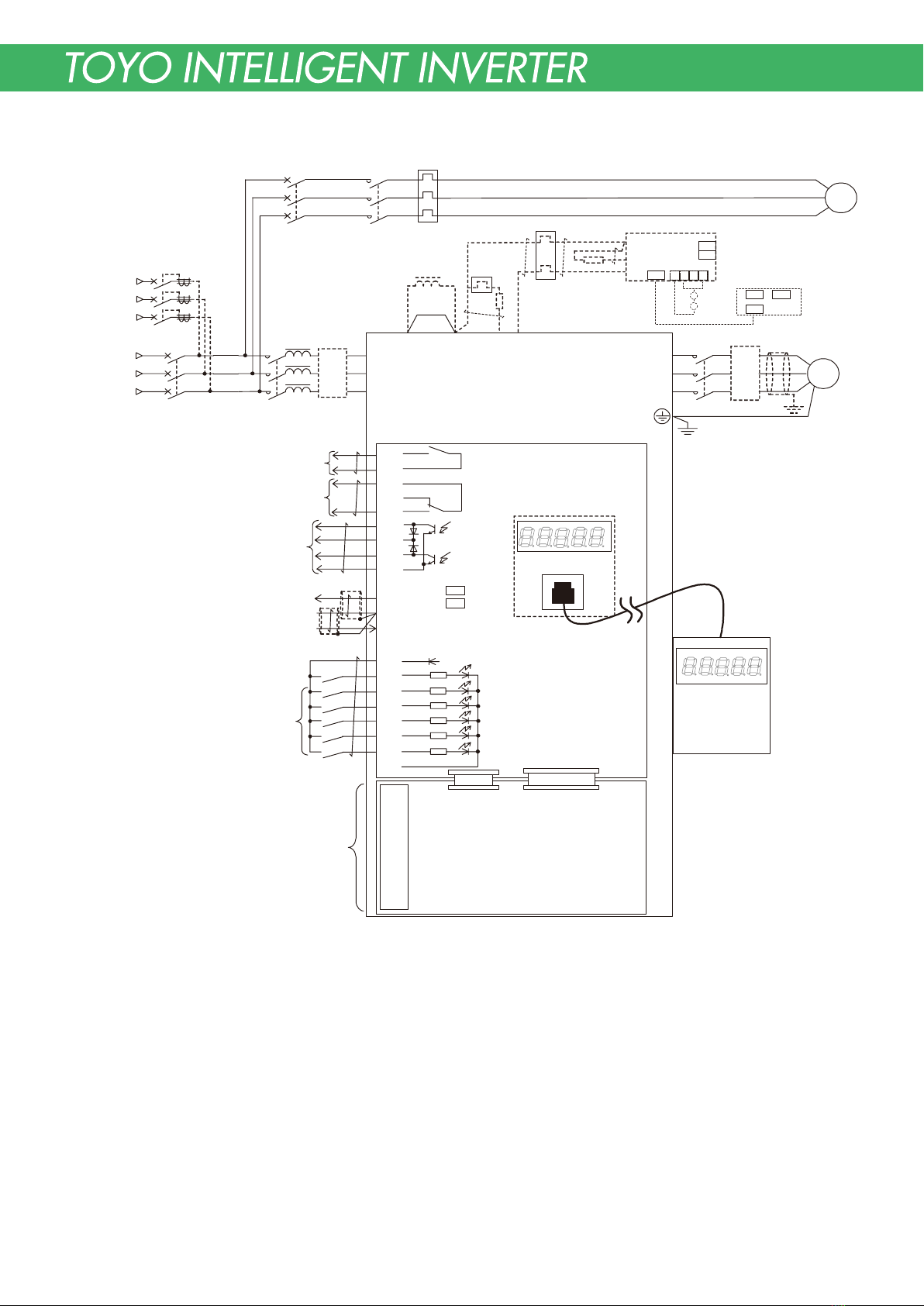
6.回路構成 CircuitComposition
配線用遮断器または漏電遮断器 ノイズフィルタ
オプション
Noisefilteroption
Circuitbreakeror
Earthleakagecircuitbreaker
多機能出力
(シーケンス
出力
)
多機能入力
(シーケンス入
力
)
多機能出力MO1〜MO2の機能は
SET66-ZあるいはSET66EXにより変
更可能です。詳しくは取扱説明書を
参照ください。(DC24V20mAMax)
インバータ運転
インバータ保護
Inverter
protec t ion
Inverterrun
Multifunctionaloutput(Sequenceoutput)
Thef unctionalityofthemultifunctionaloutput
MO1−MO2canbechangedbySET66-ZorSET66EX.
PleaserefertoOperationManualfordetails.
(Max.DC24V
/20mA)
Analoginputandoutput
ThefunctionalityofanaloginputAIN1and
analogoutputAOT1canbechangedby
SET66-ZorSET66EX.Pleasereferto
OperationManualfordetails.
(注1)
(Note1)
正転運転
(START-F)
アナログ入出力
アナログ入 力AIN1、アナログ出力
AOT1の機能はSET66-Zあ る い は
SET66EXにより変更可能です。詳しくは
取扱説明書を参照ください。
多機能入力MI1〜MI5の機能はSET66-Zあるいは
SET66EXにより変更可能です。詳しくは
取扱説明書を参照ください。
Multifunctionalinput(Sequenceinput)
Thefunctionalityofthemultifunctionalinput
MI1-MI5canbechangedbySET66-ZorSET66EX.
PleaserefertoOperationManualfordetails.
Analogoutput/
6Ffrequencyoutput
アナログ
出 力
/6F出力
アナログ
入力
A naloginput
(注3)
(注4)
(Note3)
(Note4)
52M
200〜220V
380〜460V
50/ 60Hz
R/L1
S/L2
T/L3
U/T1
V/T2
W/T3
P
PR
N
52MA
52MA
86A
86Ab
86Aa
M01
P
MO2
COM
AOT1
GND
AIN1
+10
PS
ST
-
F
MI1
MI2
MI3
MI4
MI5
GND
52MA
MCCB
-
F 88F 49F
86A
SET66
-
Z
(注2)
(注1)
(Note2) (Note1)
(注2)
(Note2)
CN
-
SI
CN
-
SO
インバータ運転接点
Inverterruncontact
インバータ保護接点
Inverterprotectioncontact
VFC66
-
Z
(注5)
(Note5)
(注3)
(Note3)
(注4)
(Note4)
(注8)(Note8)
(注3)
(Note3) 49B
52M
52MAX
DBIF2009-Z
EDM/IM
FM
49B
制動抵抗器
オプション
Brakeresistor
option
直流リアクトル
DBR
DBR
VFDB2009
CN2
CN3
CN6
CN1
CN2 CN3
400V
クラス
:CN2
200V
クラス
:CN3
400VclassCN2
200VclassCN3
1489
発電制動ユニットオプション
Dynamicbrakeunit(Option)
ノイズフィルタ
オプション
+1+2B −
(+12V)
CN7 CN4
PG66-Zまたは
オプション基板(IO66
-
Zなど)
+12
A
B
G
U/Z
V
W
PG
-
out
SET66EX
外部コンソールパネル
(オプション)
Externalconsolepanel
(Option)
PG66-ZorOptionP.C.Board
(IO66
-
Z,etc)
速度センサ入力
PGの配線については取扱説明書をご参照ください。
Speedsensorinput
標準ユニットにはPGインターフェイス基板が搭載
されています。PGインターフェイス基板には多機
能入出力は内蔵されていません。
PleaserefertoOperationManualforwiringofPG.
PGinterfaceP.C.boardisattachedtothestandardunit.
MultifunctionalinputandoutputarenotbuiltinPG
interfaceboard.
○ ○ ○
MR(注6)
(Note6)
MT
DCReactor
交流リアクトル
ACReactor
ア ー ス 線( 注 7 )
KIVCable(Note7)
Noisefilter
option
通信オプション基板
Communicationoptionboard
入力電圧
Inputvoltage
○
+○
+
○
+○
+
16

7.端子仕様 TerminalSpecifications
種類
Terminalblock
端子番号
Terminalnumber
用途
Application
内容説明
Explanationofcontent
交流入力
ACinput
交流電源に接続
ConnectwithACpowersource
3相モータに接続
Connectwith3-phasemotor
直流リアクトルを使用しない場合、1− 2短絡
Shortbetween 1- 2incaseofnouseDCreactor
発電制動用抵抗器・サーマルリレー接続用端子
電源回生コンバータ使用時には、直流電源の+側端子
Terminalforconnectionofdynamicbrakeresistorandthermalrelay.
+sideterminalofDCpowersourcewhenregenerativeconverterisused.
内蔵している発電制動用トランジスタのコレクタ端子
Terminalofcollectorterminalofbuilt-intransistorfordynamicbrake.
発電制動ユニット(DBユニット)のN端子との接続端子
電源回生コンバータ使用時には、直流電源の−側端子
TerminaltoconnectwithNterminalofdynamicbrakeunit(DB-UNIT).
-sideterminalandDCpowersourcewhenregenerativeconverterisused.
必ずアースに接続してください。
ノイズフィルタ(NF)使用時はNFのアース端子と接続します。
Surelyconnectwithearth.
Connectwithearthterminalofnoisefilter(NF)whennoisefilterisused.
インバータ運 転中 O N (接点容量:AC230V/0.5A最小DC5V/0.1A)
Turnson,whileaninverteroperates(Contactcapacity:AC230V/0.5AminDC5V/0.1A)
インバータ保護モード中にON (接点容量:AC230V/0.5A)
Turnson,duringaninverterprotection
(Contactcapacity:AC230V/0.5A)
インバータ出力
Inverteroutput
直流リアクトル 接続用
ForconnectionofDCreactorprimary
発電制動用抵抗器(サーマルリレー)接続用
Forconnectionofdynamicbrakeresistor
(thermalrelay)
DBユニット接続。または電源回生コンバータ
使用時−側入力用
Forconnectionofdynamicbrakeunitor
for-sideinputwhenregenerative
converterisused.
アース端子
Earthterminal
運転接点出力
Contactoutputduringrunningofinverter
保護接点出力
Contactoutputofprotectiveoperation
P端子
Pterminal
多機能出力端子1
Multifunctionoutputterminal1
多機能出力端子2
Multifunctionoutputterminal2
COM端子
COMterminal
アナログ出力端子1
Analogoutputterminal1
アナログ入力端子1
Analoginputterminal1
GND端子
Analoginput0voltterminal
R/L1・S/L2・T/L3
U/T1・V/T2・W/T3
B
52MA
86A
P
MO1
MO2
COM
AOT1
AIN1
GND
2
○
+
1
○
+
○
−
VFC66-Z
端子台
TB1
VFC66-Z
Terminal
blockTB1
主回路
Maincircuit
直流リアクトル 接続用および発電制動用
抵抗器(サーマルリレー)接続用。また
は電源回生コンバータ使用時+ 側入力用
For connection of DC reactor secondary and of
dynamic brake resistor (thermal relay) or of for
+sideinputwhenregenerativeconverterisused.
多機能出力端子には運転状況により信号が出力されます。
[初期状態では
・多機能出力端子1に周波数・速度指令に到達したら出力されるよう
に設定されています。
・多機能出力端子2に設定した周波数・速度を検出したら出力される
ように設定されています。
※オープンコレクタ出力(最大電圧 DC24V/最大出力電流 20mA)
・P端子は外部電源(DC)に接続してください。
Signalisoutputtedtomultifunctionaloutput-terminalbytherunstatus.
Atinitialstate,
・
Ifafrequencyandarotationalspeedreachafrequencyandarotational
speedcommand,itissetupsothatitmaybeoutputtedtothe
multifunctionaloutput-terminal1.
・Ifset-upthefrequencyandrotationalspeedaredetected,itisset
upsothatitmaybeoutputtedtothemultifunctionaloutput-terminal2.
※Opencollectoroutput(Max.voltageDC24V/Max.outputcurrent20mA)
・
Pterminalisconnectedwithexternalpowersource.
・アナログ出力(AOT1)は0〜±10V出力、6F(周波数)出力の切換えが
可能。(最大出力電流1mA)
[初期状態ではインバータの出力電流を 5V/インバータ定格電流を
出力するように設定されています。]
・アナログ入力(AIN1)は設定データ切換えにより入力範囲を0〜±10V、
0〜10Vに切換えることが可能。また、SW1をONに切換えること
により4〜20mA入力に切換えることが可能
[初期状態では0〜10V入力に設定されています。]
・GNDはアース端子に接続しないでください。
・
Thechangeof0-±10Vor6F(frequency)outputispossiblefor
analogoutput(AOT1).(Max.outputcurrent1mA)
[Theinitialstateissetasoutputoftheinverteroutputcurrent.5Vis
outputtedbytheinverterratedcurrent]
・Theanaloginput(AIN1)canswitchaninputrangeto0-±10V,
and0-10Vbysetups.Moreover,SW1canchangetoa4-20mA
inputbyON.
[Intheinitialstate,itissetas0-10Vinput.]
・GNDisnotconnetedtoaearthterminal.
多機能出力
Multifunctionoutput
アナログ入出力
Analoginutandoutput
○
+○
+○
+○
+
30kW以上のユニットには付きません。
M R・M S・M T
制御電源用端子
外部から電源を供給する時に使用します。11kW以上に付きます。MSは未使用。
Itisnotattachedtotheunitof30kWormore.
controlcircuitpowersourceinput
EquippedwithTypesofVF66B-1122,VF66B-1144ormore.MSisnotuse.
17

18
Other manuals for VF66B
3
Other TOYODenki Inverter manuals


