SET Lynx-CustomFit LYNX2-LC User manual

Copyright © 2011 Sumitomo Electric Industries, LTD.
Lynx
Lynx-
-CustomFit
CustomFit®
®Splice
Splice-
-On
On Connector
Connector Ver. 2
Ver. 2
-
-LYNX2
LYNX2-
-LC
LC for
for Optical
Optical Cord
Cord (2.4/3mm)
(2.4/3mm) with
with Duplex
Duplex LC
LC Clip
Clip-
-
Installation
Installation Manual
Manual
SMF : G.652, G.657
MMF : MM50(OM2), MM50(OM3), MM50(OM4), MM62.5(OM1)
The Lynx-CustomFit® Splice-On Connector is designed
and manufactured to assure personal safety. Improper
operation can result in bodily injury and serious damage
to this product. Please read and observe all warnings
instructions given in this operation manual.
Wear safety glasses to protect your eyes when
handling optical fiber.
Never look into the end of a microscope or
optical cable connected to an optical output
device that is operating. Laser radiation is
invisible, and direct exposure can severely injure
the human eye.
Alcohol is flammable, causes irritation and is
harmful if swallowed or inhaled. Keep alcohol
away from heat, sparks, skin, and avoid contact
with eyes.
In the case of the work at the high place, please
be careful not to drop an assembling tool.
!
!
!
1. Improper assembly will result in a loss of
performance. Please read instructions given in this
operation manual and the operation manual of the
fusion splicer.
2. Never touch the fiber of the stub. It has been
inspected in the factory.
3. The product is sensitive to dirt or dust. Do not take
out any parts from the package until it is to be
used.
4. The characteristic will be influenced by the fiber
cleaved surface condition. Please use a cleaver
which has a good cleaving characteristic.
5. Do not remove the dust cap until the connector
has been completely assembled in order not to
cause an high insertion loss due to them.
For your safety operation
!
Precautions
Composition Assembling Tools
Fusion Splicer
T-Q101-CA,
etc.
Fiber Cleaver
FC-6S-C, etc. Jacket remover
JR-M03, etc. Kevlar Cutter
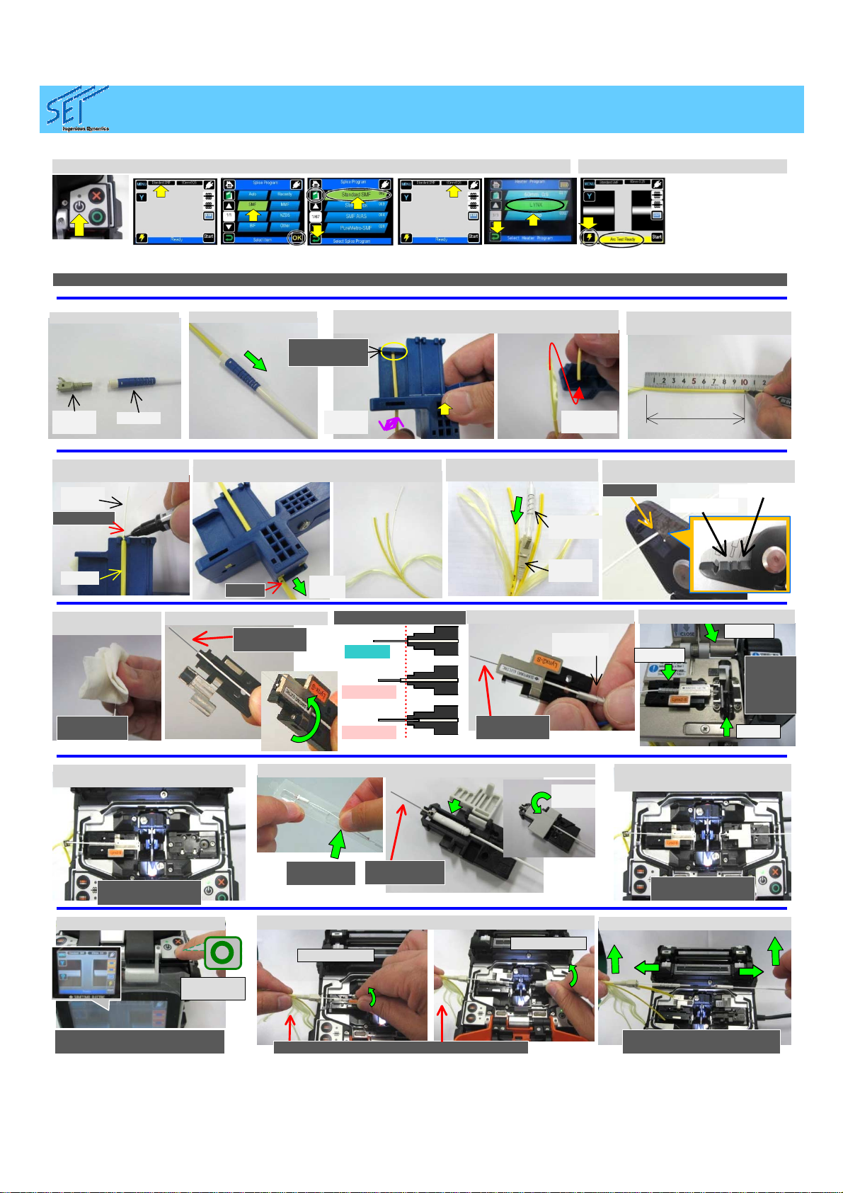
Recommended Program
Splicer Fiber Splicing Program Heater
Program
T-25eS SMF SM1: SMF1C Lynx
or FPS (60mm)
MMF MM1: MMF1C
T-39FH SMF LYNX-SM Lynx
or FPS (60mm)
MMF LYNX-MM
T-Q101-CA
(T-71C) SMF Standard SMF Lynx
or 60mm 0.9
MMF MMF 50&62.5
Please perform Arc test prior to the splicing
operation.
(See the operation manual of the splicer.)
*Fiber for testing is not included in the kit.
Please check fiber type inside the field fiber.
ETK1123160
E
Holder Type Cleave length:
10mm
Below equipments or tools are examples.
Disposable
Holder (*1)
Front
Housin
g
Rear
Stopper
Ferrule
Subassemb
ly
BootFurcation
Tube
Protection
Sleeve
and Spring
(*1) 1 pc / 100 connectors
Fiber Holder
LYNX2-UML-S Cord Tool
LYNX2-
CORDTOOL
Below tools are required.
North Carolina (USA)
Sumitomo Electric Lightwave Corp.
78 Alexander Drive, P.O. Box 13445, RTP, NC
27709
TEL +1-919-541-8100
http://www.sumitomoelectric.com/
Yokohama (Japan)
Sumitomo Electric Industries, Ltd.
(Lightwave Network Products Division)
1, Taya-cho, Sakae-ku, Yokohama 244-8588,
Japan
TEL +81-45- 853-7223, http://global-
sei.com/fttx/
London (UK)
Sumitomo Electric Europe Ltd.
220 Centennial Avenue, Elstree, Herts. WD6
3SL, UK
TEL +44 (0)20-8953-8118
http://www.sumielectric.com/
ver.E
Copyright © 2011 Sumitomo Electric Industries, LTD.
LYNX2
LYNX2-
-LC for Optical Cord
LC for Optical Cord (2.4/3mm) with
(2.4/3mm) with Duplex
Duplex LC
LC Clip
Clip
Assembly
Assembly Procedure
Procedure
(1) Disassemble Rear
Parts. (3) Open Cord Tool and set the cord on the proper
groove. Rotate the cord, then remove the outer
sheath.
Contact the
toptothewall
Rotate
the
cord
Remove
the
sheath
(13) Set fiber holder on the splicer
(left side).
Place fiber on
V-groove gently
(15) Set stub holder on the
splicer (right side).
Place fiber on
V-groove gently
(A) Set Fusion Condition
Push “power
key” for more
than 1 sec.
“Main Menu”
Select Fiber
Type Select “Fiber Type”, then “Return”.
(B) Perform Arc Test
Select “Arc Test”
Then perform the arc
test according to the
instruction.
*Fiber for testing is not
included in the kit.
Please check fiber type
inside the field fiber.
“Main Manu”
Select Sleeve
Type
Select Sleeve
Type
Then “Return”
See the operation manual of each splicer. These are the example of T-Q101-CA (T-71C).
ETK1123160E
3. Slide
Clean
rubber
clamp
and
blade
regularly
2. Close
1. Place
(12) Cleave the fiber (FC-6S)
(2) Slide Boot on Cord. (4) Mark at 100mm from the
end of Sheath.
100 mm
Mark Here
(5) Mark on 900um fiber
on Cord Tool.
Cord
900um
Fiber
Mark
(6) Set Cord on Tool with100mm Mark at the
edge of Cord Tool and pull. Then Outer
Sheath is separated.
Pull
the
cord
(7) Slide Rear Stopper and
Protection Sleeve onto the
fiber.
Rear
Stopper Boot
Rear
Stopper
Protection
Sleeve
(8) Remove the fiber coating from
the marking point. (JR-M03)
0.9 to
0.25mm
0.25 to
0.125mm
Mark
point
(9) Clean the fiber
with lint-free
cleaning wipe.
Moistened
with alcohol
(11) Set the sleeve on the
holder. Protection
Sleeve
Do not
touch bare
fiber
If the position of the fiber is
wrong, set the fiber or stub
again.
(16) Fusion Splice.
Button to
start
splicing
Lightly holding assembly to prevent bending
(17) Open the stub and fiber holders.
Left side first Then right
side
Lightly maintaining tension
to prevent bending
(18) Pick up the spliced fiber.
Confirm the position
Good
No Good
No Good
(10) Set the fiber on the
holder. Do not
touch bare
fiber
Grasp here
to pick up Do not touch
bare fiber
(14) Pick up the stub and set the stub on the plastic holder.
Push to
close
Copyright © 2011 Sumitomo Electric Industries, LTD.
LYNX2
LYNX2-
-LC for Optical Cord
LC for Optical Cord (2.4/3mm) with
(2.4/3mm) with Duplex
Duplex LC
LC Clip
Clip
Assembly
Assembly Procedure
Procedure
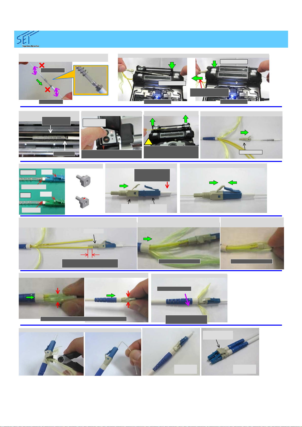
Complete
(Simplex)
(33) Trim Excess Kevlar by Kevlar Cutter and cut the tether.
(21) Confirm the position
before heating.
Sleeve at
center of
heater
No gap
Button to
start
heating
(22) Heat Protection Sleeve.
Lynx heater program runs a
fan to cool the sleeve after
heating
(23) Pick up Sleeve.
Be careful for hot sleeve,
spring and flange even
after the cooling by fan.
!
(32) Secure Kevlar by Kevlar Stopper.
No twisting
(19) Slide Protection until it covers the
projection of the flange.
No twisting No twisting
Lightly maintaining
tension on fiber
Right side
first
No twisting
Keep Fiber Straight
Rotate
clockwise.
(31) Slide Kevlar Stopper to the end, then Outer Sheath is held.
ETK1123160E
(30) Pull Kevlar and Hold Kevlar
with Housing.
Keep Fiber Straight
Hold Kevlar Tightly
Keep Fiber Straight, Hold Kevlar Tightly
(26) Slide Rear Parts.
Make sure
protrusion of cap
from Front
Housing.
(27) Put Rear Stopper in Front Housing.
Front
Housing
Rear
Stopper
(20) Set Sleeve into the heater. Then left side
(24) Slide Rear Stopper.
Rear
Stopper
(28) Adjust Outer Sheath Length so that it doesn’t overlap on
the thread of Rear Stopper. Thread
(29) Slide Boot slowly so that Fiber and
Kevlar are accommodated in slit outer
sheath.
Keep Fiber Straight
The edge of outer sheath
shall be located within the
range
Flat surface
Lever
Red dot
Lever
PC/UPC
APC
Flange Design
4 directions
available
1 direction only
(25) Key Alignment and push ferrule to the
end.
Complete
(Duplex)
Duplex Clip
(Option)
Table of contents
Other SET Cables And Connectors manuals


